ADCA-PRV 25 SS
ADCA-PRV 25 SS
ADCA-PRV 25 SS

Create successful ePaper yourself
Turn your PDF publications into a flip-book with our unique Google optimized e-Paper software.
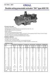
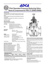
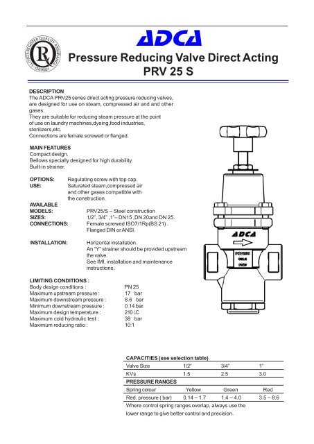
Pressure Reducing Valve Direct Acting<br />
<strong>PRV</strong> <strong>25</strong> S<br />
DESCRIPTION<br />
The <strong>ADCA</strong> <strong>PRV</strong><strong>25</strong> series direct acting pressure reducing valves,<br />
are designed for use on steam, compressed air and and other<br />
gases.<br />
They are suitable for reducing steam pressure at the point<br />
of use on laundry machines,dyeing,food industries,<br />
sterilizers,etc.<br />
Connections are female screwed or flanged.<br />
MAIN FEATURES<br />
Compact design.<br />
Bellows specially designed for high durability.<br />
Built-in strainer.<br />
OPTIONS:<br />
USE:<br />
Regulating screw with top cap.<br />
Saturated steam,compressed air<br />
and other gases compatible with<br />
the construction.<br />
AVAILABLE<br />
MODELS:<br />
<strong>PRV</strong><strong>25</strong>/S – Steel construction<br />
SIZES: 1/2”, 3/4” ,1”– DN15 ,DN 20and DN <strong>25</strong>.<br />
CONNECTIONS: Female screwed ISO7/1Rp(BS 21) .<br />
Flanged DIN or ANSI.<br />
INSTALLATION:<br />
Horizontal installation.<br />
An “Y” strainer should be provided upstream<br />
the valve.<br />
See IMI, installation and maintenance<br />
instructions.<br />
LIMITING CONDITIONS :<br />
Body design conditions : PN <strong>25</strong><br />
Maximum upstream pressure : 17 bar<br />
Maximum downstream pressure : 8.6 bar<br />
Minimum downstream pressure : 0.14 bar<br />
Maximum design temperature : 210 LC<br />
Maximum cold hydraulic test : 38 bar<br />
Maximum reducing ratio : 10:1<br />
CAPACITIES (see selection table)<br />
Valve Size 1/2” 3/4” 1”<br />
KVs 1.5 2.5 3.0<br />
PRE<strong>SS</strong>URE RANGES<br />
Spring colour Yellow Green Red<br />
Red. pressure ( bar) 0.14 – 1.7 1.4 – 4.0 3.5 – 8.6<br />
Where control spring ranges overlap, always use the<br />
lower range to give better control and precision.
CAPACITY TABLE<br />
Pressure Steam Compressed Air<br />
bar Kg/h Nm3/h -0 o C-1,013bar<br />
Inlet Outlet 1/2” 3/4” 1” 1/2” 3/4” 1”<br />
0,2 6 7 10 8 9 14<br />
2 1 26 32 42 35 39 58<br />
1,5 30 37 52 40 48 71<br />
0,3 12 15 21 15 18 27<br />
1 30 37 54 33 49 74<br />
3 1,5 42 52 73 54 67 101<br />
2 50 64 89 67 82 123<br />
2,5 66 70 99 75 93 138<br />
0,4 19 24 32 <strong>25</strong> 30 43<br />
1 38 45 69 49 61 89<br />
4 1,5 50 62 87 67 82 121<br />
2 62 77 108 82 100 150<br />
2,5 70 87 122 91 114 172<br />
3 75 92 129 98 121 189<br />
0,5 42 52 79 57 69 98<br />
1,5 60 75 105 79 100 144<br />
5 2 68 85 120 90 113 168<br />
3 88 108 153 115 143 213<br />
4 96 120 168 1<strong>25</strong> 155 232<br />
0,6 46 57 82 60 74 108<br />
2 74 92 132 98 123 181<br />
6 3 98 120 171 126 159 236<br />
4 110 136 192 142 180 265<br />
5 106 132 188 139 175 260<br />
0,7 50 63 89 67 84 119<br />
2 81 102 142 106 133 194<br />
7 3 104 131 182 135 171 <strong>25</strong>4<br />
4 118 148 206 154 194 288<br />
6 114 142 201 150 188 278<br />
0,8 54 67 94 71 88 129<br />
2 87 108 152 113 141 213<br />
8 3 112 138 196 146 181 272<br />
4 129 162 227 169 221 314<br />
6 138 173 245 180 <strong>25</strong>3 338<br />
0,9 48 63 92 67 82 1<strong>25</strong><br />
2 90 120 157 116 147 216<br />
9 3 116 145 204 151 189 280<br />
4 136 170 239 177 221 333<br />
5 150 187 264 195 244 363<br />
6 152 190 270 198 <strong>25</strong>2 378<br />
7 155 194 275 199 <strong>25</strong>0 374<br />
1 58 73 105 77 95 142<br />
2 92 121 164 122 151 227<br />
10 3 120 150 214 158 196 293<br />
4 142 178 <strong>25</strong>0 186 233 347<br />
6 170 212 297 208 277 412<br />
8 178 220 307 229 286 426<br />
1,1 66 82 121 88 108 160<br />
2 96 123 171 127 159 240<br />
3 130 162 227 170 212 316<br />
11 4 158 195 276 205 <strong>25</strong>5 380<br />
6 196 242 339 221 317 473<br />
8 214 266 374 278 347 518<br />
8,6 218 271 383 284 355 530<br />
1,2 73 95 132 99 126 186<br />
2 108 128 178 135 167 249<br />
3 138 170 240 177 221 332<br />
12 4 165 205 290 214 268 398<br />
6 206 <strong>25</strong>5 360 268 332 492<br />
8 230 285 404 300 374 578<br />
8,6 233 289 414 305 380 579<br />
1,3 85 106 148 111 140 208<br />
2 110 134 187 141 175 260<br />
3 141 175 249 185 231 343<br />
13 4 170 213 298 224 278 412<br />
6 217 281 382 283 350 527<br />
8 246 307 435 3<strong>25</strong> 403 604<br />
8,6 <strong>25</strong>1 314 445 356 412 615<br />
1,5 92 113 161 117 148 220<br />
2 112 138 196 142 179 266<br />
3 144 177 <strong>25</strong>2 187 236 348<br />
15 4 172 208 308 229 285 420<br />
6 202 290 390 284 365 544<br />
8 222 318 448 336 419 626<br />
8,6 240 355 459 343 428 639<br />
1,7 104 123 173 128 160 239<br />
2 116 141 196 145 183 270<br />
3 147 181 <strong>25</strong>8 191 241 355<br />
17 4 174 221 314 233 328 429<br />
6 206 296 404 300 373 556<br />
8 229 340 469 349 434 650<br />
8,6 <strong>25</strong>2 344 478 359 444 673<br />
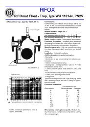
MATERIALS ( <strong>PRV</strong><strong>25</strong>/<strong>SS</strong> )<br />
POS. DESIGNATION MATERIAL<br />
1 BODY C 22.8<br />
2 COVER GGG40<br />
3* SEAT AISI 316<br />
4* GASKET COPPER<br />
5 * VALVE ST.ST. AISI 440<br />
6 * VALVE RETURN SPRING ST.ST. AISI 302<br />
7 * STRAINER SCREEN ST.ST. AISI 304<br />
8 PUSHROD ST.ST. AISI 316<br />
9 CAP A 105<br />
10 * CAP GASKET ST.ST. / GRAPHITE<br />
11* COVER BOLTS STEEL 8.8<br />
12 GUIDE BUSH GRAPHITE / PTFE<br />
13 STOP RING AISI 304<br />
14 * BELLOWS ST.ST. AISI 316TI<br />
15 * BELOWS GASKET ST.ST. / GRAPHITE<br />
16 * ADJUSTMENT SPRING STEEL<br />
17 TOP SPRING PLATE BRA<strong>SS</strong><br />
18 ADJUSTMENT SCREW ST.ST. AISI 304<br />
19 LOCKNUT ST.ST. AISI 304<br />
20 HANDWHEEL PLASTIC<br />
21 SPRING IDENT. PLATE ALUMINIUM<br />
*Available spare parts.<br />
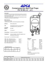
DIMENSIONS(mm<br />
SCREWED ENDS<br />
DIN FLANGES<br />
DN A B C F Kg D E Kg<br />
1/2” 90 65 175 74 3.2 150 47.5 4.6<br />
3/4” 90 65 175 74 3.2 150 52.5 5.2<br />
1” 100 65 175 74 3.7 160 57.5 6
abcde<br />
STEAM SPECIALITIES<br />
INSTALLATION AND MAINTENANCE INSTRUCTIONS<br />
PRE<strong>SS</strong>URE REDUCING VALVES<br />
( <strong>PRV</strong><strong>25</strong>S - <strong>PRV</strong><strong>25</strong><strong>SS</strong> - PRW<strong>25</strong><strong>SS</strong> )<br />
GENERAL<br />
1.These instructions must be carefully read before any work involving products supplied by VALSTEAM <strong>ADCA</strong><br />
ENGINEERING S.A. is undertaken.<br />
2.The installation procedure is a critical stage in a life of a valve and care should be taken to avoid damage to the valve or<br />
equipment.Reducing valves are designed to give accurate control of down-stream pressures.They give their maximum performance<br />
only when the equipment associated with them is correctly sized and installed in accordance with our recommendations.<br />
Warning !<br />
-If malfunction of any other equipment or system opperation failure may result in a dangerous overpressure ,overtemperature<br />
or even vacuum condition, a safety device must be included in the system to prevent such situations .<br />
-At start up , the presence of small particles in the fluid (dirt,scale,weld splatters,etc) may cause an unperfect closure of the<br />
seat . If this occur, proceed to an accurate cleaning.<br />
-Do not touch the equipment without appropriate protection during working operation because it may conduct heat if the<br />
used fluid is at high temperature.<br />
-Before starting maintenance be sure that the equipment is not pressurized or hot .<br />
-The equipments must be used within the working temperature and pressure limits laid down for them,<br />
otherwise they may fail ( refer to nameplate and/or IS- Information Sheet).<br />
-Do not remove the nameplate attacched to the equipment.Serial number and other useful information is stamped on it.<br />
INSTALLATION<br />
1.Prior to install check that the product is suitable for the intended application : materials and pressure/temperature ratings.<br />
2.Before to install remove plastic covers placed on flanges or connection ends. The equipment has<br />
an arrow or Inlet/Outlet designations.Be sure that it will be installed on the appropriate direction.<br />
3.Take care with jointing material to ensure that none may be permitted to block or enter the valve.<br />
4.Reducing valves are recommended to be fitted with the centre line of the valve in a vertical position to ensure that the best<br />
results are obtained.<br />
5.An <strong>ADCA</strong> pipeline strainer should be installed upstream of the valve to protect from dirt which could damage the valve or<br />
cause mal-functioning.<br />
6.The reducing valve pipework should be properly supported and free from strain and it should not be subjected to undue<br />
surges of pressure.<br />
For steam installations we strong recommend that the reducing valve is positioned where condensation is unable to collect<br />
or that, alternatively, separators and steam traps are are fitted so that the pipework drains correctly.The start up condition<br />
should be considered.<br />
MAINTENANCE<br />
1.We recommend that the pressure reducing valves are serviced as necessary.Pressure reducing valves should be checked<br />
periodically (at least yearly), to verify that they are operating correctly and to clean the internal parts and screen (if any).<br />
2.When reassembling make sure that all gasket faces are clean and always use a new gasket. Tighten<br />
cover bolts uniformly in a diagonal sequence.<br />
3.Valves in store for long periods should have their adjusting spring relaxed.<br />
4.For further information refer to the relevant <strong>PRV</strong> brochure or consult our Sales Office.<br />
LIMITING CONDITIONS <strong>PRV</strong> <strong>25</strong>:<br />
Body design conditions : PN <strong>25</strong><br />
Maximum upstream pressure : 17 bar<br />
Maximum downstream pressure : 8,6 bar<br />
Minimum downstream pressure : 0,14 bar<br />
Maximum design temperature : 210ºC<br />
Maximum cold hydraulic test : 38 bar<br />
LIMITING CONDITIONS PRW <strong>25</strong>:<br />
Body design conditions : PN <strong>25</strong><br />
Maximum upstream pressure : 14 bar<br />
Maximum downstream pressure : 8,6 bar<br />
Minimum downstream pressure : 0,35 bar<br />
Maximum design temperature : 75ºC<br />
Maximum cold hydraulic test : 38 bar<br />
Maximum reducing ratio : 10:1<br />
Maximum reducing ratio : 10:1<br />
CE Marking :<br />
This product have been designed for use on steam,air and other gases wich are in Group 2 of the PED-European Pressure<br />
Equipment Directive 97/23/EC and it comply with those requirements.<br />
The product fall within category SEP and must not be CE marked.<br />
LO<strong>SS</strong> OF GUARANTEE : Total or partial disregard of above instructions involves loss of any right to guarantee.<br />
VALSTEAM <strong>ADCA</strong> ENGINEERING SA - Trav.da Douroana -2419-006 Regueira de Pontes-Leria-Portugal<br />
IMI PR<strong>25</strong>.32 E 08.03
STEAM SPECIALITIES<br />
PARTS LIST FOR <strong>PRV</strong><strong>25</strong>S PRE<strong>SS</strong>URE REDUCING VALVES:<br />
Code Designation Valve size Pos.Nr. Qty.<br />
VR.9210.015 Bellows& body gasket DN1/2”-1” 14,15 1set<br />
VR.9210.115 Spring&body gasket (0,14-1,7bar) DN1/2”-1” 15,16,21 1set<br />
VR.9210.215 Spring&body gasket (1,4 - 4bar ) DN1/2”-1” 15,16,21 1set<br />
VR.9210.315 Spring&body gasket (3,5 - 8,6bar) DN1/2”-1” 15,16,21 1set<br />
VR.9213.015 Seat & plug package DN1/2” 3,4,5,6,7,10 1set<br />
VR.9213.020 Seat & plug package DN3/4” 3,4,5,6,7,10 1set<br />
VR.9213.0<strong>25</strong> Seat & plug package DN1” 3,4,5,6,7,10 1set<br />
Recommended tightening torques for <strong>PRV</strong><strong>25</strong>S :<br />
Pos.Nr. Size Nm<br />
3 1/2”-1” 100-110<br />
9 1/2”-1” 65-75<br />
11 1/2”-1” 20-<strong>25</strong><br />
Remarks: Tighten cover bolts uniformly.<br />
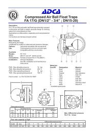
<strong>PRV</strong><strong>25</strong>S<br />
PARTS LIST FOR <strong>PRV</strong><strong>25</strong><strong>SS</strong> PRE<strong>SS</strong>URE REDUCING VALVES:<br />
Code Designation Valve size Pos.Nr. Qty.<br />
VR.9232.015 Bellows& body gasket DN1/2”-1” 14,15 1set<br />
VR.9232.215 Spring&body gasket (0,14-1,7bar) DN1/2”-1” 15,16,21 1set<br />
VR.9232.315 Spring&body gasket (1,4 - 4bar ) DN1/2”-1” 15,16,21 1set<br />
VR.9232.415 Spring&body gasket (3,5 - 8,6bar) DN1/2”-1” 15,16,21 1set<br />
VR.9233.015 Plug package DN1/2” 5,6,7,10 1set<br />
VR.9233.020 Plug package DN3/4” 5,6,7,10 1set<br />
VR.9233.0<strong>25</strong> Plug package DN1” 5,6,7,10 1set<br />
Recommended tightening torques for <strong>PRV</strong><strong>25</strong><strong>SS</strong> :<br />
Pos.Nr. Size Nm<br />
2 1/2”-1” 90-100<br />
9 1/2”-1” 65-75<br />
<strong>PRV</strong><strong>25</strong><strong>SS</strong><br />
PARTS LIST FOR PRW<strong>25</strong><strong>SS</strong> PRE<strong>SS</strong>URE REDUCING VALVES:<br />
Code Designation Valve size Pos.Nr. Qty.<br />
VR.9232.015 Bellows& body gasket DN1/2”-1” 14,15 1set<br />
VR.9232.115 Spring&body gasket (0,35-1,7bar) DN1/2”-1” 15,16,21 1set<br />
VR.9232.315 Spring&body gasket (1,4 - 4bar ) DN1/2”-1” 15,16,21 1set<br />
VR.9232.415 Spring&body gasket (3,5 - 8,6bar) DN1/2”-1” 15,16,21 1set<br />
VR.9234.015 Plug package DN1/2” 5,6,7,10 1set<br />
VR.9234.020 Plug package DN3/4” 5,6,7,10 1set<br />
VR.9234.0<strong>25</strong> Plug package DN1” 5,6,7,10 1set<br />
Recommended tightening torques for PRW<strong>25</strong><strong>SS</strong> :<br />
Pos.Nr. Size Nm<br />
2 1/2”-1” 90-100<br />
9 1/2”-1” 65-75 PRW<strong>25</strong><strong>SS</strong>
abcde<br />
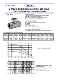
STEAM EQUIPMENT<br />
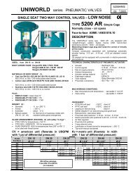
PRE<strong>SS</strong>URE REDUCING VALVE <strong>PRV</strong><strong>25</strong><br />
Typical Reducing Valve Installation<br />
MATERIALS ( <strong>PRV</strong> <strong>25</strong> )<br />
POS. DESIGNATION MODEL<br />
GGG40<br />
1 PRE<strong>SS</strong>URE REDUCING VALVE <strong>PRV</strong> <strong>25</strong><br />
2 HUMIDITY SEPARATOR S<strong>25</strong> or S16<br />
3 STEAM TRAP FLT SERIES<br />
4 SIGH GLA<strong>SS</strong> SW 12<br />
5 STRAINER IS 16<br />
6 STRAINER IS 16<br />
7 STOP VALVE GLOBE TYPE<br />
8 CHECK VALVE GLOBE TYPE<br />
9 STOP VALVE GLOBE OR GATE TYPE<br />
9A* BY-PA<strong>SS</strong> VALVE GLOBE TYPE<br />
9B STOP VALVE GLOBE OR GATE TYPE<br />
10 SAFETY VALVE ----<br />
11 COIL ----<br />
12 GAUGE COCK ----<br />
13 UPSTREAM PRE<strong>SS</strong>URE GAUGE ----<br />
14 DOWNSTREAM PRE<strong>SS</strong>URE GAUGE ----<br />
Remarks :<br />
* By-pass is optional .In case the by-pass is not allowed than stop valve 9B should be placed after pressure<br />
gauge 14 allowing the isolation of safety valve.<br />
PN classes and materials according to the operating pressures.<br />
Installation instructions are available (IMI - <strong>PRV</strong><strong>25</strong>) and typical assembling drawing .<br />
Special assembling designs may be produced on request .<br />
VALSTEAM <strong>ADCA</strong><br />
We reserve the right to change the design and material of this product without notice.<br />
AS . PR<strong>25</strong>.01 E 09.02