Trumpf TruTool N 700
Trumpf TruTool N 700
Trumpf TruTool N 700

Create successful ePaper yourself
Turn your PDF publications into a flip-book with our unique Google optimized e-Paper software.
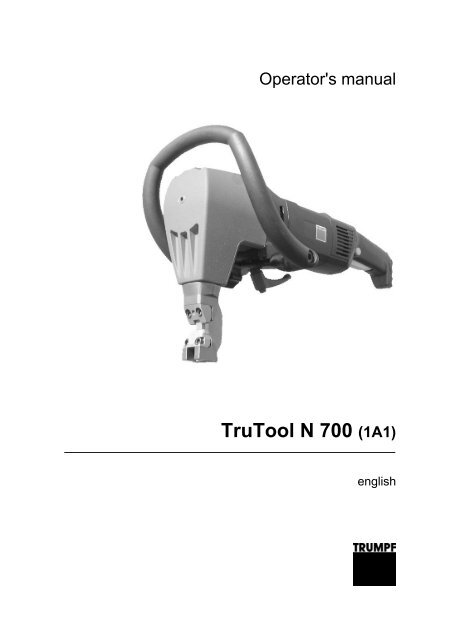
Operator's manual<br />
<strong>TruTool</strong> N <strong>700</strong> (1A1)<br />
english
Table of contents<br />
1. Safety ..................................................................................4<br />
1.1 General safety information...................................................4<br />
1.2 Specific safety information...................................................5<br />
2. Description .........................................................................6<br />
2.1 Intended use ........................................................................7<br />
2.2 Technical data .....................................................................8<br />
2.3 Noise and vibration information ...........................................9<br />
3. Setting work .................................................................... 11<br />
3.1 Selecting a die .................................................................. 11<br />
3.2 Selecting a punch ............................................................. 13<br />
3.3 Setting the penetration depth ........................................... 14<br />
3.4 Selecting and attaching a handle ..................................... 15<br />
3.5 Rotating the motor handle ................................................ 17<br />
4. Operation......................................................................... 18<br />
4.1 Working with the <strong>TruTool</strong> N <strong>700</strong> ....................................... 18<br />
4.2 Changing the cutting direction .......................................... 19<br />
4.3 Nibbling with templates..................................................... 20<br />
4.4 Making interior cutouts...................................................... 20<br />
5. Maintenance .................................................................... 21<br />
5.1 Replacing the tool ............................................................. 22<br />
Changing the punch .................................................... 23<br />
Changing the die and punch guide.............................. 23<br />
5.2 Regrinding the punch........................................................ 24<br />
5.3 Changing the wearing plate.............................................. 25<br />
5.4 Replacing carbon brushes................................................ 25<br />
6. Original accessories, wearing parts and<br />
optional items ................................................................. 26<br />
6.1 Ordering wearing parts and optional items....................... 27<br />
7. Appendix: Guarantee, declaration of<br />
conformity, replacement parts lists.............................. 28<br />
E528_05 2010-06-09 Table of contents 3
1. Safety<br />
1.1 General safety information<br />
• Read the operator's manual and safety information in their entirety<br />
before starting up the machine. Closely follow the instructions<br />
given.<br />
• Adhere to the safety regulations in accordance with DIN VDE,<br />
CEE, AFNOR and to the specific regulations of the country of<br />
operation.<br />
DANGER<br />
Risk of fatal injury due to electric shock<br />
‣ Remove the plug from the plug socket before undertaking<br />
any maintenance work on the machine<br />
‣ Check the plug, cable and machine for damage each time<br />
before using the machine.<br />
‣ Keep the machine dry and do not operate it in damp rooms.<br />
‣ Connect the fault current (FI) circuit breaker with a maximum<br />
breaking current of 30 mA when using the electric tool outside.<br />
WARNING<br />
Risk of injury due to improper handling<br />
‣ Wear safety glasses, hearing protection, protective gloves<br />
and work shoes when working at the machine.<br />
‣ Do not insert the plug unless the machine is switched off.<br />
After use, pull out the power plug.<br />
4 Safety 2010-06-09 E528_05
1.2 Specific safety information<br />
Note<br />
Make sure that the tool is connected to an electrical circuit that is<br />
protected with a slow-blow fuse (min. 15 A).<br />
WARNING<br />
Risk of injury to hands.<br />
‣ Do not reach into the processing line with your hands.<br />
‣ Use both hands to hold the machine.<br />
WARNING<br />
Risk of injury from hot and sharp chips!<br />
Chips exit the chip ejector at high speed.<br />
‣ Use the chip box.<br />
CAUTION<br />
Risk of injury due to improper handling<br />
The machine will be damaged or destroyed.<br />
‣ Do not use the cable to carry the machine.<br />
‣ Always lay the electrical cable above and away from the back<br />
of the machine and do not pull it over sharp edges.<br />
‣ Have servicing and inspections of handheld electric tools carried<br />
out by a qualified specialist. Only use original TRUMPF<br />
accessories.<br />
E528_05 2010-06-09 Safety 5
2. Description<br />
1 Bow-handle (mountable in 2 7 Die carrier<br />
positions)<br />
2 Eccentric shaft 8 Locking mechanism for die carrier<br />
3 Punch guide 9 Clamping lever for fastening the<br />
handle<br />
4 Punch 10 On/off switch<br />
5 Die 11 Release inhibiter knob<br />
6 Chip ejector<br />
Fig. 38379<br />
6 Description 2010-06-09 E528_05
2.1 Intended use<br />
WARNING<br />
Risk of injury due to improper handling<br />
‣ Only use the machine for work and materials as described<br />
under "Intended use."<br />
The TRUMPF Nibbler <strong>TruTool</strong> N <strong>700</strong> is an electrically operated<br />
hand-held device for:<br />
• Cutting of plate-shaped workpieces made of a punchable material<br />
such as steel, aluminum, non-ferrous heavy metal and<br />
plastic.<br />
• Cutting of tubes and machining of edged sheet profiles and/or<br />
press brake bendings e.g. for tanks, crash barriers, troughs<br />
etc.<br />
• Nibbling of straight or curved exterior and interior cutouts.<br />
• Nibbling along scribed lines or templates.<br />
Note<br />
The nibbling process produces cutting edges free of deformations.<br />
E528_05 2010-06-09 Description 7
2.2 Technical data<br />
Other countries<br />
Voltage 230 V 120 V 110 V 120 V<br />
Frequency 50/60 Hz 50/60 Hz 50 Hz 50/60 Hz<br />
Max. material thickness:<br />
7.0 mm 7.0 mm 7.0 mm 0.28 in<br />
Steel 400 N/mm 2<br />
Max. material thickness:<br />
5.0 mm 5.0 mm 5.0 mm 0.2 in<br />
Steel 600 N/mm 2<br />
Max. material thickness:<br />
3.5 mm 3.5 mm 3.5 mm 0.14 in<br />
Steel 800 N/mm 2<br />
Max. material thickness:<br />
10 mm 10 mm 10 mm 0.4 in<br />
Aluminum 250 N/mm 2<br />
Working speed 1.3 m/min 1.1 m/min 1.1 m/min 3.6 ft/min<br />
Nominal power consumption 1600 W 1500 W 1500 W 1500 W<br />
Current input 7.4 A 13.5 A 14.4 A 13.5 A<br />
Idle stroke rate 440/min 470/min 440/min 470/min<br />
Weight 8.3 kg 8.3 kg 8.3 kg 15.4 lbs<br />
Cutting track width 11 mm 11 mm 11 mm 0.472 in<br />
Starting hole diameter for die 60 mm 60 mm 60 mm 2.95 in<br />
Sheet profiles 90° inner bending radius<br />
USA<br />
min. 10 mm min. 10 mm min. 10 mm 0.4 in<br />
Smallest radius for curved cutouts 135 mm 135 mm 135 mm 5.3 in<br />
Distance to the template 11 mm 11 mm 11 mm 0.433 in<br />
Protective insulation Class II Class II Class II Class II<br />
Tab. 1<br />
8 Description 2010-06-09 E528_05
2.3 Noise and vibration information<br />
WARNING<br />
Vibration emission value may be exceeded.<br />
‣ Select tools correctly and replace them promptly when they<br />
show wear.<br />
‣ Have maintenance and repair work performed by trained<br />
specialist technicians.<br />
‣ Establish additional safety precautions for the protection of<br />
the operator against the effects of vibrations (e.g. keeping<br />
hands warm and organizing the work sequences).<br />
WARNING<br />
Noise emission value may be exceeded.<br />
‣ Wear hearing protection.<br />
CAUTION<br />
Vigorous upward and downward movements (hammering)<br />
due to unsuitable die.<br />
Excessive tool wear and increasing loads on the machine.<br />
‣ Use dies with the greatest height possible (keep distance X,<br />
shown in the drawing below, as small as possible).<br />
Notes<br />
• The specified vibration emission value was measured in accordance<br />
with a standardized testing procedure and can be<br />
used to compare one electric tool with another.<br />
• The specified vibration emission value can also be applied for<br />
a provisional estimate of the vibration load.<br />
• Times during which either the device is switched off or running<br />
but not actually in use can considerably reduce the vibration<br />
load during the entire working period.<br />
E528_05 2010-06-09 Description 9
Designation of measured value Unit Value in<br />
accordance<br />
with<br />
EN 60745<br />
Vibration emission value a h (vector sum of<br />
three directions)<br />
m/s 2 12<br />
Uncertainty K for vibration emission value m/s 2 2.7<br />
A-class acoustic pressure level L PA typically dB (A) 89<br />
A-class acoustic power level L WA typically dB (A) 100<br />
Uncertainty K for noise emission value dB 3<br />
Tab. 2<br />
10 Description 2010-06-09 E528_05
3. Setting work<br />
3.1 Selecting a die<br />
CAUTION<br />
Vigorous upward and downward movements (hammering)<br />
due to unsuitable die.<br />
Excessive tool wear and increasing loads on the machine.<br />
‣ Use dies with the greatest height possible (keep distance X,<br />
shown in the drawing below, as small as possible).<br />
1 Die (see following table) W Workpiece<br />
5 Punch guide X Distance between sheet surface<br />
and punch guide<br />
9 Punch<br />
Fig. 16802<br />
Depending on the thickness, tensile strength and type of the workpiece,<br />
one of the following types of die can be selected for the<br />
machining process:<br />
E528_05 2010-06-09 Setting work 11
Material<br />
Type of die<br />
Type of die<br />
Type of die<br />
5<br />
7<br />
P7<br />
-<br />
Mat. no.<br />
0098723<br />
Mat. no.<br />
0098722<br />
Mat. no.<br />
0098721<br />
>7-10<br />
Material thickness in mm for flat workpieces<br />
Aluminum -5 >5-7<br />
250 N/mm 2<br />
Mild steel -5 >5-7 -<br />
400 N/mm 2<br />
Stainless steel -5 - -<br />
600 N/mm 2<br />
Stainless steel -2.5 - -<br />
800 N/mm 2<br />
Material thickness in mm for profiles with press brake bending up to<br />
90°<br />
Aluminum -3 >3-5 >5-7<br />
250 N/mm 2<br />
Mild steel -3 >3-5 >5-7<br />
400 N/mm 2<br />
Stainless steel -3 >3-5 -<br />
600 N/mm 2<br />
Stainless steel<br />
800 N/mm 2 -2.5 - -<br />
Tab. 3<br />
12 Setting work 2010-06-09 E528_05
3.2 Selecting a punch<br />
2 different punches are available for machining sheets of different<br />
tensile strengths:<br />
Components Standard punch Punch for high-tensile<br />
steels<br />
Order no. 104589 104590<br />
Aluminum 250 N/mm 2 x -<br />
Mild steel 400 N/mm 2 x -<br />
Stainless steel<br />
- x<br />
600 N/mm 2<br />
Stainless steel<br />
800 N/mm 2 - x<br />
Tab. 4<br />
E528_05 2010-06-09 Setting work 13
3.3 Setting the penetration depth<br />
Note<br />
A greater penetration depth causes less vibrations, but a greater<br />
effort is required when pushing the machine forward and the service<br />
life of the punch is reduced.<br />
1 Eccentric shaft 4 Locking mechanism<br />
2 Die carrier E Penetration depth<br />
3 Punch<br />
Fig. 38378<br />
1. Rotate the eccentric shaft (1) until the punch (3) has reached<br />
its maximum penetration depth.<br />
2. Open the locking mechanism (4).<br />
14 Setting work 2010-06-09 E528_05
Note<br />
One rotation of 360° corresponds to a height adjustment of<br />
1.75 mm.<br />
3. Rotate the die carrier (2) by 360° as often as needed until the<br />
punch penetration depth of 1-3 mm has been achieved.<br />
4. Close the locking mechanism (4).<br />
3.4 Selecting and attaching a handle<br />
The suitable handle can be chosen depending on the application.<br />
Two types of handle are available:<br />
• Bow-handle<br />
• Compact handle<br />
1 Bow-handle 3 Clamping lever<br />
2 Motor handle<br />
Bow-handle <strong>TruTool</strong> N <strong>700</strong> Fig. 54785<br />
The bow-handle provides optimum handle positioning at all working<br />
heights. In combination with the motor handle, the weight of the<br />
machine is distributed over both handles.<br />
E528_05 2010-06-09 Setting work 15
1 Compact handle 3 Clamping lever<br />
2 Motor handle<br />
Compact handle <strong>TruTool</strong> N <strong>700</strong> Fig. 54786<br />
The compact handle is developed for application in situations<br />
where space is limited (e.g. profile machining). Moreover it is made<br />
out of steel and is heat resistant.<br />
Attaching the handle<br />
Swiveling the handle<br />
1. Attach the handle to the machine without a tool, using the<br />
clamping lever (3) for assistance.<br />
Note<br />
Each handle can be clamped in 2 positions using indexing.<br />
2. Rotate the clamping lever (3) approx. 2 full turns.<br />
3. Swivel the handle.<br />
4. Fix the clamping lever (3) in place.<br />
16 Setting work 2010-06-09 E528_05
3.5 Rotating the motor handle<br />
CAUTION<br />
Damage to property due to dust being drawn into the ventilation<br />
slots<br />
‣ Rotate the motor handle so that no dust can be drawn in at<br />
the air suction point.<br />
1 Release knob 3 On/off switch<br />
2 Release inhibiter knob<br />
Fig. 38394<br />
For applications where the machine is used at a 90° tilt, it is beneficial<br />
to rotate the handle accordingly.<br />
1. Press down the release knob (1).<br />
2. Rotate the handle (± 90°).<br />
3. Release the release knob (1).<br />
4. Click the handle into place by turning it slightly.<br />
E528_05 2010-06-09 Setting work 17
4. Operation<br />
4.1 Working with the <strong>TruTool</strong> N <strong>700</strong><br />
WARNING<br />
Risk of injury due to improper handling<br />
‣ Make sure the machine is always in a stable position when<br />
operating it.<br />
‣ Never touch the tool while the machine is running.<br />
‣ Always operate the machine away from your body.<br />
‣ Do not operate the machine above your head.<br />
CAUTION<br />
Damage to property due to excessively high line voltage<br />
Motor damage<br />
‣ Check the line voltage. The power supply voltage must correspond<br />
to the information on the nameplate of the machine.<br />
‣ When using an extension cord that is longer than 5 m, the<br />
cord must have a line diameter of at least 2.5 mm².<br />
The cutting result is improved and the service life of the punch increased<br />
if the cutting track is coated with oil before machining the<br />
workpiece.<br />
Material<br />
Oil<br />
Steel<br />
Punching and nibbling oil, order<br />
no. 103387<br />
Aluminum Wisura oil, order no. 125874<br />
Recommendations for oil Tab. 5<br />
1 Release inhibiter knob 2 On/off switch<br />
Fig. 38380<br />
18 Operation 2010-06-09 E528_05
Switching on<br />
Machining the material<br />
Switching off<br />
1. Either<br />
‣ To switch the machine to continuous operation:<br />
– Hold down the release inhibiter knob (1) and press the<br />
on/off switch (2).<br />
– Release the on/off switch (2).<br />
The switch remains engaged. The motor is running.<br />
or<br />
‣ To switch the machine to instantaneous connection:<br />
– Hold down the release inhibiter knob (1) and press the<br />
on/off switch (2).<br />
– Release the release inhibiter knob (1).<br />
The motor is running.<br />
2. When full speed has been reached: move the machine towards<br />
the workpiece.<br />
3. Machine the desired cutting line.<br />
4. In the event that the cutting track ends in the sheet: pull the<br />
machine (still running) a few millimeters back towards where<br />
the cutting track has already been cut open<br />
5. Press and release the on/off switch (2).<br />
4.2 Changing the cutting direction<br />
In situations where space is limited, the tool can be mounted in<br />
such a way as to have a different cutting direction<br />
• For cutting profiles: mount the tool at an angle of 90° either to<br />
the left or to the right.<br />
• For nibbling to the rear: mount the tool at an angle of 180°.<br />
1. Open the locking mechanism (8).<br />
2. Rotate the die carrier (7) in the desired direction.<br />
3. Close the locking mechanism (8).<br />
4. Check the penetration depth of the punch.<br />
E528_05 2010-06-09 Operation 19
4.3 Nibbling with templates<br />
The following requirements must be met when nibbling with templates:<br />
• The template must be at least 5 mm thick.<br />
• There must be a clearance of 11 mm between the contour of<br />
the template and the contour to be nibbled out.<br />
• The nibbler must be guided in such a way that the exterior cutout<br />
of the punch guide (5) always remains up against the template.<br />
• Observe a minimum bending radius of 135 mm.<br />
4.4 Making interior cutouts<br />
‣ Make a start hole at least 60 mm in diameter.<br />
20 Operation 2010-06-09 E528_05
5. Maintenance<br />
DANGER<br />
Risk of fatal injury due to electric shock<br />
‣ Pull the plug out of the socket whenever tools have to be replaced<br />
or prior to maintenance work on the machine.<br />
WARNING<br />
Risk of injury due to incorrect repair work<br />
Machine does not work properly.<br />
‣ Have maintenance and repair work performed by trained<br />
specialist technicians.<br />
CAUTION<br />
Damage to property caused by blunt tools.<br />
Machine overload.<br />
‣ Check the cutting edge of the cutting tool for wear every<br />
hour. Sharp cutting tools provide good cutting performance<br />
and are easier on the machine. Replace the cutting tool<br />
promptly.<br />
Maintenance point Procedure and interval Recommended lubricants Lubricant order no.<br />
Punch, die and wearing Check hourly - -<br />
parts<br />
Punch Regrind/replace as needed - -<br />
Ventilation slots/grid Clean as needed - -<br />
Die Change as needed - -<br />
Wearing plate Change as needed - -<br />
Punch and die carrier With each tool change Lubricating grease "G1" -<br />
Gearbox and gear head Have a qualified technician<br />
relubricate or replace the<br />
lubricating grease every<br />
300 operating hours.<br />
Lubricating grease "G1" 139440<br />
Maintenance positions and maintenance intervals Tab. 6<br />
E528_05 2010-06-09 Maintenance 21
5.1 Replacing the tool<br />
Note<br />
When the punch or die is blunt, or the punch cannot be reground,<br />
the tools must be replaced.<br />
1 Locking mechanism 5 Punch guide<br />
2 Punch 6 Screws for fastening the die and<br />
punch guide<br />
3 Die carrier 7 Die<br />
4 Wearing plate<br />
Fig. 38381<br />
22 Maintenance 2010-06-09 E528_05
Changing the punch<br />
1. Undo the locking mechanism (1).<br />
2. Rotate the die carrier (3) by 45°.<br />
3. Pull die carrier (3) out towards the bottom.<br />
4. Screw out the punch (2).<br />
Note<br />
Use lubricating grease "G1" for lubrication (TRUMPF order<br />
no. 139440).<br />
5. Lightly lubricate the square part of the punch and the die carrier<br />
bore hole.<br />
6. Align the punch to 45°.<br />
7. Check the penetration depth of the punch.<br />
8. Close the locking mechanism (1).<br />
Changing the die and punch guide<br />
1. Unscrew and remove the screws (6).<br />
2. Clean the support areas on the die carrier (3).<br />
3. Clean the replacement parts if necessary.<br />
Note<br />
Use lubricating grease "G1" for lubrication (TRUMPF order<br />
no. 139440).<br />
4. Lubricate the guide surfaces of the punch guide.<br />
Note<br />
Use original screws only.<br />
5. Tighten the screws (6) (torque 20 Nm).<br />
E528_05 2010-06-09 Maintenance 23
5.2 Regrinding the punch<br />
Notes<br />
• Dies cannot be reground.<br />
• Use original replacement parts only.<br />
• The punch can be reground by a total of approx. 10 mm. Observe<br />
a minimum length of 89 cm: shorter punches must be<br />
replaced (risk of collision).<br />
Fig. 9432<br />
1. Regrind the grinding surface in accordance with the diagram,<br />
making sure that it is well-cooled during the process.<br />
2. Lightly apply fine-grained oil stone to the cutting edge.<br />
24 Maintenance 2010-06-09 E528_05
5.3 Changing the wearing plate<br />
The wearing plate protects the die carrier against excessive wear.<br />
Note<br />
Excessive wearing can overload the machine and lead to a worsening<br />
of the cutting quality.<br />
1 Raised part 2 Depression<br />
Fig. 9468<br />
The wearing plate must be replaced when:<br />
• The raised part (1) is worn down.<br />
• The depression (2) is no longer visible.<br />
5.4 Replacing carbon brushes<br />
The motor comes to a standstill whenever the carbon brushes are<br />
worn out.<br />
Notes<br />
• Use original replacement parts only.<br />
• Observe the information on the rating plate.<br />
‣ Have the carbon brushes checked and replaced as required by<br />
a qualified technician.<br />
E528_05 2010-06-09 Maintenance 25
6. Original accessories, wearing parts<br />
and optional items<br />
- Supplied original<br />
accessories<br />
Wearing part Optional Order no.<br />
Punch (standard) x x - 0104589<br />
Punch for high-tensile sheets - x x 0104590<br />
Die 5 - x x 0098723<br />
Die 7 x x - 0098722<br />
Die P7 - x x 0098721<br />
Wearing plate x x - 0119173<br />
Bow-handle, complete x - - 1279590<br />
Compact handle, complete x - - 1279618<br />
Case x - - 1279611<br />
Punching and nibbling oil for steel (0.5 l) x x - 0103387<br />
Punching and nibbling oil for aluminum (1 l) - - x 0125874<br />
Allen key DIN 911-5 x - - 0067857<br />
Lubricating grease "G1" tube (25 g) x - - 0344969<br />
Lubricating grease "G1" can (900 g) - - x 0139440<br />
Operator's manual x - - 1277783<br />
Safety information (red document), other countries<br />
x - - 0125699<br />
Safety information (red document), USA x - - 1239438<br />
Chip bag - - x 0109275<br />
Tab. 7<br />
26 Original accessories, wearing parts and optional items 2010-06-09 E528_05
6.1 Ordering wearing parts and optional<br />
items<br />
Note<br />
The following data must be specified in order to ensure that parts<br />
are delivered correctly and without delay.<br />
1. Specify the order number.<br />
2. Enter further order data:<br />
– Voltage data<br />
– Quantity<br />
– Machine type<br />
3. Specify the complete shipping information:<br />
– Correct address.<br />
– Desired delivery type (e.g. air mail, courier, express mail,<br />
ordinary freight, parcel post).<br />
Note<br />
For TRUMPF service addresses, see<br />
www.trumpf-powertools.com.<br />
4. Send the order to the TRUMPF representative office.<br />
E528_05 2010-06-09 Original accessories, wearing parts and optional items 27
7. Appendix: Guarantee, declaration of<br />
conformity, replacement parts lists<br />
28 Appendix: Guarantee, declaration of conformity,<br />
replacement parts lists<br />
2010-06-09 E528_05