D4120 Duct Smoke Detector D4S Sensor ... - Fire-Lite Alarms
D4120 Duct Smoke Detector D4S Sensor ... - Fire-Lite Alarms
D4120 Duct Smoke Detector D4S Sensor ... - Fire-Lite Alarms

Create successful ePaper yourself
Turn your PDF publications into a flip-book with our unique Google optimized e-Paper software.
[5.3.2] For square top-over-bottom mounting<br />
configuration or <strong>D4S</strong> sensor component mounting:<br />
Center punch at (4) target centers: (2) “A” for sampling tubes and (2) “C” for<br />
the square configuration mounting tabs as shown on mounting template. Drill<br />
pilot holes at target “A” centers and cut two 1.375 inch diameter holes using<br />
a 1 3 /8 inch hole saw or punch. Drill .156 inch diameter holes using a 5 /32 inch<br />
drill at target “C” centers. If desired, drill an additional .156 inch hole at the<br />
location of one of the mounting tabs on the lower housing.<br />
[5.4] Secure the <strong>Duct</strong> <strong>Detector</strong> to the <strong>Duct</strong><br />
Use two (rectangular configuration) or three (square configuration) of the provided<br />
sheet metal screws to screw the duct detector to the duct.<br />
CAUTION: Do not overtighten the screws.<br />
[6] Sampling Tube Installation<br />
[6.1] Sampling Tube Selection<br />
The sampling tube must be purchased separately. Order the correct length,<br />
as specified in Table 1, for width of the duct where it will be installed. It is<br />
recommended that the sampling tube length extend at least 2 /3 across the duct<br />
width for optimal performance.<br />
Table 1. Sampling tubes recommended for different<br />
duct widths:<br />
Outside <strong>Duct</strong> Width<br />
Up to 1 ft.<br />
Sampling Tube Recommended*<br />
DST1<br />
1 to 2 ft. DST1.5<br />
2 to 4 ft. DST3<br />
4 to 8 ft. DST5<br />
8 to 12 ft. DST10 (2-piece)<br />
*Must extend a minimum of 2 /3 the duct width. These sampling tubes can<br />
only be used with new InnovairFlex duct smoke detectors.<br />
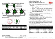
The sampling tube is always installed with the air inlet holes facing into the<br />
air flow. To assist proper installation, the tube’s connector is marked with an<br />
arrow. Make sure the sampling tube is mounted so that the arrow points into<br />
the airflow as shown in Figure 3. Mounting the detector housing in a vertical<br />
orientation is acceptable provided that the air flows directly into the sampling<br />
tube holes as indicated in Figure 3. The sampling tube and exhaust tube<br />
can be mounted in either housing connection as long as the exhaust tube is<br />
mounted downstream from the sampling tube.<br />
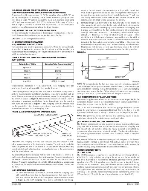
Figure 3. Air duct detector sampling tube:<br />
SAMPLING TUBE ENDCAP<br />
ARROW MUST FACE<br />
INTO AIR FLOW<br />
AIR FLOW<br />
DIRECTION<br />
H0551-00<br />
CAUTION: The sampling tube end cap, included with the detector, is critical<br />
to proper operation of the duct smoke detector. The end cap is needed to<br />
create the proper air flow to the sensor of the duct smoke detector. Once any<br />
sampling tube length adjustments are made, plug the end of the sampling tube<br />
with the provided end cap.<br />
A plastic exhaust tube is included with the unit to be installed if needed. Install<br />
into the housing connection that is downstream from the sampling tube<br />
connection. The exhaust tube can be installed from the front or back of the<br />
detector. A longer 1 foot exhaust tube, model ETX, is available as an accessory<br />
in cases where the molded exhaust tube does not extend at least 2 inches into<br />
the duct.<br />
[6.2] Sampling Tube Installation<br />
1. For tubes shorter than the width of the duct, slide the sampling tube,<br />
with installed end cap, into the housing connection that meets the airflow<br />
first. Position the tube so the arrow points into the airflow as shown<br />
in Figure 3. Per NFPA sampling tubes over 3 feet long should be supported<br />
at the end opposite the duct detector. In ducts wider than 8 feet,<br />
work must be performed inside the duct to couple the other section of<br />
the sampling tube to the section already installed using the 1 /2 inch conduit<br />
fitting. Make sure that the holes on both sections of the air inlet<br />
sampling tube are lined up and facing into the airflow.<br />
2. For tubes longer than the width of the duct, the tube should extend out<br />
of the opposite side of the duct. Drill a 3 /4 inch hole in the duct opposite<br />
the hole already cut for the sampling tube. Ensure that the sampling tube<br />
is angled downward from the duct smoke detector to allow for moisture<br />
drainage away from the detector. The sampling tube should be angled<br />
at least 1/4” downward for every 12” of duct width per Figure 4. There<br />
should be 10 to 12 holes spaced as evenly as possible across the width of<br />
the duct. If there are more than 2 holes in the section of the tube extending<br />
out of the duct, select a shorter tube using Table 1. Otherwise, trim<br />
the tube to leave approximately 1 to 2 inches extending outside the duct.<br />
Plug the end with the end cap and tape closed any holes in the protruding<br />
section of tube. Be sure to seal the duct where the tube protrudes.<br />
Figure 4.<br />
2˝<br />
3<br />
/4˝<br />
HOLE<br />
1<br />
/ 4˝<br />
12˝<br />
DETECTOR<br />
H0215-00<br />
NOTE: Air currents inside the duct may cause excessive vibration, especially<br />
when the longer sampling tubes are used. In these cases, a 3 inch floor flange<br />
(available at most plumbing supply stores) may be used to fasten the sampling<br />
tube to the other side of the duct. When using the flange/connector mounting<br />
technique, drill a 1 to 1 /4 inch hole where the flange will be used.<br />
[6.3] Modifications of Sampling Tubes<br />
There may be applications where duct widths are not what is specified for the<br />
installation. In such cases, it is permissible to modify a sampling tube that is<br />
longer than necessary to span the duct width.<br />
Use a 0.193 inch diameter (#10) drill and add the appropriate number of holes<br />
so that the total number of holes exposed to the air flow in the duct is 10 to 12.<br />
Space the additional holes as evenly as possible over the length of the tube.<br />
NOTE: This procedure should only be used as a temporary fix and is not intended<br />
as a substitute for ordering the correct length tubes.<br />
[6.4] Remote Sampling Tube Installation<br />
The detector arrangement can also incorporate remote mounting of the sampling<br />
tube and/or exhaust tube. In this case both the detector, sampling tube<br />
and exhaust tube (if included) should be rigidly mounted to withstand the<br />
pressure and vibrations caused by the air velocity. The location of the detector’s<br />
sampling tube should be such that there is uniform airflow in the cross<br />
section area.<br />
The pressure differential across the sampling and exhaust ports in the detector<br />
housing shall be verified to be between 0.01 and 1.11 inches of water. Do so<br />
by measuring the pressure difference between the inlet and outlet ports on the<br />
detector housing using a manometer as described in Section 7.1.<br />
[7] Measurement tests<br />
[7.1] air flow<br />
The <strong>D4120</strong> is designed to operate over an extended air speed range of 100 to<br />
4000 FPM. To verify sufficient sampling of ducted air, turn the air handler on<br />
and use a manometer to measure the differential pressure between the two<br />
sampling tubes. The differential pressure should measure at least 0.01 inches<br />
of water and no more than 1.11 inches of water. Because most commercially<br />
available manometers cannot accurately measure very low pressure differentials,<br />
applications with less than 500 FPM of air speed may require one of the<br />
following: 1) the use of a current-sourcing pressure transmitter (Dwyer Series<br />
607) per Section 7.2, or 2) the use of aerosol smoke per section 12.5.3.<br />
SS-300-000 3 I56-2967-002R