view installation note - Pertronic Industries Ltd
view installation note - Pertronic Industries Ltd
view installation note - Pertronic Industries Ltd

You also want an ePaper? Increase the reach of your titles
YUMPU automatically turns print PDFs into web optimized ePapers that Google loves.
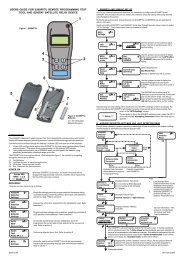
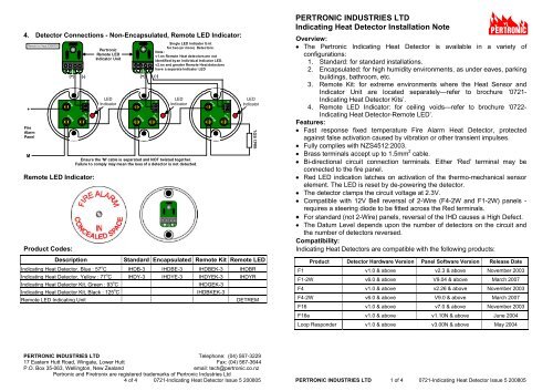
4. Detector Connections - Non-Encapsulated, Remote LED Indicator:Remote Ind Heat 20080509+FireAlarmPanelMRed RedBlack+1 2 3(+)(-)Remote LED Indicator:Product Codes:+Description-<strong>Pertronic</strong>Remote LEDIndicator UnitLEDIndicator+1 2 3(+)Red RedBlackSingle LED Indicator Unitfor two (or more) Detectors.Note:v1.nn Remote Heat dete ctors are notidentified by an individual Indicator LED.v2.nn and greater Remote Heat detectorshave a separate Indicator LEDEnsure the 'M' cable is separated and NOT twisted together.Failure to comply may mean the loss of a detector is not detected.(-)+-LEDIndicatorRed RedBlack+-LEDIndicatorStandard Encapsulated Remote Kit Remote LEDIndicating Heat Detector, Blue : 57 o C IHDB-3 IHDBE-3 IHDBEK-3 IHDBRIndicating Heat Detector, Yellow : 77 o C IHDY-3 IHDYE-3 IHDYEK-3 IHDYRIndicating Heat Detector Kit, Green : 93 o C IHDGEK-3Indicating Heat Detector Kit, Black : 125 o C IHDBKEK-3Remote LED Indicating Unit DETREM10k EOLPERTRONIC INDUSTRIES LTDIndicating Heat Detector Installation NoteOver<strong>view</strong>: The <strong>Pertronic</strong> Indicating Heat Detector is available in a variety ofconfigurations:1. Standard: for standard <strong>installation</strong>s.2. Encapsulated: for high humidity environments, as under eaves, parkingbuildings, bathroom, etc.3. Remote Kit: for extreme environments where the Heat Sensor andIndicator Unit are located separately—refer to brochure ‘0721-Indicating Heat Detector Kits’.4. Remote LED Indicator: for ceiling voids—refer to brochure ‘0722-Indicating Heat Detector-Remote LED’.Features: Fast response fixed temperature Fire Alarm Heat Detector, protectedagainst false activation caused by vibration or other transient impulses. Fully complies with NZS4512:2003. Brass terminals accept up to 1.5mm 2 cable. Bi-directional circuit connection terminals. Either ‘Red’ terminal may beconnected to the fire panel. Red LED indication latches on activation of the thermo-mechanical sensorelement. The LED is reset by de-powering the detector. The detector clamps the circuit voltage at 2.3V. Compatible with 12V Bell reversal of 2-Wire (F4-2W and F1-2W) panels -requires a steering diode to be fitted across the Red terminals. For standard (not 2-Wire) panels, reversal of the IHD causes a High Defect. The Datum Level depends upon the number of detectors on the circuit andthe number of detectors reversed.Compatibility:Indicating Heat Detectors are compatible with the following products:Product Detector Hardware Version Panel Software Version Release DateF1 v1.0 & above v2.3 & above November 2003F1-2W v6.0 & above V9.04 & above March 2007F4 v1.0 & above v2.26 & above November 2003F4-2W v6.0 & above V9.0 & above March 2007F16 v1.0 & above v7.0 & above November 2003F16e v1.0 & above v1.10N & above June 2004Loop Responder v1.0 & above v3.00N & above May 2004PERTRONIC INDUSTRIES LTD Telephone: (04) 567-322917 Eastern Hutt Road, Wingate, Lower Hutt Fax: (04) 567-3644P.O. Box 35-063, Wellington, New Zealand email: tech@pertronic.co.nz<strong>Pertronic</strong> and Firetronix are registered trademarks of <strong>Pertronic</strong> <strong>Industries</strong> <strong>Ltd</strong>4 of 4 0721-Indicating Heat Detector Issue 5 200805 PERTRONIC INDUSTRIES LTD 1 of 4 0721-Indicating Heat Detector Issue 5 200805
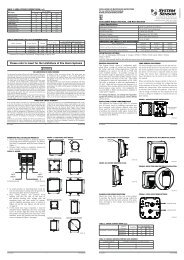
1. Detector Connections - Non-Encapsulated:2. Detector Connections - Encapsulated:Encap Ind Heat 20080507+Fire AlarmPanelMRedBlackBlac kRedEns ure the 'M' cable is separated and NOT twisted together at e ach detector input.Failure to com ply m ay m ean the loss of a de tector is no t detectedRedBlackBlackRed10k EOL3. Detector Connections - Indicating Heat Detector Kit:Over<strong>view</strong>: <strong>Pertronic</strong> Indicating Heat Detector Kits are available in a variety oftemperature settings to allow placement in very low or very high temperatureenvironments.Encapsulated Heat Sensor Unit: Available in four temperature settings:○ Blue: encapsulated 57 0 C thermo-mechanical sensor element○ Yellow: encapsulated 77 0 C thermo-mechanical sensor element○ Green: encapsulated 93 0 C thermo-mechanical sensor element○ Black: encapsulated 125 0 C thermo-mechanical sensor element Fire rated cable connection to Alarm Indication UnitAlarm Indication Unit: Terminals accept up to 1.5mm 2 cable. Bi-directional circuit connection terminals. Either ‘Red’ terminal may beconnected to the fire panel. Red LED indication latches on activation of the thermo-mechanical sensorelement. The LED is reset by de-powering the detector. Note: the Alarm Indication Unit must be installed remotely from theEncapsulated Heat Sensor Unit.Encapsula ted Heat Sensor Unit:In sta l l e d Insi d e theExtreme Temperature AreaAlarm Indication UnitsIn stal l e d Insi d e th eAmbient Temperature AreaThermo-MechanicalSensor Element:'Blue' (57ºC)'Yellow' (77ºC)'Green' (93ºC)'Black' (1 25ºC)Extreme Temperature AreaAmbient Temperature Area3m Fire-Rated CableL ED IndicatorLED IndicatorFire AlarmPanelMEnsure the 'M' cable is s eparated and NOT tw isted together.Failure to comply may mean the loss of a dete ctor is not de tectedPERTRONIC INDUSTRIES LTD 2 of 4 0721-Indicating Heat Detector Issue 5 200805 PERTRONIC INDUSTRIES LTD 3 of 4 0721-Indicating Heat Detector Issue 5 200805+RedRedBlackRedRedBlack10k EOLInd Heat Det Kit 20080509