LaserFOCUS VLF-250 Product Guide - Pertronic Industries Ltd
LaserFOCUS VLF-250 Product Guide - Pertronic Industries Ltd
LaserFOCUS VLF-250 Product Guide - Pertronic Industries Ltd

Create successful ePaper yourself
Turn your PDF publications into a flip-book with our unique Google optimized e-Paper software.
Vision Fire & Security<strong>LaserFOCUS</strong><strong>VLF</strong>-<strong>250</strong><strong>Product</strong> <strong>Guide</strong>March 29, 2005Part: 20295
VESDA ®<strong>LaserFOCUS</strong> <strong>VLF</strong>-<strong>250</strong> <strong>Product</strong> <strong>Guide</strong>Copyright InformationThis document is protected by copyright under the laws of Australia and other jurisdictions throughout the world. It must not by any means,either in whole or part, be reproduced, communicated to the public, adapted, distributed, sold, modified, published except as permitted byany laws or statute or with prior written consent of VFS International Pty <strong>Ltd</strong>. Copyright 2004 VFS International Pty <strong>Ltd</strong> ACN 100 259 381DisclaimerThe manufacturer reserves the right to change designs or specifications without obligation and without further notice. VESDA,LaserTEKNIC, LaserPLUS, LaserSCANNER, LaserCOMPACT, <strong>LaserFOCUS</strong>, VESDAnet, VESDAlink, ASPIRE, ASPIRE2, AutoLearn,VSM, VConfig, InfoWORKS, PROACTIV, PRECISION, VSC, ADPRO, FastTrace, FastVu, FastScan, Axiom, PRO, Amux, Video Central,Millbank and VxLAN are brands and trade marks used under license by the distributor.FCC Compliance StatementThis equipment has been tested and found to comply with the limits for a Class B digital device, pursuant to part 15 of the FCC Rules.These limits are designed to provide reasonable protection against harmful interference in a residential installation. This equipmentgenerates, uses and can radiate radio frequency energy and, if not installed and used in accordance with the instruction, may causeharmful interference to radio communications. However, there is no guarantee that interference will not occur in a particular installation. Ifthis equipment does cause harmful interference to radio or television reception, the user is encouraged to try to correct the interference byone or more of the following measures; re-orientate or relocate the receiving antenna, increase the separation between the equipment andreceiver, connect the equipment to a power outlet which is on a different power circuit to the receiver or consult the dealer or anexperienced radio/television technician for help.General WarningThis product must only be installed, configured and used strictly in accordance with the General Terms and Conditions and the technicaldocumentation available from VFS International Pty <strong>Ltd</strong> (VFS). You acknowledge that you have read and agree to those terms andconditions. All proper health and safety precautions must be taken during the installation, commissioning and maintenance of the product.The product should not be connected to a power source until all the components have been installed. Proper safety precautions must betaken during tests and maintenance of the products when these are still connected to the power source. Failure to do so or tampering withthe electronics inside the products can result in an electric shock causing injury or death and may cause equipment damage. VFS is notresponsible and cannot be held accountable for any liability that may arise due to improper use of the equipment and/or failure to takeproper precautions. Only persons trained through an accredited VFS training course can install, test and maintain the product.Limitation of LiabilityThis product must only be installed, configured and used strictly in accordance with the General Terms and Conditions, this manual and thetechnical documentation available from VFS International Pty <strong>Ltd</strong>. You acknowledge that you have read and agree to those terms andconditions.You acknowledge that you have been provided with a reasonable opportunity to appraise the product and have made your ownindependent assessment of the fitness or suitability for your purpose. You acknowledge that you have not relied on any oral or writteninformation, representation or advice given by or on behalf of VFS or its representatives.VFS has no liability to you or any person for incidental or consequential loss, expense or damages including, without limitation, loss ofbusiness, loss of profits or loss of data. You indemnify VFS for any claim, amount or liability brought against VFS in connection with theproduct.You expressly agree that you assume the entire risk as to the results and performance of the product resulting from the configuration of theproduct. VFS does not warrant, guarantee or make any representations, either expressly or implied, regarding the current or future use, orthe results of the use, of the product, with respect to its correctness, accuracy, reliability, completeness, interworking, functionality,currentness or otherwise resulting from the configuration of the product.To the full extent permitted by law, VFS expressly excludes all conditions, warranties and liability, whether imposed or implied by statute orby rule of law or otherwise, which are not expressly set out in the General Terms and Conditions.To the extent permitted by law, your sole recourse for any defect of, damage to, or performance standard of the product will be under theexpress warranties the General Terms and Conditions (if applicable) and VFS will in no event be liable to pay any amount or damagesresulting from or in connection with the product.To the extent by law that any limitation or exclusion can not apply, the total liability of VFS in relation to the product is limited to:(i) in the case of services, the cost of having the services supplied again; or(ii) in the case of goods, the lowest cost of replacing the goods, acquiring equivalent goods or having the goods repaired.To the extent permitted by law, VFS has no liability with respect to damage to or arising out of, or the condition or performance of, theproduct resulting from (i) negligence or improper use, storage, installation, configuration commission, service maintenance or handling ofthe product (where 'improper' includes treatment other than in accordance with the product manual, these terms and conditions or theinformation provided at a training session); (ii) accident, unforeseeable circumstances or disaster; (iii) modifications to the product otherthan in accordance with VFS's instructions; (iv) attachment of or interoperation with features, software or products not approved by VFS inwriting; or (v) where the product has been serviced by persons not authorized by VFS in writing to service the product.<strong>Product</strong> Warranty ConditionsVFS International Pty <strong>Ltd</strong> (VFS) warrants that new products (excluding consumable items) will conform to its published specifications andremain in good working order during the warranty period of 24 (twenty four) months from the date an invoice is issued by VFS to itsdistributor.VFS also warrants that products serviced or repaired by its service department will remain in good working order for a warranty period of12 (twelve) months from the date of service. This service or repair warranty is only available on products less than 7 (seven) years old andonly covers those component parts of the products serviced, repaired or replaced.Should product under warranty not be in good working order, VFS will, at its option, either repair or replace the product or its componentparts at no additional charge.Spare parts and replacement product, covered under this warranty, will be furnished on an exchange basis and will, at the option of VFSeither be new, equivalent to new or reconditioned. Returned parts and products to VFS become the property of VFS.This warranty does not cover the repair or damage to the product resulting from or arising out of (i) negligence or improper use storage,installation, configuration, commission, service, maintenance or handling of the product (where 'improper' includes treatment other than inaccordance with any manual or instructions for use of the product); (ii) accident, unforeseeable circumstances or disaster; (iii)modifications to the product other than in accordance with VFS's instructions; (iv) attachment of features or interoperation with features,software or products not approved by VFS in writing; or (v) where the product has been serviced by persons not authorized by VFS inwriting to service the product.i
<strong>LaserFOCUS</strong> <strong>VLF</strong>-<strong>250</strong> <strong>Product</strong> <strong>Guide</strong> VESDA ®Document ConventionsThe following typographic conventions are used in this document.ConventionBoldItalicsDescriptionUsed to denote: emphasisUsed for names of menus, menu options, toolbar buttonsUsed to denote: references to other parts of this document orother documents. Used for the result of an actionThe following icons are used in this documentConventionDescriptionCaution: This icon is used to indicate that there is a danger toequipment. The danger could be loss of data, physical damage,or permanent corruption of configuration details.Warning: This icon is used to indicate that there is a danger ofelectric shock. This may lead to death or permanent injury.Warning: This icon is used to indicate that there is a danger ofinhaling dangerous substances. This may lead to death orpermanent injury.Contact UsAustralia and Asia The Americas Europe & Middle EastVision SystemsPrivate Bag 215495 Blackburn RoadMount Waverley VIC 3149AustraliaToll free: 1800 700 203Tel: +61 (0) 3 9211 7200Fax: +61 (0) 3 9211 7201Vision Systems700 Longwater DriveNorwell,Massachusetts, 02061USAToll free: 800 229 4434Tel: +1 78 740 2223Fax: +1 78 740 4433Vision SystemsVision House, Focus 31,Mark RoadHemel HempsteadHertfordshire HP2 7BWUnited KingdomTel: +44 (0) 1442 242 330Fax: +44 (0) 1442 249 327www.vesda.com www.adpro.com.au www.millbank.co.ukStandardsWe strongly recommend that this document is read in conjunction with the appropriate local codes and standards for smoke detection andelectrical connections. This document contains generic product information and some sections may not comply with all local codes andstandards. In these cases, the local codes and standards must take precedence. The information below was correct at time of printing butmay now be out of date, check with your local codes, standards and listings for the current restrictions.FDAThis VESDA product incorporates a laser device and is classified as a Class 1 laser product that complies with FDA regulations 21 CFR1040.10. The laser is housed in a sealed detector chamber and contains no serviceable parts. The laser emits invisible light and can behazardous if viewed with the naked eye. Under no circumstances should the detector chamber be opened.FM3611 Hazardous Approval Warning: Exposure to some chemicals may degrade the sealing of relays used on the detector. Relays used onthe detector are marked “TX2-5V”, “G6S-2-5V” or “EC2-5NU”.VESDA detectors must not be connected or disconnected to a PC while the equipment is powered in an FM Division 2 hazardous(classified) location (defined by FM 3611).ii
VESDA ®<strong>LaserFOCUS</strong> <strong>VLF</strong>-<strong>250</strong> <strong>Product</strong> <strong>Guide</strong>Codes and Standards Information for Air Sampling Smoke DetectionONORM F3014ONORM F3014, transport times for all tubes (including capillaries) must not exceed 60 seconds from any hole. This means that the predesignedpipe networks that include capillaries cannot be used.AS1603.8The performance of this product is dependent upon the configuration of the pipe network. Any extensions or modifications to the pipenetwork may cause the product to stop working correctly. You must check that ASPIRE2 approves alterations before making any changes.ASPIRE2 is available from your VESDA ASD distributor.AS1603.13AS1603.13: VESDA detectors are not compliant with the pressure testing in this standard.FM Approved ApplicationsThe product must be powered from VPS-100US-120, VPS-100US-220 or VPS-220 only.European InstallationsThe product must use a power supply conforming to EN54: Part 4.Listing Information for the VESDA <strong>LaserFOCUS</strong>UL ListingFor open area protection the fire alarm threshold (signal) that initiates an evacuation procedure via the Fire Alarm Panel must not be set noless sensitive than 0.625%/ft. The detector can send this signal either via the Fire Alarm Panel Output signal or the Pre-alarm outputsignal.ActivFire ListingThe fire alarm threshold (signal) that initiates an evacuation procedure via the Fire Alarm Panel must not be set no less sensitive than1%m.<strong>Product</strong> ListingsULULCFMLPCBVdS approval number G205018NFActivFireCCCPCE (EN 50130-4:1995 A2:2003 & EN 61000-6-3:2001)Document:07208_17iii
<strong>LaserFOCUS</strong> <strong>VLF</strong>-<strong>250</strong> <strong>Product</strong> <strong>Guide</strong> VESDA ®iv
VESDA ®Contents<strong>LaserFOCUS</strong> <strong>VLF</strong>-<strong>250</strong> <strong>Product</strong> <strong>Guide</strong>Scope ...............................................................................................................................................1Introduction to VESDA <strong>LaserFOCUS</strong> ............................................................................................1General notification .................................................................................................................1Installation .......................................................................................................................................1Detector mounting ...................................................................................................................1Installing the smoke detector ..................................................................................................2Installation procedure ..........................................................................................................3Inverting the user interface display .....................................................................................4Detector removal .....................................................................................................................4Air inlet pipe connections ........................................................................................................5Exhaust air pipe connections ..................................................................................................6Wiring connections ..................................................................................................................6Detector cabling requirements ............................................................................................6GPI – General Purpose Input (Terminals 1 & 2) .................................................................7Extra terminals (Terminals 3, 4, 5, 6 & 7) ............................................................................9Power supply (Terminals 8, 9, 10 & 11) ..............................................................................9Relays (Terminals 12 - 20) ................................................................................................10Typical Wiring To Fire Panel (FACP) ................................................................................11Wiring To an Address Loop Module. .................................................................................11Interface card ....................................................................................................................12RS232 Compatible serial port ...............................................................................................12Installation Checklist .............................................................................................................13Sampling Pipe Network Design ...................................................................................................13Single pipe network ...............................................................................................................14Branched pipe network .........................................................................................................16Return air sampling (return grilles) ........................................................................................17Installation considerations .....................................................................................................18Air sampling in a duct ............................................................................................................19Commissioning .............................................................................................................................19General .................................................................................................................................19AutoLearn Smoke .................................................................................................................20AutoLearn Flow .....................................................................................................................21VESDA System Configurator (VSC) .....................................................................................21Commissioning smoke test ...................................................................................................21Detector Overview .........................................................................................................................22Features ................................................................................................................................22Description ............................................................................................................................22Applications ...........................................................................................................................22<strong>Product</strong> Interface ...........................................................................................................................23Front view ..............................................................................................................................23Instant Recognition Display ...................................................................................................24Controls and indicators .........................................................................................................25Interface information and control buttons ..........................................................................26Detector control buttons ....................................................................................................27Smoke level & Instant Fault Finder displays .........................................................................28Smoke level display ..........................................................................................................29Instant Fault Finder ...........................................................................................................29<strong>VLF</strong> Troubleshooting with Instant Fault Finder .................................................................30v
<strong>LaserFOCUS</strong> <strong>VLF</strong>-<strong>250</strong> <strong>Product</strong> <strong>Guide</strong> VESDA ®Factory Defaults ............................................................................................................................ 31Specifications ................................................................................................................................ 32Maintenance .................................................................................................................................. 34Overview ............................................................................................................................... 34Maintenance schedule ..........................................................................................................35Filter replacement ................................................................................................................. 36Aspirator replacement ........................................................................................................... 37vi
VESDA ®1.1 Scope<strong>LaserFOCUS</strong> <strong>VLF</strong>-<strong>250</strong> <strong>Product</strong> <strong>Guide</strong>This manual describes the features of the VESDA <strong>LaserFOCUS</strong>, the specifications andfunctions, installation requirements, commissioning and operation procedures. A schedule forpreventative maintenance is also provided.1.2 Introduction to VESDA <strong>LaserFOCUS</strong>The VESDA <strong>LaserFOCUS</strong> early warning air sampling smoke detector incorporates world leadingVESDA very early warning laser based aspirated smoke detection technology. It provideslocalized fire risk management solutions for small, critical environments. The VESDA<strong>LaserFOCUS</strong> <strong>VLF</strong>-<strong>250</strong> monitors areas up to <strong>250</strong> m 2 (<strong>250</strong>0 sq. ft.), dependant on local codes andstandards. The VESDA <strong>LaserFOCUS</strong> complements the existing VESDA detector range and hasbeen designed to provide simple installation and commissioning, absolute smoke detection andreliable and consistent response to smoke events without being affected by false alarms.General notificationNote:Caution:Prior to carrying out any work or maintenance on the VESDA <strong>LaserFOCUS</strong> take thenecessary steps to advise the monitoring authority that power may be removed andthe system disabled.Electrostatic discharge precautions need to be taken prior to removing the frontcover from the detector otherwise damage may occur to the unit.1.3 InstallationThe VESDA <strong>LaserFOCUS</strong> detector is shipped with all the components necessary for installationwith the exception of pipe and associated materials.Components include:• 1 <strong>LaserFOCUS</strong> detector with fitted exhaust deflector.• 1 Mounting bracket.• 1 End of Line resistor (see GPI – General Purpose Input (Terminals 1 & 2) on page 7)• 2 M4 x 20 mm locking screws• this <strong>Product</strong> ManualCheck all components for damage and refer any concerns to your VESDA distributor.Note: Removing the rear cover of the detector will void your warranty.Note: Opening or removing the sealed laser detection chamber will void your warranty.Detector mountingThe VESDA <strong>LaserFOCUS</strong> can be installed upright, inverted or horizontally.Note: Ensure the smoke detector is mounted away from obstructions and below ceilinglevel.1
<strong>LaserFOCUS</strong> <strong>VLF</strong>-<strong>250</strong> <strong>Product</strong> <strong>Guide</strong> VESDA ®Caution:Caution:An exhaust deflector must be fitted for upright mounting, unless the exhaust port isconnected to a return air pipe.Do not install this unit on its side. There is a risk of particulate and condensationcollecting on critical elements of the detector chamber reducing the detectorsperformance.Ensure that there is sufficient clearance to mount the detector, noting the location of air samplingpipes and cable entry points. Owing to the rigid nature of the plastic pipe, installation mustprovide for sufficient movement in all pipework (air inlet, air exhaust and cable pipes) to allowpipe ends to be easily fitted and removed.ABCLegendABCMin. 200 mm (8 in.) below ceiling levelMin. 500 mm (20 in.) from a wall or obstruction to allow access to the security tabDo not install the detector on its sideFigure 1 - Mounting locationInstalling the smoke detectorIn all installation cases the mounting bracket must be fitted (upright) as shown in figure 2,“Mounting bracket orientation for upright and inverted mounting,” on page 3.Note:Ensure the mounting surface is flat. This will permit an air tight seal to be achievedbetween the sampling pipe and the tapered air ports on the detector.Warning:Prior to drilling the attachment holes for the mounting bracket, ensurethat all mounting surfaces (i.e. walls, cabinet sides, etc). are clear ofelectrical wiring and plumbing.Where the pipe network and cabling are already fitted, the bracket can be used to aid alignmentof the detector with the pipes. The Installation procedure below explains this process.2
VESDA ®Installation procedure<strong>LaserFOCUS</strong> <strong>VLF</strong>-<strong>250</strong> <strong>Product</strong> <strong>Guide</strong>Cut the air inlet pipe and exhaust pipe (if used) at 90 o , and to the same length (for normal andinverted mounting). Remove all rough edges. This is critical to obtain an air tight seal with thesmoke detector.1. Position the air inlet centerline mark (A), see Figure 2, of the mounting bracket against theend of the air inlet pipe.2. In the cut out section of the mounting bracket mark a line across the top of the cut out ifmetric size pipe is used or mark a line across the bottom of the cut out if Imperial size pipeis used.3. Slide the mounting bracket down (up for inverted mounting) until the top of the bracketaligns with the marked line.4. Mark off and drill the 2 bracket mounting holes (H).5. Screw the bracket to the wall.6. Hook the smoke detector onto the mounting bracket tabs and pull it down into place.7. Use the two M4 x 20 mm locking screws provided and screw them into the screw holes onthe left and right side of the detector. See the items marked (F) in the Figure Detectorremoval on page 5.8. The air sampling pipe can now be attached and power connected.(See section Wiring connections on page 19 for connection information).For inverted installation, to mark off the location of the mounting holes, follow steps 1 – 4 with themounting bracket inverted to that shown in figure 2, “Mounting bracket orientation for upright andinverted mounting,” on page 3. Also see Inverting the user interface display on page 4.ABCDDELegendFGHABCDEFAir inlet port centerlineExhaust air port centerlineCutoutCable entry centerlinesMounting tabMetric OD 25 mm pipe markJIGHImperial IPS ¾ in. pipe markBracket mounting holesICenterline of detectorJAnti-tamper clipFigure 2 - Mounting bracket orientation for upright and inverted mountingLegendACDABCSecurity tabFinger clipMounting tabBDAnti-tamper clipECenterline of detectorFigure 3 - Mounting bracket rear viewE3
<strong>LaserFOCUS</strong> <strong>VLF</strong>-<strong>250</strong> <strong>Product</strong> <strong>Guide</strong> VESDA ®Inverting the user interface displayCaution:Electrostatic discharge precautions need to be taken prior to removing the frontcover from the detector.For inverted mounting applications, the VESDA <strong>LaserFOCUS</strong> will require the user interfacedisplay to be turned through 180 o . This is carried out prior to installing the detector. Also seeMounting bracket orientation for upright and inverted mounting on page 3.Inverting the user interface display:1. Place the detector on its back, push in the securing tab and lift up the field service accessdoor. (See Figure 23, “Field Service Access Door security tab and clip,” on page 25).2. Remove the 2 retaining screws and lift off the main cover.3. Disconnect the restraining strap from the clip (C) and the ribbon cable from the userinterface card (B) and place the cover aside.4. Open the clips (E).5. Lift out the user interface display card, carefully turn it through 180 o and then clip it back intoplace.6. Reconnect the ribbon cable and the restraining strap.7. Replace the main cover and screw down the 2 retaining screws.8. Close the field service access door.The detector is now ready for inverted installation.ABECDEBFLegendA Ribbon cable clip D Interface cardB Ribbon cable connector E ClipC Retaining strap clip F Air filter cartridge cavityFigure 4 - Inside view of the front cover (as it would appear inverted)Detector removalCaution:Electrostatic discharge precautions need to be taken prior to removing the frontcover from the detector otherwise damage may occur to the unit.4
VESDA ®<strong>LaserFOCUS</strong> <strong>VLF</strong>-<strong>250</strong> <strong>Product</strong> <strong>Guide</strong>Note: Take the necessary steps to advise the monitoring authority of work being carriedout and that the system needs to be disabled.1. Turn off the power to the detector.2. Disconnect the sampling pipes.3. Push in the security tab and lift up the field service access door, see Figure 23, “FieldService Access Door security tab and clip,” on page 25.4. Unscrew the front cover retaining screws (E).5. Lift off and swing down the front cover, a restraining strap will take the load. For invertedmounted detectors the cover should be removed and placed aside.6. Disconnect all field wiring from the terminal block.7. Unscrew the two M4 x 20 mm locking screws on the left and right side of the detector. Seethe items marked (F) in the Figure Detector removal on page 58. Use a screw driver to push down the anti-tamper clip in hole (A), at the same time, push thedetector base up.9. Lift the detector off the mounting bracket.Once the detector has been removed re-fit the front cover to keep the internal components safefrom damage and the electrical cabling safe.Note:For inverted mounted detectors, the front cover will need to be removed prior tounhooking the detector from the mounting bracket. Disconnect the retaining strapand the ribbon cable from the user interface card and place the cover aside.BAFEEFDCLegendA Anti-tamper clip access hole D AspiratorB Dual stage air filter cartridge E Retaining screwC Terminal block F Bracket locking screw holesAir inlet pipe connectionsFigure 5 - Detector removalThe tapered shape of the air inlet port is designed to accept standard pipes of OD 25 mm(ID 21 mm) or IPS ¾ in (OD 1.05 in) and provide an air tight seal.5
<strong>LaserFOCUS</strong> <strong>VLF</strong>-<strong>250</strong> <strong>Product</strong> <strong>Guide</strong> VESDA ®Note:Do not glue the air inlet pipe to the detector. This will void your warranty.Exhaust air pipe connectionsWhere the VESDA <strong>LaserFOCUS</strong> is located outside the protected area, consideration must begiven to returning the exhaust air to the protected environment to balance pressure differencesthat may exist between the two areas. In the majority of applications, this is not necessary aspressure differences are minimal.Where pressure differences exceed 50 Pa, in situations where the detector is located outside theprotected area, the pre-engineered solutions in this manual may not be suitable and it isrecommended that alternate designs are verified by a suitably qualified installer using ASPIRE2.Return air pipes need to be as short as possible to minimize the effect of airflow resistance in thereturn air pipe network. Remove the fitted exhaust deflector and install a return air pipe whererequired.The air exhaust port is tapered to accept standard pipes of OD 25 mm (ID 21 mm) orIPS ¾ in. and provide an air tight seal.Note: Do not glue the exhaust air pipe to the detector. This will void your warranty.Wiring connectionsCaution:Electrostatic discharge precautions need to be taken prior to removing the frontcover from the detector otherwise damage may occur to the unit.Detector cabling requirementsThe screw type terminals located on the termination card within the VESDA <strong>LaserFOCUS</strong> willaccept wire sizes from 0.2 mm 2 to 2.5 mm 2 (30 – 12 AWG). Refer to the VESDA System DesignManual for cabling details.6
VESDA ®<strong>LaserFOCUS</strong> <strong>VLF</strong>-<strong>250</strong> <strong>Product</strong> <strong>Guide</strong>To reach the terminal block, open the field service access door, see Controls and indicators onpage 25, and then unscrew the front cover retaining screws. Lift off and swing down the frontcover. The terminal block is located on the right hand side of the detector.LegendA Terminal block, connectors 1 to 20A120Figure 6 - Terminal blockGPI – General Purpose Input (Terminals 1 & 2)The General Purpose Input (GPI) is a programmable input. When the GPI function parameter isset to external, the detector shall indicate an external equipment fault condition by monitoring theline impedance. An End of Line (EOL) resistor is supplied with the product and must beassembled in parallel with the device to be monitored.The EOL resistor provides a known termination to the external equipment, this allows the <strong>VLF</strong> todetect open or short circuits. The detector monitors the EOL resistor, see Figure 8, and reportsany faults when the GPI function is set to any value, except None.Caution:These terminal blocks come assembled and should NOT be disassembled.Legend1 GPI pin 12 GPI pin 2Figure 7 - Terminal and plug set up, GPI connections7
<strong>LaserFOCUS</strong> <strong>VLF</strong>-<strong>250</strong> <strong>Product</strong> <strong>Guide</strong> VESDA ®The GPI function parameter can be set to the values shown in the table below to achieve severaldifferent functions:GPI functionparameter valueNoneResetDisableStandbyAlarm set 1Alarm set 2ExternalResultGPI is disabled. If GPI will not be used we recommend that youleave the EOL resistor assembled.Detector is reset on activation of the GPI (closing contact).Note: The factory-default value of the GPI function is Reset.Detector is disabled while GPI is active (contact closed) and reseton de-activation of the input (contact open).Detector is placed in standby (disabled, plus aspirator turned off)while GPI is active (contact closed) and reset on de-activation of theinput (contact open).Activation of GPI forces alarm threshold set 1 to be used. Itoverrides normal selection.Activation of GPI forces alarm threshold set 2 to be used. Itoverrides normal selection.Detector indicates a fault while the GPI is active (contact closed).Typically this is used to monitor external power supply units.Note: If the contact is closed it will raise an Instant Fault FinderNo.6 fault. If wire is broken to the monitoring device it will raise anInstant Fault Finder No.8 fault.Table 1 - GPI programmingCDThe GP input detects a short circuit (e.g. the PSU fault relay) at or below 100 Ohms.LegendA End of Line Resistor (2.7k)AB B External device (1 to N)C GPI Pin 1D GPI Pin 2Figure 8 - Triggering of GPI8
VESDA ®<strong>LaserFOCUS</strong> <strong>VLF</strong>-<strong>250</strong> <strong>Product</strong> <strong>Guide</strong>Extra terminals (Terminals 3, 4, 5, 6 & 7)Terminals reserved for future use.Legend3 Display Tx4 Display Rx5 Display Comm Gnd6 Display Power -7 Display Power +Figure 9 - Terminal block display, spare power terminalsPower supply (Terminals 8, 9, 10 & 11)Operating voltage:Power consumption:Current consumption:24 VDC nominal (18 - 30 VDC)5.2 W nominal, 7.0 W in alarm220 mA nominal, 295 mA in alarmIt is recommended that the power supply be compliant with local codes and standards requiredby the regional authority. For code specific information see page ii.Caution:Check the product termination wiring label during installation and subsequentmaintenance visits.Legend8 Power Return 0 VDC From power supply unit9 Power in 24 VDC10 Power Return 0 VDC To next detector (if morethan 1 detector per Power11 Power Out 24 VDC Supply Unit)Figure 10 - Terminal block display, power supply9
<strong>LaserFOCUS</strong> <strong>VLF</strong>-<strong>250</strong> <strong>Product</strong> <strong>Guide</strong> VESDA ®Relays (Terminals 12 - 20)The relays allow alarm and fault signals to be hard wired to external devices, such as fire alarmcontrol panels and loop interface modules away from the detector (example, sounding a siren atAction threshold). Refer to the appropriate installation manual for connectivity instructions.Legend12 NC Fault relay13 Common14 NO15 NC Action relay16 Common17 NO18 NC Fire 1 relay19 Common20 NONCNOCommonNormally closedcontact of relay(with no powerapplied).Normally opencontact of relay(with no powerapplied).Common contactfor the relay.Figure 11 - Terminal block display, relaysNCNOCommonNormally closed contact of relay (with no power applied).Normally open contact of relay (with no power applied).Common contact for the relay.Note:By default, the Fault relay is normally energized when no fault is present. Forexample when there is no fault present, terminal 12 is held open and terminal 14 isheld closed. When there is a fault present, terminal 12 is held closed and terminal14 is held open.10
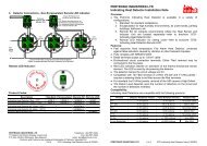
VESDA ®Typical Wiring To Fire Panel (FACP)<strong>LaserFOCUS</strong> <strong>VLF</strong>-<strong>250</strong> <strong>Product</strong> <strong>Guide</strong>The diagram below shows the correct way to wire VESDA laser detectors to a conventional firepanel (FACP). It also shows where an End Of Line (EOL) resistor is correctly installed.To next detectoror EOL resistorDetectorNormally Closed (NC)Common (C)Normally Open (NO)Normally Closed (NC)Common (C)Normally Open (NO)Fire Panel (FACP)InputShort = FireOpen = FaultNormally Closed (NC)Common (C)Normally Open (NO)GPI(Set to reset)EOL(NC)Reset (C)(NO)Figure 12 - Typical wiring to a fire panel with EOLWiring To an Address Loop Module.This wiring example is for wiring VESDA detectors to a typical Address Loop module 3 output 1input. These are example drawings. Refer to the appropriate product manual for the exact wiringdetails of the third party equipment.DetectorNormally Closed (NC)FIRE 1 Common (C)Normally Open (NO)Normally Closed (NC)ACTION Common (C)Normally Open (NO)Normally Closed (NC)FAULT Common (C)Normally Open (NO)EOLEOLEOL3 output 1 input Loop ModuleFire InputShort = FireOpen = FaultPre AlarmShort = FireOpen = FaultFault InputShort= Detector FaultOpen = Wiring FaultGPI(Set to reset)To Next DetectorEOL(NC)Reset (C)(NO)To FACPFigure 13 - Addressable Loop Module with EOL11
<strong>LaserFOCUS</strong> <strong>VLF</strong>-<strong>250</strong> <strong>Product</strong> <strong>Guide</strong> VESDA ®Interface cardThe VESDA <strong>LaserFOCUS</strong> allows for the installation of a variety of interface cards. Refer to thespecific interface card installation sheet, product guide, or your local VESDA support person forfurther information regarding installation and configuration of this card.RS232 Compatible serial portThe RS232 serial port requires a standard 9-pin DB9 PC COM serial extension cable (male tofemale) for configuring the detector using a PC with VESDA System Configurator (VSC)installed, for status monitoring and command input, and for event log extraction and softwareupgrades. For code specific information see page ii.LegendBAB9 Pin DB9 PC COM Serialextension cable (male)Cutaway, exposing theRS232 Serial Port(female)AFigure 14 - 9 Pin connector and RS232 serial port12
VESDA ®Installation Checklist<strong>LaserFOCUS</strong> <strong>VLF</strong>-<strong>250</strong> <strong>Product</strong> <strong>Guide</strong>Site NameAddressDetector Serial Number(s)Name of InstallerSignatureDatePerform the following checks listed below to ensure that all the necessary items are completedbefore handing over to a commissioning engineer.INSTALLATION CHECKS Yes No1. Were the detector and the mounting bracket intact in the box?2. Is the detector securely locked onto its mounting bracket? Notethat the two mounting bracket securing-screws are provided in aseparate bag with the detector.3. Is the sampling air pipe firmly connected to the air inlet port?Ensure the pipe is NOT glued.4. Have the power wires been connected to the correct terminals onthe detector?5. If required, has the end of line resistor been connected?6. Have the alarm signalling wires been terminated to the correctterminals of the detector?7. Have the VESDAnet wires been connected to the correctterminals on the VESDAnet Interface card (if applicable)?8. Has the plug at the exhaust port been removed and the exhaustpipe (if fitted) not glued?9. Has the front cover been replaced correctly?10.Has AutoLearn Flow and AutoLearn Smoke been performed?Please state the AutoLearn Smoke period____________11.Is the air sampling pipework installed and checked as per the siteplans?Table 2 - Installation Checklist1.4 Sampling Pipe Network DesignThe VESDA <strong>LaserFOCUS</strong> supports a number of pre-engineered pipe network designs to simplifyinstallation. The pre-engineered pipe networks have been designed with pressure, flow andtransport time considerations. They have been verified and are shown below. For setup detailsrefer to the VESDA System Design Manual.The pre-engineered designs assume the following constraints:13
<strong>LaserFOCUS</strong> <strong>VLF</strong>-<strong>250</strong> <strong>Product</strong> <strong>Guide</strong> VESDA ®1. There must be no mixing of open hole and capillary tubes in a pipe network design. Allsampling points must be of the same type.2. All sampling points must be evenly spaced in a pipe network design.3. Branched designs must use the same number of sampling points along each branch.4. Open hole designs must use the same size hole throughout the design.5. Capillary tube designs must use the same size and length of capillary tube throughout thedesign.6. The distance from the detector to the first sampling point must be 1 to 2 times the distancebetween sampling points. For example, if the sampling points are 4 meters apart, then thedistance from the detector to the first sampling point must be between 4 and 8 meters.Given the constraints detailed above, the pre-engineered pipe network designs will provide:ParameterTransport timesSuction pressureDetector pressureFlow rateValueless than 60 seconds for open holesless than 90 seconds for capillary tubesgreater than or equal to 25 Pa across holes and capillary tubesgreater than 70 Pa12 - 24 L/minFor alternate or complex pipe network designs including end caps with sampling holes use theASPIRE2 pipe modeling software to verify pipe performance. For code specific information seepage ii.Single pipe networkThe table below shows the appropriate hole sizes for pre-engineered designs for a single pipeset up.Single Pipe Network – max. length 25 m (80 ft.)SamplingholesID 21 mm PipeOpen Hole5.2 mm Capillary*with 5 mm holeIPS ¾ in. PipeOpen Hole3 /8 in. Capillary*with 1 / 8 in. holeHole Size (mm) Length (m) Hole Size (in.) Length (ft.)3 3.5 – 5.0 0 – 0.8 5 /32 – 3 / 16N/A4 3.0 – 4.5 0.2 – 1.1 1 /8 – 5 / 320 – 125 3.0 – 4.0 0.3 – 1.5 1 /8 – 5 / 320 – 126 3.0 – 3.5 0.5 – 1.8 1 /80 – 127-12 Use ASPIRE2 to calculate hole sizes in this range*Table 3 - Single pipe hole numbers and sizes*For code specific information see page ii.14
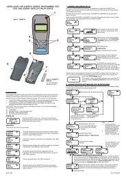
VESDA ®<strong>LaserFOCUS</strong> <strong>VLF</strong>-<strong>250</strong> <strong>Product</strong> <strong>Guide</strong>The set up below shows a single pipe arrangement with 4 sampling holes and a fitted end capwithout a sampling hole.CBALegendA Smoke detector B Sampling hole C End cap (no hole)Figure 15 - Open hole, single pipeThe set up below shows a single pipe arrangement with 6 capillary drop pipes and a fitted endcap without a sampling hole.CBALegendA Smoke detector B Capillary tube C End cap (no hole)Figure 16 - Capillary tubes, single pipe15
<strong>LaserFOCUS</strong> <strong>VLF</strong>-<strong>250</strong> <strong>Product</strong> <strong>Guide</strong> VESDA ®Branched pipe networkThe table below shows the appropriate hole sizes for pre-engineered designs for a branchedpipe set up.Branched Pipe Network –(2 branches)max. length 15 m (50 ft.)max. distance from detector to branch 5 m (15 ft.)SamplingHoles perBranchpipeID 21 mm PipeOpen Hole5.2 mm Capillary*with 5 mm holeIPS ¾ in. PipeOpen Hole3 /8 in. Capillary*with 1 / 8 in. holeHole Size (mm) Length (m) Hole Size (in.) Length (ft.)2 3.0 – 4.5 0.1 – 1.1 1 /8 – 5 / 320 – 123 3.0 – 3.5 0.5 – 1.8 1 /80 – 124 2.5* – 3.0 0.7 – 2.4 1 /80 – 125-6 Use ASPIRE2 to calculate hole sizes in this range*Table 4 - Branched pipe hole numbers and sizes*For code specific information see page ii.The set up below shows a branched pipe arrangement with 5 sampling holes per branch andfitted end caps without sampling holes.CBACLegendA Smoke detector B Sampling hole C End cap (no hole)Figure 17 - Open hole, branched pipe16
VESDA ®<strong>LaserFOCUS</strong> <strong>VLF</strong>-<strong>250</strong> <strong>Product</strong> <strong>Guide</strong>The set up below shows a branched pipe arrangement with 3 capillary drop pipes per branch andfitted end caps without sampling holes.CBACBLegendA Smoke detector B Capillary tube C End cap (no hole)Figure 18 - Capillary pipes, branched pipeReturn air sampling (return grilles)The VESDA <strong>LaserFOCUS</strong> is suitable for air sampling across return air grilles of Air HandlingUnits. The recommended coverage of the VESDA <strong>LaserFOCUS</strong> is 0.4 m 2 (4 sq. ft.) per samplinghole. This should be considered in conjunction with local codes and standard.Note: Rotate the air sampling hole approximately 45 o away from the direction of theincoming airflow and towards the grille surface. This will minimize the risk of aLow Flow Fault being recorded in situations where air flow changes(e.g. where the Air Handling Unit is turned off).Some points to consider for setting up a pipe network are:• sampling holes should be evenly spaced (within 20% of the separation distance to eachother)• an un-vented end cap should be fitted to the end of the sampling pipe• during installation, consideration should be given to the future maintenance requirements ofthe air handling unit. Access to filters should not be restricted and pipe network should beeasily removable by the use of socket unionsFor full details concerning return air grille sampling pipe network design, consult the VESDASystem Design Manual.17
<strong>LaserFOCUS</strong> <strong>VLF</strong>-<strong>250</strong> <strong>Product</strong> <strong>Guide</strong> VESDA ®The table below shows the appropriate hole sizes for pre-engineered designs for return air grilleset ups.Return Air Sampling – U Shaped design with equal holes on each sideSamplingHolesID 21 mm PipeHole Size (mm)IPS ¾ in. PipeHole Size (in.)4 3.0 – 4.0 1 /8 – 5 / 326 3.0 – 3.5 1 /88 3.0 3 /3210 2.5* 3 /32DTable 5 - Return air sampling pipe hole numbers and sizes*For code specific information see page ii.ACBLegendA Sampling pipe C Return grilleB Sampling hole D End cap (no hole)Figure 19 - Return air sampling over an air handling unit grilleInstallation considerationsThe VESDA <strong>LaserFOCUS</strong> <strong>VLF</strong>-<strong>250</strong> smoke detector provides very early warning smokedetection specifically for small environments.The pre-engineered pipe network designs can support up to 6 sampling holes for single pipesand 8 sampling holes for branched pipe arrangements. The number of sampling holes used canbe increased to 12, however, ASPIRE2 will need to verify that the additional sampling holes canbe supported. Sampling holes are positioned according to the standards relating to conventionalpoint detector placement.18
VESDA ®<strong>LaserFOCUS</strong> <strong>VLF</strong>-<strong>250</strong> <strong>Product</strong> <strong>Guide</strong>The pre-engineered pipe network solutions described in sections Single pipe network on page 10and Branched pipe network on page 11 achieved transport times of less than 60 seconds foropen hole sampling and less than 90 seconds for capillary sampling.Where the VESDA <strong>LaserFOCUS</strong> is located outside the protected area (e.g. in a corridor outsidethe room), consideration must be given to returning the detector exhaust air to the protectedenvironment to balance the pressure differences that may exist. In the majority of applications,this is not necessary as pressure differences are minimal.Where practical considerations fall outside pre-engineered designs or where pressuredifferences exceed 50 Pa, in situations where the detector is located outside the protected area,the solutions presented in this manual may not be suitable and it is recommended that alternatedesigns are verified by a suitably qualified installer using ASPIRE2.The following points should be considered when installing the sampling pipe:• minimize flexing in sampling pipes by supporting the pipe every 1.5 m (5 ft) or less, or at adistance described in local codes and standards.• evenly arrange the sampling pipe network over return air grilles• sampling pipes fit firmly into the tapered detector ports, DO NOT glue this connection• allow sufficient movement at the detector to permit pipe removal for maintenance• keep the exhaust deflector fitted to prevent foreign objects falling into the detector• keep the return air pipe as short as possible to minimize airflow resistance in the pipe• pipe ends must be made smooth for bonding• sampling holes must be drilled in line and perpendicular to the pipe.• sample holes must be clear of rough edges and debris• pipes are free of debris• all joints must be bonded except those entering the detectorNote: In protected areas sampling holes should face into the direction of airflow or pointdownwards in static airflow situations.Note: You should try to keep the sampling holes evenly spaced.Note: For code specific information see page ii.Air sampling in a ductFor air sampling in a duct please refer to the VESDA System Design Manual for duct probedesign. For code specific information see page ii.1.5 CommissioningGeneralThe VESDA <strong>LaserFOCUS</strong> has been designed to simplify commissioning processes. TheAutoLearn function allows the unit to assess its environment and setup appropriate alarm andflow thresholds. The unit may also be programmed through VESDA System Configurator (VSC)software, for all programmable settings. For further information see Factory Defaults on page 31.Note: Detectors should be commissioned with a smoke test.Prior to commissioning the detector, check:1. That the power is connected and on.2. That the pipe network is clean and correctly fitted with all joints correctly seated and sealed(except the pipe which enters the detector which must not be glued).3. That the exhaust deflector is fitted.For code specific information see page ii.19
<strong>LaserFOCUS</strong> <strong>VLF</strong>-<strong>250</strong> <strong>Product</strong> <strong>Guide</strong> VESDA ®ABCDLegendABCDAutoLearn Smoke button.AutoLearn Smoke indicatorAutoLearn Flow indicatorAutoLearn Flow ButtonNote:Note:Figure 20 - Interface displayIt is important that the protected area is working under normal operating conditionswhen operating the AutoLearn processes.AutoLearn functions can be de-activated by a second press of the appropriatebutton this will leave the thresholds at their default settings and not at the settingsprior to AutoLearn.AutoLearn SmokeAutoLearn Smoke is initiated by pressing the recessed button numbered 1, which is locatedunder the field service access door.During the AutoLearn Smoke process, the VESDA <strong>LaserFOCUS</strong> determines the average smokeand peak smoke obscuration levels and sets suitable alarm thresholds for the operatingenvironment. This process will minimize false alarms due to normal environment smoke variations.The AutoLearn Smoke LED will remain on for the duration of the AutoLearn process. At the startof the process the alarm thresholds are set to the default values. During this learning cycle, alarmconditions can be reported. If an alarm condition occurs (Alert or higher alarm) AutoLearn will notcomplete its cycle. In this situation restart the AutoLearn process. If AutoLearn is stopped by youor due to an alarm condition, the alarm thresholds will be left at the default settings.Conditions during learning are assumed to be representative of normal operatingconditions.The AutoLearn Smoke learning times range from above 15 minutes to 15 days, with the defaultbeing set to 14 days.20
VESDA ®<strong>LaserFOCUS</strong> <strong>VLF</strong>-<strong>250</strong> <strong>Product</strong> <strong>Guide</strong>If AutoLearn is running during the changeover period from Day and Night Thresholds function,make sure that AutoLearn runs for at least an hour in both the Day and Night.Alarm LevelAlertActionFire 1Fire 2AutoLearn Smoke Range0.025 - 0.4 %obs/m (0.008 - 0.125 %obs/ft)*0.044 - 0.7 %obs/m (0.014 - 0.219 %obs/ft)*0.063 - 1.0 %obs/m (0.020 - 0.313 %obs/ft)*0.313 - 5.0 %obs/m (0.100 - 0.563 %obs/ft)*Table 6 - AutoLearn Smoke range*For code specific information see page ii.AutoLearn FlowAutoLearn Flow process is initiated by pressing the recessed button numbered 2, which islocated under the field service access door. During the AutoLearn Flow process, the VESDA<strong>LaserFOCUS</strong> determines the average and peak air flow levels monitored over time and setssuitable alarm thresholds that will not give rise to false flow rates due to normal flow variations(such as might arise through air-conditioning related false alarms). The system will normalize theflow and then monitor the flow trend to set the flow fail thresholds.The AutoLearn Flow indicator LED will remain on for the duration of the AutoLearn process. Atthe start of the process the flow thresholds are set to the default values. During this learningcycle, alarm conditions can be reported. If a flow fault is reached, AutoLearn will not complete itscycle. In this situation restart the AutoLearn process. If AutoLearn is stopped by you or due to aflow fault condition, the flow thresholds will be left at the default settings.Conditions during learning are assumed to be representative of normal operatingconditions.The AutoLearn Flow learning times range from 15 minutes to 15 days, with the default being setto 14 days.VESDA System Configurator (VSC)The VESDA System Configurator is an optional tool that allows all VESDA detectors to beconfigured. All parameters can be set manually or previously saved configuration settings maybe applied. Refer to the VSC documentation for details regarding the setting of these thresholds.Commissioning smoke testIt is recommended that a smoke test be carried out to prove the integrity of the pipe network, todemonstrate that the system is working and to measure the transport time to the detector.This test involves introducing a smoke sample at the furthest sampling hole and then measuringthe time taken for the smoke to travel to the detector. Results are logged and compared tosubsequent tests to note variations of the system.See the VESDA System Design Manual for details of the commissioning smoke test.21
<strong>LaserFOCUS</strong> <strong>VLF</strong>-<strong>250</strong> <strong>Product</strong> <strong>Guide</strong> VESDA ®1.6 Detector OverviewFeatures• Laser Based Absolute Smoke Detection• Wide Sensitivity Range• Programmable Alarm Thresholds• Dual Stage Air Filtration• Instant Recognition Display• Instant Fault Finder TM• AutoLearn TM Smoke• AutoLearn TM Flow• Ultrasonic Flow Sensing• Referencing (requires a VESDAnet Interface Card)• Field Service Access Door• Separate Event Logging• Pipe Modeling Support Software – ASPIRE2 TM• VESDA System Configurator (VSC) for field supportDescriptionThe Instant Recognition Display of the VESDA <strong>LaserFOCUS</strong> smoke detector shows alarm levelsand detector status information. The Smoke Dial, (see (F) in figure 21, “<strong>LaserFOCUS</strong> detectorfront view,” on page 23, a part of the Instant Recognition Display, provides clear information of asmoke event, relative to the Fire 1 Alarm Threshold. This display also identifies system andoperational faults, when using the Instant Fault Finder function. Each segment of the Smoke Dialalso corresponds to a specific fault condition.A Field Service Access Door is provided to allow easy access to AutoLearn functions for detectorcommissioning. It provides access for filter replacement and connecting a PC for comprehensiveconfiguration and diagnostics processes.The detector uses Ultrasonic Flow Sensing to monitor the integrity of the sampling pipe networkby detecting pipe air flow change. Ultrasonic flow sensing is not affected by temperature,humidity or pressure.Detector history is provided by the non-volatile Event Logging feature. Smoke trend data, flowtrend data, fault events, configuration events and operational events are recorded. Using VSCthese event types can be filtered individually.ApplicationsThe VESDA <strong>LaserFOCUS</strong> can be used for open areas, return air grilles, or for cabinet protectionin many small areas including:• telecommunication facilities• computer rooms• control rooms• storage facilities• electrical and switching cabinetsFor code specific information see page ii.22
VESDA ®1.7 <strong>Product</strong> Interface<strong>LaserFOCUS</strong> <strong>VLF</strong>-<strong>250</strong> <strong>Product</strong> <strong>Guide</strong>The VESDA <strong>LaserFOCUS</strong> provides the following information and control options without theneed for additional configuration tools.• Detector status: Normal, Alarm, Disabled and Fault.• Alarm levels: Alert, Action, Fire 1 and Fire 2.• Smoke levels relative to Fire 1.• Detector fault types (Instant Fault Finder).• Test, Reset and Disable.• AutoLearn Smoke (setting alarm thresholds).• AutoLearn Flow (setting baseline for normal air flow and flow thresholds).Front viewFront view of the detector as installed and operating. This view shows cable and air samplingpipe entry points, the Instant Recognition display and the fitted exhaust deflector.BCADEFLegendA Air inlet port D Rear cable entry (not shown)B Exhaust deflector E Instant Recognition DisplayC Cable entry ports (x2) F Smoke Dial (includes Instant Fault Finder)Figure 21 - <strong>LaserFOCUS</strong> detector front view23
<strong>LaserFOCUS</strong> <strong>VLF</strong>-<strong>250</strong> <strong>Product</strong> <strong>Guide</strong> VESDA ®Instant Recognition DisplayThe Instant Recognition display provides you with an immediate understanding of smoke levelsrelative to Fire 1 alarm threshold.ACGBDEFLegendOption Definition LED ColorA FIRE 2 Indicates the Fire 2 threshold has been reached. RedB FIRE 1 Indicates the Fire 1 threshold has been reached. RedC ACTION Indicates the Action condition has been reached. RedD ALERT Indicates the Alert condition has been reached. RedE DISABLED Indicates the unit has been disabled (solid) or is in standby mode (flashing). YellowF POWER Illuminates when the detector is powered. GreenG FAULT Fault light continuously on indicates an Urgent Fault (UF). When flashingindicates a non-urgent fault (NUF).YellowNote:Figure 22 - Instant Recognition DisplayThere are two sets of Instant Recognition display icons; both are shown throughoutthis manual. The international icon set can be identified by the lack of English textbeside the icons.24
VESDA ®Controls and indicators<strong>LaserFOCUS</strong> <strong>VLF</strong>-<strong>250</strong> <strong>Product</strong> <strong>Guide</strong>Control buttons are accessed by opening the field service access door. This door is opened bypressing in the security tab, on the right side of the detector, with a flat screw driver and thenlifting the door by the finger clips on each side of the door (see Figure 3, “Field Service AccessDoor security tab and clip,” on page 4).ACLegendASecurity tabBCFinger clipField service access doorBFigure 23 - Field Service Access Door security tab and clip25
<strong>LaserFOCUS</strong> <strong>VLF</strong>-<strong>250</strong> <strong>Product</strong> <strong>Guide</strong> VESDA ®Interface information and control buttonsInterface information and control buttons are located behind the field service access door.ABCDEFGHLegendABCDEFGHInstant Fault Finder fault descriptions.Dual stage air filter cartridge.Alarm level definitions.Control buttons - Reset, Disable, (Instant Fault Finder) & Test.RS232 DB9F serial port.Control buttons - AutoLearn Smoke, AutoLearn Flow.Control button definitions.Security tab.Figure 24 - <strong>LaserFOCUS</strong> detector with field service access door open26
VESDA ®Detector control buttons<strong>LaserFOCUS</strong> <strong>VLF</strong>-<strong>250</strong> <strong>Product</strong> <strong>Guide</strong>Icon Button Use DescriptionResetDisableInstant FaultFinderResets thesystem andresumes normaloperation.Disables the firerelay outputsfrom actuatingand reports afault.Pressing Disablefor 6 seconds willput the detectorinto Stand-bymode.Indicates currentactive faults onthe detector.Press and hold down this button to testthe function of LEDs on the unit.To enable or lockout this button VESDASystem Configurator (VSC) software isrequired.Release this button to clear latched faultsand alarms. Alarm and fault lights willswitch off, and if the system is still inalarm or fault mode, the lights willreappear after the appropriate delay.This button allows the operator to togglebetween disable and normal modes.When disabled smoke and air flow are notreported to the system (e.g. FACP).To enable or lockout this button VESDASystem Configurator (VSC) software isrequired.The fan contines to run when <strong>VLF</strong> isdisabled but stops when it is in stand-bymode.Pressing and holding in the Reset buttonand the Disable button together will showthe fault type, by number, on the SmokeDial.See “<strong>VLF</strong> Troubleshooting with InstantFault Finder” on page 30. for the faultdefinitions.Fire 1 TestSimulates aFire 1 conditionand the alarmrelay is activatedafter theappropriate delayNote: This willinitiate a Fire 1Alarm.By default this button is locked out. Toactivate this button VESDA SystemConfigurator (VSC) software is required.Note: Notify the monitoring authoritybefore testing commences.To activate, press and release the Fire 1Test button. All the segments of theSmoke Dial, and alarm conditions up toFire 1 are activated (after the configureddelay period). Press the Reset button tostop the test and clear any latchedalarms.Note: Remember to return the system tonormal mode after the test is complete.27
<strong>LaserFOCUS</strong> <strong>VLF</strong>-<strong>250</strong> <strong>Product</strong> <strong>Guide</strong> VESDA ®AutoLearnSmokeAutoLearnFlowAutomaticallysets alarmthreshold valuesbased on thenormal operatingenvironment.See “AutoLearnSmoke” onpage 20.The detectorautomaticallymeasures air flowto the pipes andsets the air flowthreshold values.See “AutoLearnFlow” onpage 21.Pressing the recessed AutoLearn Smokebutton initiates the automatic smokealarm set-up mode. The LED, beside thebutton, will remain on for the duration ofthe AutoLearn process (up to 14 dayswhich is also the default period). Duringthis period the unit is online, alarms arecommunicated and default thresholds areactive. To deactivate this function, pressthe AutoLearn Smoke button again.Pressing the recessed AutoLearn Flowbutton sets the airflow fault thresholds aswell as normalizing the detector’s airflow.The LED, beside the button, will remainon for the duration of the AutoLearnprocess (up to 14 days which is also thedefault period). To deactivate thisfunction, press the AutoLearn Flow buttonagain.Table 7 - Detector ButtonsSmoke level & Instant Fault Finder displaysUnder normal operating conditions the circular Smoke Dial displays smoke levels in sampled air.Through Instant Fault Finder, the Smoke Dial temporarily changes the segments into faultindicators, with each segment corresponding to a specific fault condition.28
VESDA ®Smoke level display<strong>LaserFOCUS</strong> <strong>VLF</strong>-<strong>250</strong> <strong>Product</strong> <strong>Guide</strong>The smoke level is displayed on the Smoke Dial (A) and provides incident information essentialfor effective response in very early warning situations. This display provides you with an instantunderstanding of the smoke event relative to the Fire 1 Alarm Threshold. Between 1 and 10segments may illuminate. Each segment is equivalent to 1 / 10 of a Fire 1 warning.BCDALegendA Smoke Dial and Fault Type indicator. C Disable button.B Reset button. D Fault light.Instant Fault FinderFigure 25 - Smoke level and fault condition displayWhen a fault is registered on the detector, the fault light (D) remains on for Urgent Fault (UF)situations and flashes for Non-Urgent Faults (NUF).The Instant Fault Finder function is operated by pressing the Reset and Disable buttons together.Instant Fault Finder provides rapid fault diagnosis and is an additional function of the Smoke Dialdisplay. One or more segments of the Smoke Dial will illuminate, indicating the fault by number.The table below provides fault details and recommended actions.29
<strong>LaserFOCUS</strong> <strong>VLF</strong>-<strong>250</strong> <strong>Product</strong> <strong>Guide</strong> VESDA ®<strong>VLF</strong> Troubleshooting with Instant Fault FinderThe Instant Fault Finder function aids rapid diagnosis of faults.Fault Type Explanation Action1 Filter Air filter needs replacementdue to dust or smokecontamination or has reachedthe end of its life.Replace the air filter with a newunit remembering to reset the filterfault.2 Aspirator Aspirator fault has occurred. Initially replace the aspirator. If thefault remains replace the VESDAunit.3 High flow High flow fault present (urgentor non-urgent). Flow readingsare above user set flow limitsor the detector maximum flow4 Low flow Low flow fault present (urgentor non-urgent). Flow readingsare below user set flow limitsor the detector maximum flowCheck the pipe network forbreakages. Also check thesuitability of the pipe network inASPIRE2.Check the pipe network forbreakages. Also check thesuitability of the pipe network inASPIRE2.5 Not in use6 ExternalDevice/PowerSupply Unit7 Interface card(available at alater date)External equipment signaling afault via the General PurposeInput.Interface Card needsreplacement.Inspect the external device andalso check that the GPI is set tothe correct mode.Also check that the EOL resistor iscorrectly connected.Replace the Interface Card.8 Field wiring General Purpose Input orInterface Card wiring.9 AutoLearn fail AutoLearn Smoke or Flowfailed.If no interface card is installedcheck the GPI wiring for an opencircuit.If an interface card is installed referto the card manual.Refer to GPI section of the<strong>LaserFOCUS</strong> ManualRepeat AutoLearn Smoke or Flowprocess. Inspect logs if repeatedfailures occur.10 DetectorfailureA fault has occurred thatcannot be fixed.Contact the supplier and replacethe detector.Table 8 - Instant fault finder diagnosis30
VESDA ®1.8 Factory Defaults<strong>LaserFOCUS</strong> <strong>VLF</strong>-<strong>250</strong> <strong>Product</strong> <strong>Guide</strong>Parameter Allowed values Default valuesAlert Smoke Threshold 1 & 2Action Smoke Threshold 1 & 2Fire-1 Smoke Threshold 1 & 2Fire-2 Smoke Threshold 1 & 20.025% - 2.0% obs/m*(0.008% - 0.625% obs/ft.)0.025% - 2.0% obs/m*(0.008% - 0.625% obs/ft.)0.025% - 20% obs/m*(0.008% - 6.25% obs/ft.)0.025% - 20% obs/m*(0.008% - 6.25% obs/ft.)0.08% obs/m(0.025% obs/ft.)0.14% obs/m(0.0448% obs/ft.)0.2% obs/m(0.0625% obs/ft.)2.0% obs/m(0.625% obs/ft.)Alert Verification Delay 1 & 2 0 - 60 seconds 10 secondsAction Verification Delay 1 & 2 0 - 60 seconds 10 secondsFire 1 Verification Delay 1 & 2 0 - 60 seconds 10 secondsFire 2 Verification Delay 1 & 2 0 - 60 seconds 10 secondsAlarm Latching Enable Enabled or Disabled EnabledFault Latching Enable Enabled or Disabled DisabledAirflow – Urgent High Flow Fault 100% - 150% 130%Airflow – Urgent Low Flow Fault 50% - 100% 70%Airflow – Non-Urgent High Flow Fault 100% - 150% 120%Airflow – Non-Urgent Low Flow Fault 50% to 100% 80%AutoLearn Smoke 15 min. – 15 days 14 daysAutoLearn Flow 15 min. – 15 days 14 daysSmoke Test Button Enable/Disable DisabledThreshold set 1 and 2 Day (1) & Night (2) /DisabledDisabledTable 9 - Factory defaults*For code specific information see page ii.31
<strong>LaserFOCUS</strong> <strong>VLF</strong>-<strong>250</strong> <strong>Product</strong> <strong>Guide</strong> VESDA ®1.9 SpecificationsPower SupplySupply VoltagePower Consumption @ 24 VDCCurrent Consumption @ 24 VDC24 VDC nominal (18 - 30 VDC)*5.2 W nominal, 7.0 W in alarm*220 mA nominal, 295 mA in alarm**For code specific information see page ii.CaseDimensions (WHD)245 mm x 175 mm x 90 mm(9 5 / 8 in. x 6 7 / 8 in. x 3 1 / 2 in.)WeightIP RatingMountingMaintenance access2 kg (approx. 4.4 lbs)IP30Upright, inverted or horizontal with appropriatemounting bracketInstant Fault Finder, Filter and Programming PortOperating ConditionsDetector AmbientSampled Air0 o C to 40 o C (32 o F to 104 o F)0 o C to 40 o C (32 o F to 104 o F)Humidity (non-condensing) 5% to 95 %Sampling NetworkAir inlet pipeSingle pipe lengthSingle pipe - Sampling holesBranch (2) pipe lengthBranch (2) - Sampling holesReturn Air Sampling – U ShapeddesignOD 25 mm (ID 21 mm) / IPS ¾ in. (OD 1.05 in.)Alternate pipe sizes can be modelled with ASPIRE225 m (80 ft.) max.3-6 sampling holes pre-engineeredFor 7-12sampling holes model with ASPIRE215 m (50 ft.) max. per branch2-4 sampling holes pre-engineeredFor sampling holes model with ASPIRE24-10 sampling holes pre-engineered32
VESDA ®<strong>LaserFOCUS</strong> <strong>VLF</strong>-<strong>250</strong> <strong>Product</strong> <strong>Guide</strong>Area Covered<strong>250</strong> m 2 (<strong>250</strong>0 sq. ft.)Field WiringAccessTerminals3 x 25 mm (1 in.) Cable entries (1 rear entry)0.2 mm 2 - 2.5 mm 2 (30 - 12 AWG)InterfacesPower In/Out.Fire 1 Relay (changeover, 2A @ 30 VDC).Action Relay (changeover, 2A @ 30 VDC).Fault Relay (changeover, 2A @ 30 VDC).General Purpose Input (clean contact).External display port (with power limited output).RS232 programming port.Alarm RangesAlert, ActionFire 1, Fire 2Individual Delays0.025 – 2.0% obs/m (0.008 – 0.625% obs/ft.)*0.025 – 20% obs/m (0.008 – 6.25% obs/ft.)*0 - 60 seconds2 Threshold sets (1 & 2) Day and nightFor code specific information see page ii.Display4 Alarm State Indicators.Fault and Disabled Indicators.Smoke Level Indicators.Instant Fault Finder.Reset, Disable and Test Controls.Smoke and Flow AutoLearn Controls and Indicators.33
<strong>LaserFOCUS</strong> <strong>VLF</strong>-<strong>250</strong> <strong>Product</strong> <strong>Guide</strong> VESDA ®Event LogUp to 18 000 events stored.Smoke trend, flow trend, faults events, configuration events and operational events.Date and time stamp.AutoLearn Smoke & FlowMinimum 15 minutes, maximum 15 days (default 14 days).During AutoLearn, thresholds are NOT changed from pre-set values.ReferencingReference smoke level source for networked detectors (requires a VESDAnet Interfacecard).Ordering InformationVESDA <strong>LaserFOCUS</strong> <strong>VLF</strong>-<strong>250</strong>Filter CartridgeAspiratorVESDAnet Interface Card<strong>VLF</strong>-<strong>250</strong>-00, <strong>VLF</strong>-<strong>250</strong>-01, <strong>VLF</strong>-<strong>250</strong>-02VSP-005VSP-715VIC-0101.10 MaintenanceOverviewThe VESDA <strong>LaserFOCUS</strong> smoke detector continuously monitors its own operation and conductsfrequent health checks. There are two serviceable items, the air filter cartridge and the aspirator.Caution:Electrostatic discharge precautions need to be taken prior to removing the frontcover from the detector otherwise damage may occur to the detector.34
VESDA ®<strong>LaserFOCUS</strong> <strong>VLF</strong>-<strong>250</strong> <strong>Product</strong> <strong>Guide</strong>ALegendABDual stage air filtercartridgeAspiratorBMaintenance scheduleFigure 26 - Maintenance - replaceable itemsTo maintain the VESDA <strong>LaserFOCUS</strong> smoke detector in peak working order follow themaintenance standards for your region and where no recommended standard exists see thetable below. Please note, for environments that experience high levels of contamination, thefrequency of maintenance will need to be increased. Maintenance should be conducted by aqualified service contractor.Action Frequency DetailsCheck pipenetwork6 monthly Check pipe connections to ensure all pipe runs areintact and that pipe supports and joints are firm.Airflow Yearly Check air flow via VSC software (refer to the VESDASystem Configurator Manual). Compare the currentreading with previous reading to determine if the flowrate has reduced.Smoke test Yearly Conduct smoke tests and verify detector performance(refer to the System Design Manual).Compare response times with those previouslyrecorded and investigate any discrepancies.CheckpowersuppliesYearlyTest in accordance with suppliers instructionsFilterreplacement2 Yearly Recommended change out period. The filter status canbe checked via VSC software. Depending on theenvironment, the filter may require more frequentchecking.CleansamplingholesAs necessaryIf frequent low flow faults occur clean the sampling pipenetwork by back flushing (refer to the System DesignManual).Table 10 - Maintenance schedule35
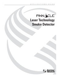
<strong>LaserFOCUS</strong> <strong>VLF</strong>-<strong>250</strong> <strong>Product</strong> <strong>Guide</strong> VESDA ®Filter replacementThe VESDA <strong>LaserFOCUS</strong> smoke detector uses a disposable dual stage air filter cartridge. Thisfilter removes dust contamination from sampled air and provides a clean air bleed to preserve thedetector chamber optics. The detector constantly monitors filter efficiency. To maintain theoperational integrity of the smoke detector, it is recommended that the filter be replaced every2 years, or when a filter fault occurs or more often for environments that experience high levels ofcontamination.A fault is raised on the detector, when the filter needs to be replaced. During the replacementprocess the detector needs to be informed that a new filter has been installed.Note:Note:Note:Prior to any work or maintenance being carried out on the VESDA <strong>LaserFOCUS</strong>take the necessary steps to advise the monitoring authority that power may beremoved and the system disabled.Ensure the area surrounding the filter is clear of dirt and debris prior to replacement.The filter is for single use only, it cannot be cleaned and re-used.Filter replacement stepsEnsure the detector remains powered up during filter replacement and a new filter cartridge isavailable:1. Push in the security tab and lift up the field service access door (A).2. Set the detector to ‘Standby’ mode by pressing the Disable button for 6 seconds. TheDisabled LED begins to flash. After releasing the Disable button the disabled LED willslowly flash.3. Undo the recessed retaining screw (C) and pull out the old filter (B).4. Using your finger, firmly press the filter switch (D) (in the filter recess of the detector) 5 timeswithin 5 seconds to confirm to the detector that a new filter is about to be installed (seeinset). A LED next to the serial interface will flash each time you push the filter switch, andwill continue flashing once you have successfully pressed the switch 5 times in 5 seconds.5. Insert the new filter (VSP-005) and tighten the retaining screw.6. Press the Disable button for 6 seconds to return the detector to normal operation.7. Record the filter replacement date on the filter.8. Close the field service access door.CALegendAField service access doorDBCDDual stage air filter cartridgeRetaining screwFilter switchBFigure 27 - Filter replacement36
VESDA ®Aspirator replacementNote:<strong>LaserFOCUS</strong> <strong>VLF</strong>-<strong>250</strong> <strong>Product</strong> <strong>Guide</strong>Prior to replacing the aspirator advise the monitoring authority that power will beremoved and the system disabled.Caution:Electrostatic discharge precautions need to be taken prior to removing the frontcover from the detector otherwise damage may occur to the unit.Aspirator removal (assumes normal mounting, see Figure 28):1. Disconnect power to the detector.2. Push in the security tab and lift up the field service access door.3. Unscrew the two front cover retaining screws, lift and swing down the front cover.4. Only disconnect the fan wiring loom from the connection point (E) at the aspirator.5. Undo the retaining screw on the aspirator (A).6. Swing out the aspirator, then lift and remove it from the detector.Note:Note:Any time the aspirator is removed ensure the area surrounding the aspirator is clearof dirt and debris prior to replacement.Care must be taken during aspirator replacement. The aspirator must be correctlyseated; this is essential so that gaskets are not damaged or dislodged from theunderside of the aspirator.Aspirator replacement steps1. Clip the aspirator (VSP-715) into the retaining clip (D) and swing it back into the detector.2. Tighten the retaining screw (A) (do not over tighten).3. Reconnect the fan loom to the aspirator (E).4. Replace the front cover and screw it into place.5. Close the field service access door.6. Reconnect power to the detector.LegendAAspirator securing screwBABCDSwing aspirator out to removeAspiratorRetaining clip pointsCEFan loom connector must bedisconnected hereDEFigure 28 - Aspirator replacement37
<strong>LaserFOCUS</strong> <strong>VLF</strong>-<strong>250</strong> <strong>Product</strong> <strong>Guide</strong> VESDA ®GlossaryA Aspirator Impeller type fan used to draw sampled air into thedetector.C Capillary Tubes Flexible tubes attached to the sampling pipe network forsampling specific areas or objects away from thesampling pipe.D Disable Disables the fire relay outputs from actuating(previously known as Isolate) and indicates a fault.Dual Stage Air FilterCartridgeA disposable air filter cartridge used in VESDA<strong>LaserFOCUS</strong> detectors that removes dustcontamination from sampled air and provides a clean airbleed to maintain the Laser chamber optics.E Event Log All VESDA detectors provide internal data logging ofevents which have occurred in the VESDA protectedzone.F FCC Compliance Federal Communications Commission.GHFire 1Fire Alarm ControlPanel (FACP)General Purpose Input(GPI)High AirflowEnvironmentThis indicates a serious situation and may lead toautomatic generation of a normal fire alarm.A panel which all fire detection products report theirstatus to.The General Purpose Input is a programmable input.Where there are 10 or more air exchanges per hour.I Instant Fault Finder Illuminates one or more segments of the Smoke Dialwith corresponding fault numbers.L <strong>LaserFOCUS</strong> An air sampling smoke detector using light scattering toreport smoke obscuration.O Obscuration The reduction in light passing through a uniform lengthdue to the presence of particulates.R Relay The connection on a VESDA detector which allowsexternal equipment to be hard wired to it and betriggered when various conditions occur (example,sounding a siren at Alert threshold).S Sampling Network The pipe network constructed to allow the VESDAdetector to draw air for sampling.SensitivityRelative degree of response (i.e. activation of alarmcondition) of a detector. A high sensitivity denotesresponse to a lower concentration of smoke than a lowsensitivity, under identical smoke build-up conditions.V VESDA Brand name for the range of smoke detectors.VSCVESDA System Configurator, a PC based program tool.38
VESDA ®<strong>LaserFOCUS</strong> <strong>VLF</strong>-<strong>250</strong> <strong>Product</strong> <strong>Guide</strong>39
VESDA ®<strong>LaserFOCUS</strong> <strong>VLF</strong>-<strong>250</strong> <strong>Product</strong> <strong>Guide</strong>IndexAApplications........................................ 22Area protected ...................................... 1Aspirator replacement.......................... 37AutoLearn Flow ................................... 21AutoLearn Smoke ................................ 20CClearances............................................ 2Commissioning ................................... 19AutoLearn flow ................................ 21AutoLearn smoke............................. 20Smoke test ..................................... 21Control buttons ................................... 27Conventions .......................................... iiDDefault settings ................................... 31Detector removal ................................... 4FFeatures ............................................. 22Field service access door ..................... 25Filter replacement................................ 36GGlossary............................................. 38IInstant fault finder ............................... 29Troubleshooting guide....................... 30Instant recognition display ................... 24Inverted mounting ................................. 4MMaintenance ....................................... 34Aspirator replacement....................... 37Filter replacement ............................ 36Schedule........................................ 35Mounting .............................................. 1Clearances ....................................... 2Orientation........................................ 1Surface............................................ 2Mounting surface................................... 2PPipe connectionsAir inlet ............................................ 5Exhaust ........................................... 6Pipe network....................................... 13Branched pipe................................. 16Duct .............................................. 19Installation considerations.................. 18Return air ....................................... 17Single pipe ..................................... 14SSerial port........................................... 12Smoke dial.......................................... 29Smoke level ........................................ 29Smoke test.......................................... 21Specifications ..................................... 32Installation........................................ 1, 340
<strong>LaserFOCUS</strong> <strong>VLF</strong>-<strong>250</strong> <strong>Product</strong> <strong>Guide</strong> VESDA ®UUser interface...................................... 23VVESDA System Configurator................. 21WWiring .................................................. 6General Purpose Input ........................ 7Power supply .................................... 9Relays ........................................... 10Spare terminals ................................. 941