D4120 Duct Smoke Detector D4S Sensor ... - Fire-Lite Alarms
D4120 Duct Smoke Detector D4S Sensor ... - Fire-Lite Alarms
D4120 Duct Smoke Detector D4S Sensor ... - Fire-Lite Alarms

Create successful ePaper yourself
Turn your PDF publications into a flip-book with our unique Google optimized e-Paper software.
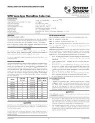
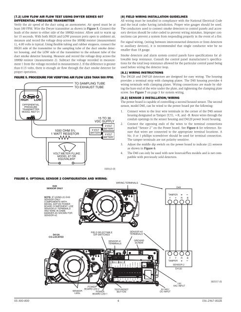
[7.2] Low Flow Air Flow Test using Dwyer Series 607<br />
Differential Pressure Transmitter<br />
Verify the air speed of the duct using an anemometer. Air speed must be at<br />
least 100 FPM. Wire the Dwyer transmitter as shown in Figure 5. Connect the<br />
leads of the meter to either side of the 1000Ω resistor. Allow unit to warm up<br />
for 15 seconds. With both HIGH and LOW pressure ports open to ambient air,<br />
measure and record the voltage drop across the 1000Ω resistor (measurement<br />
1), 4.00 volts is typical. Using flexible tubing and rubber stoppers, connect the<br />
HIGH side of the transmitter to the sampling tube of the duct smoke detector<br />
housing, and the LOW side of the transmitter to the exhaust tube of the<br />
duct smoke detector housing. Measure and record the voltage drop across the<br />
1000Ω resistor (measurement 2). Subtract the voltage recorded in measurement<br />
1 from the voltage recorded in measurement 2. If the difference is greater<br />
than 0.15 volts, there is enough air flow through the duct smoke detector for<br />
proper operation.<br />
Figure 5. Procedure for verifying air flow less than 500 FPM:<br />
HIGH<br />
LOW<br />
DIFFERENTIAL<br />
PRESSURE<br />
TRANSMITTER<br />
MODEL #607-01<br />
1000 OHM 5%<br />
1 WATT RESISTOR<br />
VOLT METER FLUKE<br />
MODEL 87 OR<br />
EQUIVALENT<br />
+ –<br />
TO SAMPLING TUBE<br />
TO EXHAUST TUBE<br />
15 TO 36<br />
VDC SUPPLY<br />
9 VOLT<br />
BATTERY<br />
9 VOLT<br />
BATTERY<br />
9 VOLT<br />
BATTERY<br />
[8] field wiring installation Guidelines<br />
All wiring must be installed in compliance with the National Electrical Code<br />
and the local codes having jurisdiction. Proper wire gauges should be used.<br />
The conductors used to connect smoke detectors to control panels and accessory<br />
devices should be color-coded to prevent wiring mistakes. Improper connections<br />
can prevent a system from responding properly in the event of a fire.<br />
For signal wiring, (wiring between interconnected detectors or from detectors<br />
to auxiliary devices), it is recommended that single conductor wire be no<br />
smaller than 18 gauge.<br />
<strong>Smoke</strong> detectors and alarm system control panels have specifications for allowable<br />
loop resistance. Consult the control panel manufacturer’s specifications<br />
for the total loop resistance allowed for the particular control panel being<br />
used before wiring the detector loop.<br />
[8.1] Wiring Instructions<br />
The <strong>D4120</strong> and D4P120 detectors are designed for easy wiring. The housing<br />
provides a terminal strip with clamping plates. The <strong>D4S</strong> housing provides 4<br />
wiring terminals with clamping plates. Wiring connections are made by sliding<br />
the bare end of the wire under the plate, and tightening the clamping plate<br />
screw. See Figure 7 on page 5 for system wiring.<br />
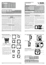
[8.2] <strong>Sensor</strong> 2 Installation/Wiring<br />
The power board is capable of controlling a second housed sensor. The second<br />
sensor, model <strong>D4S</strong>, can be wired to the power board per the following:<br />
1. Connect wires to the four wire terminals in the corner of the <strong>D4S</strong> sensor<br />
housing designated as Tamper (Y,Y), +R, and –B. Route wires through the<br />
conduit openings in the sensor housing and <strong>D4120</strong> power board housing.<br />
2. Connect the opposing ends of the wires to the terminal connections<br />
marked “<strong>Sensor</strong> 2” on the Power board. See Figure 6 for reference. Ensure<br />
that wires are connected to the appropriate terminal locations. A<br />
No. 0 or 1 phillips screwdriver should be used for terminal connection.<br />
The tamper terminals are not polarity sensitive.<br />
3. Adjust the middle dip switch on the power board to indicate (2) sensors<br />
as shown in Figure 6.<br />
4. The <strong>D4S</strong> can only be used with new InnovairFlex models and is not compatible<br />
with previously sold detectors.<br />
H0163-01<br />
Figure 6. Optional sensor 2 configuration and wiring:<br />
<strong>D4S</strong><br />
SENSOR ONLY<br />
NOTE: IF USING (2) <strong>D4S</strong><br />
SENSOR ONLY<br />
COMPONENTS WITH<br />
MODEL D4P120 POWER<br />
BOARD COMPONENT, USE<br />
SENSOR #1 TERMINALS<br />
AND WIRE IN SAME<br />
MANNER AS SHOWN FOR<br />
SENSOR #2.<br />
WIRING TERMINALS<br />
<strong>D4S</strong><br />
TAMPER + –<br />
Y Y R B<br />
<strong>D4120</strong><br />
CO-LOCATED<br />
FIELD SELECTABLE<br />
DIP SWITCHES<br />
SENSOR #1<br />
TERMINALS<br />
SENSOR #2<br />
TERMINALS<br />
GROUND<br />
SCREW<br />
OFF/ON TRBL SHUTDN<br />
1/2 SENSORS<br />
7/0 MIN TMPR DELAY<br />
Y Y R Ḇ Y Y R<br />
TAMPER + TAMPER +<br />
SENSOR 1 SENSOR 2<br />
ACC -<br />
ACC +<br />
R RESET, 2<br />
R TEST, 11<br />
Ḇ<br />
ALARM, 15<br />
INT+, 12<br />
INT/AUX-, 1<br />
AUX OUT -, 20<br />
AUX OUT +, 19<br />
24V AC/DC, 9<br />
24V AC/DC, 10<br />
120 VAC<br />
Y Y R B<br />
TAMPER + –<br />
SENSOR 2<br />
<strong>D4120</strong><br />
SENSOR<br />
LEDs<br />
POWER<br />
BOARD LED 2<br />
POWER<br />
BOARD LED 1<br />
4, C<br />
5, NO<br />
ALARM<br />
13, NC<br />
3, C<br />
SUP<br />
14, N0<br />
16, NC<br />
TEST/RESET<br />
BUTTON<br />
6, C<br />
AUX A<br />
17, NO<br />
8, NC<br />
18, C<br />
AUX B<br />
7, NO<br />
120<br />
VAC INPUT<br />
24 VAC/<br />
DC INPUT<br />
H0557-01<br />
SS-300-000 4 I56-2967-002R