PDF catalog - Who-sells-it.com
PDF catalog - Who-sells-it.com
PDF catalog - Who-sells-it.com

You also want an ePaper? Increase the reach of your titles
YUMPU automatically turns print PDFs into web optimized ePapers that Google loves.
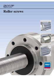
Transmissions<br />
Index<br />
Catalogue Selection INDEX<br />
Enquiry<br />
CD Contents<br />
Cross & Morse Chain Drive Products 2-3<br />
American Standard:<br />
- ANSI Chains 18-19<br />
- Attachment Chains 20-21<br />
- Double P<strong>it</strong>ch Chains 23-25<br />
- Maintenance-Free Chains 22<br />
- Stainless Steel Chains 21<br />
Br<strong>it</strong>ish Standard:<br />
- Attachment Chains 16-17<br />
- Chains ISO 606 14<br />
- Double P<strong>it</strong>ch Chains 15<br />
- Spl Construction Chains 15<br />
- Stainless Steel Chains 15<br />
Centre Distance Calculations 9<br />
Chain Drive Ratios 8<br />
Chain Tensioners 66-70<br />
Drive Design Data 79<br />
Idler Sprockets 65<br />
Inverted Tooth Chain:<br />
- Conveyor Chains 85-88<br />
- Design & Selection 72-73<br />
- Installation 78<br />
- Serpentine Chains 84<br />
- Type HV 71-78<br />
- Type SC 79-83<br />
Keyway Dimensions 80<br />
‘O’ Ring Chains 22<br />
Platewheels:<br />
- 8mm p<strong>it</strong>ch (05B) 54<br />
- 3 /8” p<strong>it</strong>ch (06B) 55<br />
- 1 /2” narrow 56<br />
- 1 /” p<strong>it</strong>ch (08B) 57<br />
- 5 /8” p<strong>it</strong>ch (10B) 58<br />
- 3 /4” p<strong>it</strong>ch (12B) 59<br />
- 1” p<strong>it</strong>ch (16B) 60<br />
- 1 1 /4” p<strong>it</strong>ch (20B) 61<br />
- 1 1 /2” p<strong>it</strong>ch (24B) 62<br />
- 1 3 /4” p<strong>it</strong>ch (28B) 63<br />
- 2” p<strong>it</strong>ch (32B) 63<br />
Platewheel Adaptor Hubs 64-65<br />
Rivet Extractors 33<br />
Roller Chain - Cross+Morse Specification: 4<br />
- Drive Design 5-6<br />
- Drive Selection 7-9<br />
- Installation 13<br />
- Lubrication 12<br />
- Selection Graphs 10-11<br />
Roller Chain Sprockets:<br />
- Custom Design 26-27<br />
- Design Data 27<br />
Sintered Bush Chain 22<br />
Sprockets:<br />
- American Standard Chains 52-53<br />
- Double Simplex - Pilot Bore 50<br />
- Double Simplex - Taper Bore 51<br />
- Original T.D. Cross & Sons Design 48-49<br />
Sprockets - Pilot Bore:<br />
- 8mm p<strong>it</strong>ch (05B) 36<br />
- 3 /8” p<strong>it</strong>ch (06B) 37<br />
- 1 /2” narrow 38<br />
- 1 /2” p<strong>it</strong>ch (08B) 39<br />
- 5 /8” p<strong>it</strong>ch (10B) 40<br />
- 3 /4” p<strong>it</strong>ch (12B) 41<br />
- 1” p<strong>it</strong>ch (16B) 42<br />
- 1 1 /4” p<strong>it</strong>ch (20B) 43<br />
- 1 1 /2” p<strong>it</strong>ch (24B) 44<br />
- 1 3 /4” p<strong>it</strong>ch (28B) 45<br />
- 2” p<strong>it</strong>ch (32B) 46<br />
Sprockets - Stainless Steel 47<br />
Sprockets - Taper Bore:<br />
- 3 /8” p<strong>it</strong>ch (06B) 28<br />
- 1 /2” p<strong>it</strong>ch (08B) 29<br />
- 5 /8” p<strong>it</strong>ch (10B) 30<br />
- 3 /4” p<strong>it</strong>ch (12B) 31<br />
- 1” p<strong>it</strong>ch (16B) 32<br />
- 1 1 /4” p<strong>it</strong>ch (20B) 33<br />
Taper Bushes 34-35<br />
Tensioners 66-70<br />
Thermoplastic Roller Chain 22<br />
CROSS+MORSE<br />
Power Transmission Solutions
Power Transmission Product Range<br />
CROSS+MORSE<br />
The Power Transmission Spectrum<br />
Cross+Morse offer:-<br />
Roller Chain - for high torque drives at low to<br />
moderate speeds.<br />
Silent Chain - for smooth, quiet, medium power<br />
drives at higher speeds<br />
HV Chain - for maximum power transmission on<br />
high speed drives<br />
Timing Belts - for light weight, low cost transmissions<br />
from medium to very high speeds<br />
Gears - for <strong>com</strong>pact centres and right angle<br />
drives.<br />
Power Transmission Solutions<br />
Cross+Morse manufacture and supply a <strong>com</strong>plete line of drives to meet the challenge of modern industry, where<br />
ever increasing powers, and speeds are required in production machinery <strong>com</strong>bined w<strong>it</strong>h precision timing.<br />
The graph alongside shows a typical power <strong>com</strong>parison<br />
between drives of a similar size. Gears are excluded, as by<br />
design they can be manufactured to ac<strong>com</strong>modate a wide<br />
range of power and speed <strong>com</strong>bination.<br />
Roller power curve climbs straight and rapidly to a peak<br />
in shaft speeds typical of electric motors and gas engines.<br />
HV chain picks up after Roller Chain has reached <strong>it</strong>s peak,<br />
and continues to provide more than twice power capac<strong>it</strong>y<br />
at speeds typical of gas turbines and high speed internal<br />
<strong>com</strong>bustion engines. Silent chain offers a <strong>com</strong>promise for<br />
N - RPM<br />
moderate power drives where speed is beyond roller<br />
chain, or where a low noise level and smooth drive are<br />
required. The timing belt power curve is much lower than chain drives, but continues on to shaft speeds beyond the<br />
lim<strong>it</strong> of chain capabil<strong>it</strong>ies, offering <strong>com</strong>pact low cost drives.<br />
The Product Range<br />
HV CHAIN<br />
SILENT CHAIN<br />
TIMING BELT<br />
ROLLER CHAIN<br />
Precision Roller Chain<br />
Cross+Morse manufacture and supply Precision Roller Chain to ISO Standards types A (ANSI Std) and type B<br />
(BS Series) over a p<strong>it</strong>ch range 1 /4” to 3” in simplex and multistrand forms. These chains can transm<strong>it</strong> from fractional<br />
powers to over 2,500 kW w<strong>it</strong>h chain speeds up to 25 m/s. Roller Chains offer a number of design advantages.<br />
Flexibil<strong>it</strong>y of Design<br />
Maximum freedom in selection of shaft centre distances,<br />
fixed, or adjustable. Symmetrical design perm<strong>it</strong>s<br />
engagement w<strong>it</strong>h sprocket from e<strong>it</strong>her side of chain. Will<br />
drive several shafts in e<strong>it</strong>her direction from a single<br />
shaft. Environmental cond<strong>it</strong>ions are not normally cr<strong>it</strong>ical,<br />
and then chain can be simply modified for extreme<br />
cond<strong>it</strong>ions. In add<strong>it</strong>ion to power transmission<br />
applications roller chain is frequently used for the<br />
transportation of product in conveying applications. A<br />
range of attachment plates, and extended pins are<br />
normally used w<strong>it</strong>h the standard chain on these<br />
applications. For longer centre conveyors, double p<strong>it</strong>ch<br />
conveying chains are available.<br />
Durabil<strong>it</strong>y<br />
When the chain wraps around the sprocket, the load is<br />
distributed over many p<strong>it</strong>ches so pressures are<br />
<strong>com</strong>paratively low for the power transm<strong>it</strong>ted. The<br />
wearing parts are made of high grade, hardened steel.<br />
Properly selected and installed, precision roller chain<br />
will w<strong>it</strong>hstand short term overloads and shock loads,<br />
giving long service life.<br />
P - POWER<br />
Efficiency<br />
The pos<strong>it</strong>ive action of precision roller chain is highly<br />
efficient throughout the life of the drive w<strong>it</strong>hout power<br />
loss due to slippage, providing efficiencies of up to<br />
98.5%.<br />
Convenience<br />
Roller chain drive selection is simple and direct.<br />
Installation, including centre distance tolerances, does<br />
not require the accuracy of other power transmission<br />
media. Roller chains can be easily connected or<br />
disconnected by standard connecting links; there is no<br />
need to disturb sprockets, shafts or bearings to replace<br />
chain.<br />
Availabil<strong>it</strong>y w<strong>it</strong>h Low Cost<br />
A very large range of <strong>com</strong>plete standard drives ensures<br />
early delivery of drives to su<strong>it</strong> most installations.<br />
Standardisation provides low cost, interchangeabil<strong>it</strong>y,<br />
and availabil<strong>it</strong>y at all times. For many applications<br />
Precision Roller Chain provides the lowest cost solution<br />
to drive requirements, w<strong>it</strong>h minimal maintenance<br />
requirements.<br />
T el +44 121 360 0155 Fax +44 121 325 1079 Email sales@crossmorse.<strong>com</strong><br />
2<br />
CD Contents<br />
Catalogue Selection INDEX<br />
Transmissions :<br />
INDEX<br />
BACK<br />
NEXT
Power Transmission Product Range<br />
CROSS+MORSE<br />
Sprockets and Drive Accessories<br />
Power Transmission Solutions<br />
A <strong>com</strong>prehensive range of pilot bored sprockets, chain wheels, and platewheels is available from stock, all of which<br />
can be supplied modified to su<strong>it</strong> customers shafting. For the more popular BS Chain sizes, taper bored sprockets are<br />
also available. To <strong>com</strong>plete the drive is a range of self adjusting and rigid tensioners.<br />
Pilot bore sprockets and chainwheels for BS Chains, 05B-1 (8mm) to 32B-3 (2”).<br />
Pilot bore sprockets for ANSI Chains, ANSI 35 ( 3 /8”) to ANSI 80 (1”).<br />
Stainless steel pilot bore sprockets for BS Chains 06B-1 ( 3 /8”) to 16B-1 (1”).<br />
Pilot bore platewheels for BS Chains 06B-1 ( 3 /8”) to 32B-3 (2”).<br />
Taper bore sprockets and bushes for BS Chains 06B-1 ( 3 /8”) to 20B-1 (1 1 /4”).<br />
Double simplex sprockets for BS Chains 06B-1 to 16B-1.<br />
Idler sprockets for BS Chains 06B-1 to 20B-1.<br />
Spring loaded tensioners and rigid chain adjusters for 3 /8” to 1 1 /2”.<br />
HV Inverted Tooth Chain<br />
Morse HV Chain is ideal for applications where high powers, 30 to 3000 kW, are to be transm<strong>it</strong>ted at moderate to<br />
high shaft speeds, 500 to 12,000 r.p.m., and where <strong>com</strong>pact design is required. Offered in 6 p<strong>it</strong>ch sizes and a selection<br />
of widths, HV is a highly refined inverted tooth chain providing the smoothness of a belt drive w<strong>it</strong>h the <strong>com</strong>pactness,<br />
economy, and durabil<strong>it</strong>y of chain drives. Drive efficiencies of up to 99.7% can be obtained w<strong>it</strong>h HV Chain.<br />
HV features a pin and rocker joint which, through <strong>it</strong>s rolling action, reduces friction and provides p<strong>it</strong>ch<br />
<strong>com</strong>pensation. The result is reduction of damaging chordal action and a significant increase in horsepower capac<strong>it</strong>y.<br />
HV links have more metal at the aperture, a lower crotch, and are shot peened and pre-stressed for greater load<br />
carrying capac<strong>it</strong>y.<br />
HV offers three times the power capac<strong>it</strong>y of standard silent chain over a greater speed range. At higher speeds where<br />
roller chain capac<strong>it</strong>y drops off rapidly, HV chain powers continue to increase peaking at chain speeds over 30m/s.<br />
HV capac<strong>it</strong>y is ideal for all power transmission requirements involving high speed prime movers such as diesel<br />
engines or gas turbines.<br />
Morse HV is the best buy for high capac<strong>it</strong>y, high speed mechanical power transmission.<br />
Silent Chain<br />
‘SC’ series silent chains are available from 3 /16” to 2” p<strong>it</strong>ch in a selection of standard width sizes. All chains<br />
conform to ANSI B 29.2 and B 29.9 Standard ensuring total interchangeabil<strong>it</strong>y.<br />
For all chains except 3 /16” p<strong>it</strong>ch SC chain uses the special HV series pin an rocker joint providing optimum p<strong>it</strong>ch<br />
<strong>com</strong>pensation and reduced friction, enabling higher loads and speeds to be ac<strong>com</strong>modated and <strong>com</strong>pared to<br />
<strong>com</strong>pet<strong>it</strong>ive chains.<br />
For 3 /16” p<strong>it</strong>ch chain a round pin design is used to assist in manufacture, and increase flexibil<strong>it</strong>y for lower power<br />
drives. The round pin design is also used for double sided chains 1 /2” and 3 /4” p<strong>it</strong>ch to enable full backbending.<br />
T el +44 121 360 0155 Fax +44 121 325 1079 Email sales@crossmorse.<strong>com</strong><br />
3<br />
CD Contents<br />
Catalogue Selection INDEX<br />
Transmissions :<br />
INDEX<br />
BACK<br />
NEXT
Cross+Morse<br />
Roller Chain Drives<br />
CROSS+MORSE<br />
Cross+Morse manufacture and stock a <strong>com</strong>prehensive range of Precision Roller Chain Drives, conforming to both<br />
Br<strong>it</strong>ish Standard (BS) and American Standard (ANSI) dimensions w<strong>it</strong>hin ISO 606; in p<strong>it</strong>ch sizes from 6mm to 3” in<br />
simplex and multistrand versions. The chains are capable of handling powers from fractional to over 1000 kW, w<strong>it</strong>h<br />
operating speeds up to 25 metres per second. Cross+Morse Chains feature higher fatigue resistance and endurance<br />
lim<strong>it</strong>s achieved by using the latest methods in manufacture.<br />
• Pin and Bush Uniform<strong>it</strong>y<br />
The High Endurance Lim<strong>it</strong>s of Morse Chain starts w<strong>it</strong>h the<br />
pins. Fine tolerance on pin diameters ensures optimum f<strong>it</strong> in<br />
outer link plate w<strong>it</strong>h accurate control of clearance between pin<br />
and bushing for correct lubrication, and p<strong>it</strong>ch control.<br />
Bushes are ‘curl-formed’ from special qual<strong>it</strong>y cold rolled steel<br />
strip, into a cylindrical shape of uniform wall thickness.<br />
• Solid High Strength Rollers<br />
Morse Chain Rollers have solid walls for maximum strength,<br />
manufactured by machining from tube or cold extrusion<br />
process. The extruded rollers <strong>com</strong>bine correct material grain<br />
orientation w<strong>it</strong>h high <strong>com</strong>pressive residual surface stress for<br />
maximum impact resistance.<br />
• Precision Link Plates<br />
Link Plates are precision blanked from special through<br />
hardening steels w<strong>it</strong>h metallurgical <strong>com</strong>pos<strong>it</strong>ion selected to<br />
provide optimum tensile strength and fatigue resistance. Pin<br />
apertures are pierced and shaved to provide fine tolerance<br />
parallel bore holes, w<strong>it</strong>h accurate p<strong>it</strong>ch control.<br />
• Heat Treatment<br />
Pins, bushes and rollers are case carburised and hardened<br />
under carefully controlled cond<strong>it</strong>ions to ensure correct balance<br />
between an extremely hard surface for wear resistance and a<br />
tough core for high impact strength.<br />
Link plates are subject to carbon restoration during hardening<br />
and tempering ensuring uniform optimum hardness and high<br />
tensile strength.<br />
Constant manual and electronic mon<strong>it</strong>oring of Automatic Heat<br />
Treatment Plant ensures a uniform high qual<strong>it</strong>y product.<br />
• Chemical Blacking<br />
Roller Link Components are chemically blacked to improve<br />
corrosion resistance and adhesion of lubricants. Cross+Morse<br />
Chain can be instantly recognised by the resulting black and<br />
silver appearance<br />
• Easy De-Rivetting<br />
In order to enable the Customer to make their own chain<br />
lengths easy disassembly is built into Morse Chain through<br />
close tolerances on pins, link plates and rivet heads.<br />
• Assembly and Pre-Stress<br />
Heavy Press F<strong>it</strong> of both pins and bushes into the side-plates<br />
creates a state of residual <strong>com</strong>pressive stress around the<br />
apertures to further counteract service fatigue.<br />
The final manufacturing process is pre-stressing of the<br />
assembled chain. In this operation every p<strong>it</strong>ch of chain is given<br />
one load cycle approaching the chains yield strength. Any<br />
parts in the assembly which, through manufacturing tolerance,<br />
are obliged to carry a greater share of the chain load, are<br />
caused to yield in their point of high stress. Pre-stressing the<br />
chain causes all <strong>com</strong>ponents to equally share the work load so<br />
increasing resistance to fatigue.<br />
Power Transmission Solutions<br />
• Petrolatum Dipping<br />
All Morse Chains are dipped in anti-corrosive lubricant before<br />
packaging to afford the best available <strong>com</strong>bination of prelubrication<br />
and rust protection. Applied hot, the petrolatum,<br />
w<strong>it</strong>h <strong>it</strong>s superior corrosion-protecting qual<strong>it</strong>ies, penetrates<br />
every fine clearance of the chain assembly. Pre-lubrication w<strong>it</strong>h<br />
petrolatum gives the chain an excellent start in life, whether <strong>it</strong><br />
receives periodic manual lubrication or is in an enclosed case<br />
w<strong>it</strong>h pump lubrication. The petrolatum will be dissolved<br />
through normal lubrication methods so <strong>it</strong> is not necessary to<br />
remove <strong>it</strong> from the chain on installation.<br />
• Qual<strong>it</strong>y Control<br />
Constant care and strict qual<strong>it</strong>y controls are exercised during<br />
raw material selection. Chemical analysis, metallurgical testing<br />
and product specifications are controlled through rigidly<br />
enforced qual<strong>it</strong>y control programmes throughout<br />
manufacturing and assembly. Assembled chain is subject to<br />
both mechanical and visual inspection to ensure <strong>it</strong> meets the<br />
required specifications. The high standards that are maintained<br />
are your assurance of a precision engineered product every<br />
time you specify Cross+Morse.<br />
• Appearance<br />
The qual<strong>it</strong>y of Morse Roller Chain is reflected in <strong>it</strong>s fine<br />
appearance though careful attention to finishing by:-<br />
Deburring and polishing by barrelling all parts.<br />
The <strong>com</strong>bination of polished outer link plates w<strong>it</strong>h chemically<br />
blacked roller un<strong>it</strong>s gives Cross+Morse Chains an attractive,<br />
distinctive appearance.<br />
Attractive strong package design providing protection against<br />
contamination and damage to finished chain during<br />
transportation and storage, ensure chain is in optimum<br />
cond<strong>it</strong>ion when installed.<br />
• Precision Chain Sprockets<br />
To <strong>com</strong>plete the Chain Drive a <strong>com</strong>prehensive range of<br />
Standard Pinions, Wheels and Platewheels stocked for B.S.<br />
Standard Chains up to 2” p<strong>it</strong>ch are offered, and Sprockets for<br />
ANSI Chains and other special chains can be manufactured to<br />
customers specifications. Pinions and platewheels are normally<br />
manufactured from medium carbon steels for high strength,<br />
and can be induction hardened for add<strong>it</strong>ional wear resistance.<br />
Pinions and wheels for precision roller chain and inverted<br />
tooth chains have fully machined teeth to ensure accuracy of<br />
engagement w<strong>it</strong>h mating chains. Standard Sprocket Range<br />
includes taper bore sprockets and bushes for quick assembly,<br />
low price finished bore product w<strong>it</strong>h high torque capabil<strong>it</strong>y;<br />
idler sprockets and chain tensioners.<br />
• Specialist Design<br />
An experienced staff of product specialists is available at the<br />
offices of Cross+Morse to assist Customers and Distributors in<br />
solving all their power transmission problems. Call your local<br />
representative and let him assume full responsibil<strong>it</strong>y for your<br />
Industrial Power Transmission requirements by specifying<br />
Cross+Morse.<br />
By using modern chain manufacturing technology, <strong>com</strong>bined w<strong>it</strong>h long established and proven specifications,<br />
Cross+Morse produce high performance Roller Chains of consistent qual<strong>it</strong>y.<br />
T el +44 121 360 0155 Fax +44 121 325 1079 Email sales@crossmorse.<strong>com</strong><br />
4<br />
CD Contents<br />
Catalogue Selection INDEX<br />
Transmissions :<br />
INDEX<br />
BACK<br />
NEXT
Roller Chain Drive Design<br />
CROSS+MORSE<br />
Roller Chain by nature of <strong>it</strong>s design is capable of transm<strong>it</strong>ting<br />
high torque loads, and provides the ideal drive media for the<br />
connection of slow to medium speed shafts located on<br />
extended centres.<br />
The selection and application is reasonably simple by following<br />
normal engineering practices, but there are points of good<br />
design practice specific to Roller Chain Drives, and<br />
consideration of these will ensure successful drive design.<br />
• Numbers of Teeth in Sprockets<br />
Chordal Action:- As a chain engages and disengages w<strong>it</strong>h a<br />
sprocket there is a rise and fall of each link, and a veloc<strong>it</strong>y<br />
variation. These are due to chordal action caused by the chain<br />
forming a polygon on the sprocket. In the diagrams below as<br />
Roller B approaches the sprocket <strong>it</strong> follows the chordal line of<br />
Roller A. Once engaged <strong>it</strong> is caused to rise following the arc of<br />
the p<strong>it</strong>ch circle. As the chain unwraps from the sprocket the<br />
reverse occurs. As well as inducing a vibration into the chain,<br />
the linear veloc<strong>it</strong>y of the chain is varied from a minimum on<br />
effective radius d to a maximum on the p<strong>it</strong>ch circle radius r.<br />
The level of this cyclic speed variation can be determined:-<br />
Chordal veloc<strong>it</strong>y variation = 100[1 – Cos 180] %<br />
Z<br />
where Z = number of teeth in sprocket.<br />
Chordal action is unavoidable, but <strong>it</strong>s magn<strong>it</strong>ude and effect can<br />
be minimised by using sprockets w<strong>it</strong>h high numbers of teeth,<br />
the value be<strong>com</strong>ing insignificant on drives w<strong>it</strong>h 25 tooth<br />
sprockets or larger.<br />
Odd Numbers of Teeth:- As most drives have a chain w<strong>it</strong>h an<br />
even number of p<strong>it</strong>ches, using an odd number teeth in the<br />
sprockets will assist uniform wear distribution for both chain<br />
and sprocket. An exception to this is for 1:1 ratio drives where<br />
even tooth sprockets are preferred to minimise the effects of<br />
chordal action on the drive.<br />
Number of Teeth in Large Sprocket:- It is re<strong>com</strong>mended that<br />
chainwheels should have a maximum of 114 teeth. This<br />
lim<strong>it</strong>ation is due to mis-matching of worn chain w<strong>it</strong>h large<br />
sprockets which increases w<strong>it</strong>h the number of teeth in the<br />
sprocket. A simple formula to indicate percentage of chain<br />
wear a sprocket can ac<strong>com</strong>modate is:-<br />
200%<br />
Z<br />
It is normally considered good practice to replace chain if wear<br />
elongation exceeds 2%.<br />
It is considered good practice that the sum of teeth on drives<br />
and driven sprocket should not be less than 50.<br />
• Drive Ratio<br />
Power Transmission Solutions<br />
Roller Chain operates at high efficiency on drives w<strong>it</strong>h reduction<br />
ratios up to 3:1, but can be used effectively for drives up to 5:1<br />
reduction. Higher ratios are not re<strong>com</strong>mended but on some very<br />
slow speed drives reductions up to 10:1 have been used. High<br />
drive ratios require sprockets w<strong>it</strong>h large number of teeth, which<br />
restrict maximum chain wear w<strong>it</strong>h a resultant reduction in chain<br />
life. For reduction ratios above 5:1 consideration should be given<br />
to two-stage drive w<strong>it</strong>h idler shaft.<br />
• Drive Arrangements<br />
It is preferred to use Roller Chain on drives w<strong>it</strong>h horizontal<br />
shafting, although vertical shaft drives can be ac<strong>com</strong>modated.<br />
Shaft centres may be displaced horizontal at an incline, or<br />
vertical, w<strong>it</strong>h each arrangement having <strong>it</strong>s own specific<br />
requirement. Horizontally displaced shafts, and drives w<strong>it</strong>h<br />
centres inclination up to 60˚, are the best and most <strong>com</strong>mon<br />
arrangements. On inclined drives the driver can be e<strong>it</strong>her<br />
above (as illustrated) or below the driven sprocket, but <strong>it</strong> is<br />
preferable to have the driving strand (tight side) of the chain<br />
uppermost.<br />
For vertically displaced shaft drives, including drives w<strong>it</strong>h an<br />
inclination of over 60˚ to the horizontal, add<strong>it</strong>ional maintenance<br />
is required to ensure chain is always correctly adjusted, and<br />
for this reason automatic means of chain adjustment is<br />
re<strong>com</strong>mended for these arrangements. It is always preferred to<br />
have the driver sprocket above the driven sprocket, as chain<br />
wear creates reduced contact on the lower sprocket.<br />
Roller Chain is not re<strong>com</strong>mended for drives w<strong>it</strong>h vertical shafts,<br />
but providing the drive is well engineered, and certain basic<br />
rules followed, a satisfactory drive can be achieved. As the chain<br />
is supported by <strong>it</strong>s side-plates on the sprockets, <strong>it</strong> is essential to<br />
use sprockets w<strong>it</strong>h high numbers of teeth (minimum 25 teeth) to<br />
spread the load. To minimise catenary side loads on the chain<br />
shaft centres should be kept to a minimum (30 p<strong>it</strong>ches max), and<br />
multistrand chains used where possible. For slow speed drives<br />
(up to 1 M/S) special chain guides are available to support<br />
simplex chain for longer centre drives. It is imperative that chains<br />
are maintained in correct tension at all times, if acceptable life is<br />
to be achieved, and to minimise the effects of wear, chain<br />
selection should be made w<strong>it</strong>h an add<strong>it</strong>ional design factor of 2.<br />
5<br />
T el +44 121 360 0155 Fax +44 121 325 1079 Email sales@crossmorse.<strong>com</strong><br />
CD Contents<br />
Catalogue Selection INDEX<br />
Transmissions :<br />
INDEX<br />
BACK<br />
NEXT
Roller Chain Drive Design<br />
CROSS+MORSE<br />
• Shafts Centre Distance<br />
For optimum chain life shaft centres w<strong>it</strong>hin the range 30 to 50<br />
times chain p<strong>it</strong>ch should be used, refer to page 9. Drives w<strong>it</strong>h<br />
centres up to 80 times p<strong>it</strong>ch will perform satisfactorily<br />
providing adequate adjustment of chain tension is available.<br />
For very long centres, consideration should be given using two<br />
stage drive w<strong>it</strong>h idler, or alternatively for lightly loaded, slow<br />
speed (up to 1 m/s) drives, supporting both strands of chain on<br />
chain guides.<br />
Long Centre Drive using<br />
Supporting Guides<br />
• Centre Distance Adjustment<br />
When designing a chain drive abil<strong>it</strong>y to adjust the pos<strong>it</strong>ion of<br />
one shaft to <strong>com</strong>pensate for chain wear, should be included,<br />
ideally equal to a minimum of 2 p<strong>it</strong>ches of chain. If this is not<br />
possible, correction for chainwear can be achieved by the<br />
incorporation of adjustable idler or sprung loaded tensioner on<br />
the slack strand of the chain. Automatic adjustment for chain<br />
wear is re<strong>com</strong>mended for drives w<strong>it</strong>h an inclination of more<br />
than 60˚ to the horizontal, see sketch. Idler or tensioner<br />
sprockets should be applied to the outside of the unloaded<br />
strand of the chain close to the driven sprocket, but allowing at<br />
least 5 p<strong>it</strong>ches free length of chain between idler and sprocket<br />
at all times. Ideally at least 3 p<strong>it</strong>ches of chain should engage<br />
w<strong>it</strong>h idler sprockets. Automatic tensioners cannot be used on<br />
reversing drives, or applications where high torque reversals<br />
could be encountered. Idlers also are not generally su<strong>it</strong>able for<br />
reversing drives.<br />
Multi-shaft Drives<br />
Typical Serpentine Drive<br />
Drive to 7 pairs rollers in film process m/c<br />
Roller Chain is often used to connect a number of shafts w<strong>it</strong>hin<br />
one drive. Three arrangements are most <strong>com</strong>mon.<br />
Serpentine drives have the chain laced through a number of<br />
sprockets, so that some can be driven contra-rotation to the<br />
others.<br />
These drives suffer high rates of wear due to the number of<br />
sprockets involved, and <strong>com</strong>bined w<strong>it</strong>h necessary Power Transmission long chainSolutions<br />
length require inclusion of an idler w<strong>it</strong>h a lot of adjustment,<br />
w<strong>it</strong>hin the drive. Sometimes a number of adjustable idlers are<br />
used.<br />
Useful formulae: The following formulae can be used in the Design and Selection of Chain Belt Drives.<br />
Power (kW) = Torque Nm x rev/min<br />
9550<br />
Belt/Chain Speed (M/sec) = Z x p x r.p.m.<br />
60,000<br />
6<br />
Light live roller conveyor drives can be powered using a single<br />
loop of chain w<strong>it</strong>h sprockets running on top. The chain should<br />
be supported on plastic chain guide to maintain constant<br />
contact w<strong>it</strong>h sprockets, alternatively where rollers are well<br />
spaced idler sprockets can be pos<strong>it</strong>ioned oppos<strong>it</strong>e between<br />
each pair of sprockets, this increasing the angle of contact on<br />
the driven sprockets. The small contact between driven<br />
sprocket and chain requires that torque on any one roller<br />
should never exceed 15% of rated power for the drive. Chain<br />
speed should never exceed 1 m/s. An advantage of this layout<br />
is that the driven sprockets and shafts can be easily removed.<br />
Powered live roller conveyors usually have the rollers<br />
connected by coupled simple drives, often w<strong>it</strong>h the use of<br />
double simple sprockets. To keep chain loads to a minimum <strong>it</strong><br />
is preferable to connect input drive to centre roller, this<br />
keeping wear to a minimum. A simple chain drive operates<br />
w<strong>it</strong>h an efficiency of 98%, therefore an allowance of 2% should<br />
be made for power loss in each loop of chain in determining<br />
chain selection and drive motor requirements.<br />
• Elevated Temperature and Stainless Steel<br />
Chains<br />
Standard Roller Chain loses some of <strong>it</strong>s performance capabil<strong>it</strong>y<br />
at elevated temperatures, and also is more prone to corrosion<br />
problems. Hardness of pins and bushes be<strong>com</strong>e reduced<br />
affecting operating life. At temperatures over 170˚C chain drive<br />
capac<strong>it</strong>y is reduced, and this must be included in drive<br />
selection by applying the factor f3 from the table below.<br />
Standard Chain should not be used in temperatures over<br />
250˚C. For elevated temperature applications <strong>it</strong> is preferable to<br />
select Stainless Steel Chains, w<strong>it</strong>h standard series su<strong>it</strong>able on<br />
applications to 325˚C, and 300 series chain for temperatures to<br />
500˚C Stainless Steel Chain has lower wear resistance at all<br />
temperature, and therefore factor f3 in table blow should be<br />
applied when making chain selection.<br />
Factor f3 (Stainless and Elevated Temperature)<br />
Temperature<br />
-5 to 170˚C<br />
170 to 200˚C<br />
200 to 250˚C<br />
250 to 325˚C<br />
325 to 425˚C<br />
425 to 500˚C<br />
Standard Roller Chain Stainless Roller Chain 300 Series Stainless<br />
1.0<br />
1.35<br />
2.0<br />
–<br />
–<br />
–<br />
Z = No. Teeth in Sprocket or Pulley<br />
p = Belt/Chain p<strong>it</strong>ch mm<br />
2.0<br />
2.3<br />
2.6<br />
2.75<br />
–<br />
–<br />
2.6<br />
2.75<br />
2.9<br />
3.2<br />
4.0<br />
5.0<br />
Further design formulae and conversion tables are provided<br />
in the <strong>catalog</strong>ue appendix.<br />
T el +44 121 360 0155 Fax +44 121 325 1079 Email sales@crossmorse.<strong>com</strong><br />
CD Contents<br />
Catalogue Selection INDEX<br />
Transmissions :<br />
INDEX<br />
BACK<br />
NEXT
Roller Chain Drive Selection<br />
CROSS+MORSE<br />
Selection Procedure for Chain Drives w<strong>it</strong>h Two Sprockets<br />
2. Sprocket Sizes - f2<br />
This selection procedure and the chain ratings will provide for<br />
a life expectancy of 15,000 hours for drives which incorporate a<br />
method of adjustment for wear, are operating in a clean<br />
environment at normal ambient temperatures, and subject to<br />
proper maintenance and adequate lubrication at all times. In<br />
order to use the selection procedure <strong>it</strong> is first necessary to<br />
assemble all data relevant to the application, which should<br />
include:-<br />
a. Power to be transm<strong>it</strong>ted.<br />
b. Input shaft speed, and output speed required or drive ratio.<br />
c. Type of driver and driven equipment.<br />
d. Centres and layout of shafts.<br />
e. Shaft diameters.<br />
f. Environmental cond<strong>it</strong>ions.<br />
Selection Procedure<br />
The correct size of chain for an application can be made by<br />
reference to Selection Charts relating shaft speed and design<br />
power. The design power P d is determined from the motor<br />
power P and application factors, f1, f2 and f3 if applicable.<br />
P d = P f1, f2 (f3) Where f1 = Service Factor<br />
f2 = Sprocket Size Factor<br />
f3 = Temperature Factor<br />
also stainless steel chains<br />
refer to Page 6.<br />
1. Service Factor - f1<br />
The service factor f1 can be determined from details of the driver<br />
and driven equipment by selection from the table below. The<br />
service factor is applied to take into consideration the source of<br />
power, nature of the load, load inertia strain or shock, and the<br />
average hours per day of service. Normal duty drives are those<br />
w<strong>it</strong>h relatively l<strong>it</strong>tle shock or load variation. Examples of typical<br />
drivers and driven equipment, are given at the bottom of the<br />
page.<br />
Application factor f1 - Service Factor<br />
Characteristics<br />
of Driven Machine<br />
Smooth Running<br />
Moderate Shock<br />
Heavy Shock<br />
Bakery Machinery<br />
Brick and Clay Machinery<br />
Centrifuges<br />
Compressors:<br />
Centrifugal and Rotary<br />
Reciprocating<br />
Conveyors:<br />
Apron, Bucket, Elevator, Pan<br />
Belt (Uniformly Loaded)<br />
Flight, Screw<br />
Cotton Oil Plants<br />
Cranes<br />
Crushing Machinery<br />
Fans and Blowers:<br />
Centrifugal or Induced Draft<br />
Mine Fans, Pos<strong>it</strong>ive Blowers<br />
Propellers<br />
Characteristics of Driver<br />
Smooth Running Slight Shock Moderate Shock<br />
1.0<br />
1.4<br />
1.8<br />
1.1<br />
1.5<br />
1.9<br />
1.3<br />
1.7<br />
2.1<br />
Moderate Shock<br />
Heavy Shock<br />
Heavy Shock<br />
Smooth<br />
Heavy Shock<br />
Heavy Shock<br />
Smooth<br />
Heavy Shock<br />
Heavy Sock<br />
Moderate to Heavy Shock<br />
Heavy Shock<br />
Moderate Shock<br />
Heavy Shock<br />
Heavy Shock<br />
Power Transmission Solutions<br />
The sprocket sizes are determined by the drive ratio required.<br />
Drive Ratio i<br />
R.P.M. High Speed Shaft n1<br />
= R.P.M. Low Speed Shaft n2<br />
No. Teeth Large Sprocket Z2<br />
= No. Teeth Small Sprocket Z1<br />
Su<strong>it</strong>able sprockets can be selected from Ratio Table Page 8 w<strong>it</strong>h<br />
consideration given to the following.<br />
Unless shaft speeds are very low <strong>it</strong> is advisable to use a<br />
minimum of 17 tooth sprockets. If the drive operates at high<br />
speeds or is subject to impulse load sprockets should have at<br />
least 25 teeth and should be hardened.<br />
For low ratio drives, sprockets w<strong>it</strong>h high numbers of teeth<br />
minimise joint articulation, and bearing loads, thus extending<br />
chain life. On drives where ratios exceed 5:1 the designer should<br />
consider using <strong>com</strong>pound drives for maximum service life.<br />
Having selected the number of teeth of the sprockets factor f2 can<br />
be determined from the table below.<br />
Examples of Driven Machines<br />
The following list classifies <strong>com</strong>mon driven mechanisms into their various duty ratings, given as a guide to assist in the final<br />
determination of the actual operating characteristics<br />
factor f2<br />
3.0<br />
2.5<br />
2.0<br />
1.5<br />
1.0<br />
0.9<br />
0.8<br />
0.7<br />
0.6<br />
Example of Drivers<br />
Smooth Running<br />
Slight Shock<br />
Moderate Shock<br />
10 15 20 25 30 35 40<br />
Number Sprocket Teeth1<br />
Electric Motors<br />
Steam and Gas Turbines<br />
Internal Combustion Engines w<strong>it</strong>h<br />
Hydraulic Coupling<br />
Internal Combustion Engines w<strong>it</strong>h 6 Cylinders<br />
or more w<strong>it</strong>h Mechanical Coupling<br />
Internal Combustion Engines w<strong>it</strong>h less than<br />
6 Cylinders w<strong>it</strong>h Mechanical Coupling<br />
Flour, Feed or Cereal Mill Machinery:<br />
Separators, Sifters, Purifiers<br />
Smooth<br />
Roller Mills, Grinders<br />
Moderate Shock<br />
Generators and Exc<strong>it</strong>ers<br />
Moderate Shock<br />
Laundry Machinery<br />
Moderate Shock<br />
Liquid Ag<strong>it</strong>ators, Paddles or Propeller<br />
Smooth<br />
Mills<br />
Heavy Shock<br />
Paper Machinery:<br />
Ag<strong>it</strong>ators, Calendars, Dryers, Jordan Engines Moderate Shock<br />
Beaters, Chippers, Nash Pumps,<br />
Washers, Winder Drums, Yankee Dryers Heavy Shock<br />
Printing Machinery<br />
Smooth<br />
Pumps:<br />
Centrifugal, Gear, Rotary<br />
Moderate Shock<br />
Dredge, Duplex, Triplex,<br />
Heavy Shock<br />
Rubber Plant Machinery<br />
Heavy Shock<br />
Textile Machinery<br />
Smooth<br />
7<br />
T el +44 121 360 0155 Fax +44 121 325 1079 Email sales@crossmorse.<strong>com</strong><br />
CD Contents<br />
Catalogue Selection INDEX<br />
Transmissions :<br />
INDEX<br />
BACK<br />
NEXT
Roller Chain Drive Selection<br />
CROSS+MORSE<br />
3. Chain Size Selection<br />
Having determined values for factors f1, f2 and f3 (if applicable),<br />
the design Power can be determined.<br />
P d = P • f1 • f2 (f3)<br />
By relating the design Power P d w<strong>it</strong>h the rotational speed of<br />
the small sprocket n1 on the Capac<strong>it</strong>y Chart pp10/11 the correct<br />
size of chain for the application can be selected.<br />
Use the Capac<strong>it</strong>y Charts to select the smallest p<strong>it</strong>ch of simplex<br />
chain which will transm<strong>it</strong> the design Power, as this normally<br />
provides the most economic selection. However, other factors<br />
should also be considered when making this selection.<br />
a. The preferred centre distance ranges between 30 and 50<br />
times the chain p<strong>it</strong>ch, and there should always be a minimum<br />
arc of contact of the chain on the small sprocket of 120˚; or for<br />
sprockets w<strong>it</strong>h low numbers of teeth a minimum of 5 teeth in<br />
contact. The following are preferred centre distances against<br />
chain p<strong>it</strong>ch.<br />
There will always be a minimum arc of contact of 120˚ if the<br />
centre distance in p<strong>it</strong>ches is greater than 0.32x the difference in<br />
numbers of teeth of driven and driver sprocket.<br />
b. When a <strong>com</strong>pact drive is required, then a multiplex chain<br />
of a smaller p<strong>it</strong>ch should be used w<strong>it</strong>h resultant reduction in<br />
chain wheel diameters.<br />
Ratios possible w<strong>it</strong>h Stock Sizes<br />
8<br />
Chain P<strong>it</strong>ch 8mm 3<br />
/4” 1<br />
/2” 5<br />
/8” 3<br />
/4” 1”<br />
Min.Centres 240 280 380 470 570 760<br />
Max. Centres 400 480 640 800 960 1270<br />
Chain P<strong>it</strong>ch 1 1 /4” 1 1 /2” 1 3 /4” 2” 2 1 /2” 3”<br />
Min.Centres 950 1140 1320 1500 1900 2275<br />
Max. Centres 1590 1920 2250 2550 3200 3850<br />
Number of Teeth - Driven Sprocket<br />
The Capac<strong>it</strong>y Charts are based on drives of uniform operation<br />
w<strong>it</strong>hout over loads, shocks or frequent starts, Power using Transmission a 25 toothSolutions<br />
pinion, and can be used to select drives w<strong>it</strong>h corrected design<br />
Power where:-<br />
a. The chain drive consists of two chain wheels mounted on<br />
parallel, horizontal shafts.<br />
b. The drive has a maximum speed reduction of 3:1.<br />
c. The operating temperature is w<strong>it</strong>hin the range -5˚C to 70˚C.<br />
d. The chainwheels are correctly aligned and the chain<br />
maintained in correct adjustment at all times. Refer to page 13.<br />
e. An adequate supply of clean lubricant is maintained.<br />
f. The chain is of rivetted construction w<strong>it</strong>hout any crank links.<br />
g. The chain has a length of 120 p<strong>it</strong>ches. A shorter chain length<br />
will still be su<strong>it</strong>able to transm<strong>it</strong> the powers indicated, but the<br />
wear life will be proportionally reduced. Chains of longer<br />
length give l<strong>it</strong>tle improvement in overall life, and chains over<br />
150 p<strong>it</strong>ches should only be used when shaft speeds are low.<br />
4. Check Drive Selection<br />
Check w<strong>it</strong>h sprocket dimensions pp 27/55 to ensure sprocket will<br />
ac<strong>com</strong>modate shaft sizes. If shaft diameters exceed maximum bore<br />
of selected sprockets <strong>it</strong> will be necessary to increase numbers of<br />
teeth in sprockets or select larger p<strong>it</strong>ch chain.<br />
Check that sprocket diameters and chain clearance requirements<br />
can be ac<strong>com</strong>modated w<strong>it</strong>hin the space envelope. If dimensions<br />
are restricted select multi-strand chains of smaller p<strong>it</strong>ch.<br />
5. Determine Chain Length and<br />
Actual Centre Distance<br />
Refer to page 9 for calculations of chain length. Note that for all<br />
drives the shaft centres should be at least 2mm greater than half<br />
the sum of the sprocket outside diameters; and for drives w<strong>it</strong>h<br />
ratio greater than 3:1 centres should be minimum of the<br />
summation of the sprocket p<strong>it</strong>ch circle diameters<br />
Number of Teeth - Driver Sprocket<br />
9 10 11 12 13 14 15 16 17 18 19 20 21 22 23 24 25 26 27 30<br />
11 1.22 1.10 1.00<br />
12 1.33 1.20 1.09 1.00<br />
13 1.44 1.30 1.18 1.08 1.00<br />
14 1.56 1.40 1.27 1.17 1.08 1.00<br />
15 1.67 1.50 1.36 1.25 1.15 1.07 1.00<br />
16 1.78 1.60 1.45 1.33 1.23 1.14 1.07 1.00<br />
17 1.89 1.70 1.55 1.42 1.31 1.21 1.13 1.06 1.00<br />
18 2.00 1.80 1.64 1.50 1.38 1.29 1.20 1.13 1.06 1.00<br />
19 2.11 1.90 1.73 1.58 1.46 1.36 1.27 1.19 1.12 1.06 1.00<br />
20 2.22 2.00 1.82 1.67 1.54 1.43 1.33 1.25 1.18 1.11 1.05 1.00<br />
21 2.33 2.10 1.91 1.75 1.61 1.50 1.40 1.31 1.23 1.17 1.10 1.05 1.00<br />
22 2.44 2.20 2.00 1.83 1.69 1.57 1.47 1.38 1.29 1.22 1.16 1.10 1.05 1.00<br />
23 2.56 2.30 2.09 1.92 1.77 1.64 1.53 1.44 1.35 1.28 1.21 1.15 1.10 1.05 1.00<br />
24 2.67 2.40 2.18 2.00 1.85 1.71 1.60 1.50 1.41 1.33 1.26 1.20 1.14 1.09 1.04 1.00<br />
25 2.78 2.50 2.27 2.08 1.92 1.79 1.67 1.56 1.47 1.39 1.32 1.25 1.19 1.14 1.09 1.04 1.00<br />
26 2.89 2.60 2.36 2.17 2.00 1.86 1.73 1.63 1.53 1.44 1.37 1.30 1.24 1.18 1.13 1.08 1.04 1.00<br />
27 3.00 2.70 2.45 2.25 2.08 1.93 1.80 1.69 1.59 1.50 1.42 1.35 1.29 1.23 1.17 1.12 1.08 1.04 1.00<br />
28 3.11 2.80 2.54 2.33 2.15 2.00 1.87 1.75 1.65 1.56 1.48 1.40 1.33 1.27 1.22 1.16 1.12 1.08 1.04<br />
29 3.22 2.90 2.64 2.42 2.23 2.07 1.93 1.81 1.71 1.61 1.53 1.45 1.38 1.32 1.26 1.21 1.16 1.12 1.07<br />
30 3.33 3.00 2.73 2.50 2.31 2.14 2.00 1.88 1.76 1.67 1.58 1.50 1.43 1.36 1.30 1.25 1.20 1.15 1.11 1.00<br />
32 3.56 3.20 2.91 2.67 2.46 2.28 2.13 2.00 1.88 1.78 1.68 1.60 1.52 1.45 1.39 1.33 1.28 1.23 1.19 1.07<br />
35 3.89 3.50 3.18 2.92 2.69 2.50 2.33 2.19 2.06 1.94 1.84 1.75 1.67 1.59 1.52 1.46 1.40 1.34 1.30 1.17<br />
38 4.22 3.80 3.45 3.17 2.92 2.71 2.53 2.38 2.24 2.11 2.00 1.90 1.81 1.73 1.65 1.58 1.52 1.46 1.41 1.27<br />
40 4.44 4.00 3.64 3.33 3.08 2.86 2.67 2.50 2.35 2.22 2.10 2.00 1.90 1.82 1.74 1.67 1.60 1.54 1.48 1.33<br />
45 5.00 4.50 4.09 3.75 3.46 3.21 3.00 2.81 2.65 2.50 2.37 2.25 2.14 2.04 1.96 1.88 1.80 1.73 1.67 1.50<br />
57 6.33 5.70 5.18 4.75 4.38 4.07 3.80 3.56 3.35 3.17 3.00 2.85 2.71 2.59 2.48 2.37 2.28 2.19 2.11 1.90<br />
76 8.44 7.60 6.91 6.33 5.85 5.43 5.07 4.75 4.47 4.22 4.00 3.80 3.62 3.45 3.30 3.17 3.04 2.92 2.81 2.53<br />
95 9.50 8.64 7.92 7.31 6.79 6.33 5.94 5.59 5.28 5.00 4.75 4.52 4.32 4.13 3.96 3.80 3.65 3.52 3.17<br />
114 9.50 8.77 8.14 7.60 7.12 6.71 6.33 6.00 5.70 5.43 5.18 4.96 4.75 4.56 4.38 4.22 3.80<br />
T el +44 121 360 0155 Fax +44 121 325 1079 Email sales@crossmorse.<strong>com</strong><br />
CD Contents<br />
Catalogue Selection INDEX<br />
Transmissions :<br />
INDEX<br />
BACK<br />
NEXT
Chain Length and<br />
Centre Distance Calculations<br />
CROSS+MORSE<br />
For chain drives incorporating two sprockets, and given an approximate shaft centre distance,<br />
the following procedures can be used to determine chain length and actual centre distance.<br />
A. Determining number of p<strong>it</strong>ches in chain.<br />
1. For drives where sprockets have same number of teeth.<br />
Chain Length P<strong>it</strong>ches LC = 2 Ao + z<br />
p<br />
2. For drives where sprockets have different number of teeth.<br />
a. Divide the centre distance Ao mm by p<strong>it</strong>ch chain p mm<br />
to obtain<br />
C<br />
b. Add teeth in the small sprocket Z1 to the teeth in the<br />
larger sprocket Z2 to obtain<br />
S<br />
c. Subtract the teeth in the small sprocket Z1 from the teeth<br />
in the large sprocket Z2 to obtain value<br />
D<br />
From the table below obtain corresponding value K<br />
d.Chain lengths in p<strong>it</strong>ches LC = 2C + S + K<br />
2 C<br />
3. The calculated chain length LC will need to be rounded to<br />
the nearest whole number of p<strong>it</strong>ches, w<strong>it</strong>h preference to even<br />
numbers to avoid the use of crank link connectors. Where<br />
tensioners are to be used in the drive the calculated chain<br />
length should also be increased to obtain actual length LA. To<br />
convert to length in feet or metres, use conversion table below.<br />
4. To obtain actual centre distance, A, having decided on the<br />
actual chain length, LA p<strong>it</strong>ches, the following formula can be<br />
used.<br />
A = p[LA – S/2 + √[L – S/2] 2 – 8K]<br />
4<br />
This provides a reasonably accurate result, but for fixed centre<br />
drives some correction will be required, and for these you are<br />
advised to use conversion tables or consult Cross+Morse<br />
Technical Department.<br />
Where:-<br />
A = Actual Centre Distance (mm)<br />
Ao = Approx. Shaft Centres (mm)<br />
LC = Calculated Chain Length P<strong>it</strong>ches<br />
LA =Actual Number of P<strong>it</strong>ches<br />
p = Chain P<strong>it</strong>ch (mm)<br />
Z1 = Number of Teeth in Small Sprocket<br />
Z2 = Number of Teeth in Large Sprocket<br />
Example:<br />
Given: Z1 = 25, Z2 = 60, p = 1 /2 inch = 12.7mm.<br />
Approx. Centre Distance Ao = 610mm.<br />
Power Transmission Solutions<br />
Determine:<br />
(a) Chain length LC to nearest even number of p<strong>it</strong>ches.<br />
(b) Centre distance based on actual number of p<strong>it</strong>ches LA.<br />
Solution:<br />
1. C = 610 12.7 = 48.03<br />
2. S = 25 + 60 = 85<br />
3. D = 60 – 25 = 35, corresponding K = 31.03<br />
4. LC= (2 48.03) + 85 + 31.03 = 139.21 p<strong>it</strong>ches<br />
2 48.03<br />
5. LA= 140 p<strong>it</strong>ches (nearest even number).<br />
6. Actual Centre Distance A<br />
= 12.7 [140 – 85/2 + √[140 – 85/2] 2 – 8 31.03]<br />
4<br />
= 615.056mm.<br />
1<br />
/2 inch P<strong>it</strong>ch Chain operating in 60 and 25 Tooth Sprockets will<br />
require 140 p<strong>it</strong>ches of chain for a nominal Centre Distance of<br />
615.05mm.<br />
D K D K D K D K D K D K<br />
1 .03 26 17.12 51 65.88 76 146.31 101 258.39 126 402.14<br />
2 .10 27 18.47 52 68.49 77 150.18 102 263.54 127 408.55<br />
3 .23 28 19.86 53 71.15 78 154.11 103 268.73 128 415.01<br />
4 .41 29 21.30 54 73.86 79 158.09 104 273.97 129 421.52<br />
5 .63 30 22.80 55 76.62 80 162.11 105 279.27 130 428.08<br />
6 .91 31 24.34 56 79.44 81 166.19 106 284.67 131 434.69<br />
7 1.24 32 25.94 57 82.30 82 170.32 107 290.01 132 441.36<br />
8 1.62 33 27.58 58 85.21 83 174.50 108 295.45 133 448.07<br />
9 2.05 34 29.28 59 88.17 84 178.73 109 300.95 134 454.83<br />
10 2.53 35 31.03 60 91.19 85 183.01 110 306.50 135 461.64<br />
11 3.06 36 32.83 61 94.25 86 187.34 111 312.09 136 468.51<br />
12 3.65 37 34.68 62 97.37 87 191.72 112 317.74 137 475.42<br />
13 4.28 38 36.58 63 100.54 88 196.16 113 323.44 138 482.39<br />
14 4.96 39 38.53 64 103.75 89 200.64 114 329.19 139 489.41<br />
15 5.70 40 40.53 65 107.02 90 205.17 115 334.99 140 496.47<br />
16 6.48 41 42.58 66 110.34 91 209.76 116 340.84 141 503.59<br />
17 7.32 42 44.68 67 113.71 92 214.40 117 346.75 142 510.76<br />
18 8.21 43 46.84 68 117.13 93 219.08 118 352.70 143 517.98<br />
19 9.14 44 49.04 69 120.60 94 223.82 119 358.70 144 525.25<br />
20 10.13 45 51.29 70 124.12 95 228.61 120 364.76 145 532.57<br />
21 11.17 46 53.60 71 127.69 96 233.44 121 370.86 146 539.94<br />
22 12.26 47 55.95 72 131.31 97 238.33 122 377.02 147 547.36<br />
23 13.40 48 58.36 73 134.99 98 243.27 123 383.22 148 554.83<br />
24 14.59 49 60.82 74 138.71 99 248.26 124 389.48 149 562.36<br />
25 15.83 50 63.33 75 142.48 100 253.30 125 395.79 150 569.93<br />
Chain Length Conversion Data<br />
Chain<br />
P<strong>it</strong>ch (ins)<br />
P<strong>it</strong>ches/ft<br />
P<strong>it</strong>ches/Metre<br />
Chain<br />
P<strong>it</strong>ch (ins)<br />
P<strong>it</strong>ches/ft<br />
P<strong>it</strong>ches/Metre<br />
Chain<br />
P<strong>it</strong>ch (ins)<br />
P<strong>it</strong>ches/ft<br />
P<strong>it</strong>ches/Metre<br />
Chain<br />
P<strong>it</strong>ch (ins)<br />
P<strong>it</strong>ches/ft<br />
P<strong>it</strong>ches/Metre<br />
1<br />
/4” 48 157.480 5<br />
/8” 19.2 62.992 1 1 /4” 9.6 31.496 2” 6.0 19.685<br />
3<br />
/8” 32 104.987 3<br />
/4” 16 52.493 1 1 /2” 8 26.247 2 1 /2” 4.8 15.748<br />
1<br />
/2” 24 78.740 1” 12 39.370 1 3 /4” 6.857 22.497 8mm 38.1 125.000<br />
9<br />
T el +44 121 360 0155 Fax +44 121 325 1079 Email sales@crossmorse.<strong>com</strong><br />
CD Contents<br />
Catalogue Selection INDEX<br />
Transmissions :<br />
INDEX<br />
BACK<br />
NEXT
Chain Drive Selection Power Rating<br />
Graph - Br<strong>it</strong>ish Standard Gears<br />
CROSS+MORSE<br />
Power kW<br />
500<br />
200<br />
Power Transmission Solutions<br />
300<br />
400<br />
300<br />
250<br />
200<br />
150<br />
100<br />
90<br />
80<br />
70<br />
60<br />
50<br />
40<br />
30<br />
25<br />
20<br />
15<br />
10<br />
9<br />
8<br />
7<br />
6<br />
5<br />
4<br />
3<br />
2.5<br />
2.0<br />
1.5<br />
1.0<br />
0.9<br />
0.8<br />
0.7<br />
0.6<br />
250<br />
200<br />
150<br />
100<br />
90<br />
80<br />
70<br />
60<br />
50<br />
40<br />
30<br />
25<br />
20<br />
15<br />
10<br />
9<br />
8<br />
7<br />
6<br />
5<br />
4<br />
3<br />
2.5<br />
2.0<br />
1.5<br />
1.0<br />
0.9<br />
0.8<br />
0.7<br />
0.6<br />
0.5<br />
0.4<br />
150<br />
100<br />
90<br />
80<br />
70<br />
60<br />
50<br />
40<br />
30<br />
25<br />
20<br />
15<br />
10<br />
9<br />
8<br />
7<br />
6<br />
5<br />
4<br />
3<br />
2.5<br />
2.0<br />
1.5<br />
1.0<br />
0.9<br />
0.8<br />
0.7<br />
0.6<br />
0.5<br />
0.4<br />
0.3<br />
0.5 0.2<br />
32B<br />
24B<br />
20B<br />
16B<br />
12B<br />
10B<br />
08B<br />
06B<br />
05B<br />
T el +44 121 360 0155 Fax +44 121 325 1079 Email sales@crossmorse.<strong>com</strong><br />
10<br />
Triplex<br />
Duplex<br />
Simplex<br />
10<br />
15<br />
20<br />
25<br />
30<br />
40<br />
50<br />
60<br />
70<br />
100<br />
150<br />
200<br />
250<br />
300<br />
400<br />
500<br />
600<br />
700<br />
Shaft Speed Small Sprocket - R.P.M.<br />
1,000<br />
2,000<br />
2,500<br />
3,000<br />
4,000<br />
5,000<br />
CD Contents<br />
Catalogue Selection INDEX<br />
Transmissions :<br />
INDEX<br />
BACK<br />
NEXT
Chain Drive Selection Power Rating<br />
Graph - American Standard Chains<br />
CROSS+MORSE<br />
Power kW<br />
500<br />
400<br />
300<br />
250<br />
200<br />
150<br />
100<br />
90<br />
80<br />
70<br />
60<br />
50<br />
40<br />
30<br />
25<br />
20<br />
15<br />
10<br />
9<br />
8<br />
7<br />
6<br />
5<br />
4<br />
3<br />
2.5<br />
2.0<br />
1.5<br />
1.0<br />
0.9<br />
0.8<br />
0.7<br />
0.6<br />
300<br />
250<br />
200<br />
150<br />
100<br />
90<br />
80<br />
70<br />
60<br />
50<br />
40<br />
30<br />
25<br />
20<br />
15<br />
10<br />
9<br />
8<br />
7<br />
6<br />
5<br />
4<br />
3<br />
2.5<br />
2.0<br />
1.5<br />
1.0<br />
0.9<br />
0.8<br />
0.7<br />
0.6<br />
0.5<br />
0.4<br />
200<br />
150<br />
100<br />
90<br />
80<br />
70<br />
60<br />
50<br />
40<br />
30<br />
25<br />
20<br />
15<br />
10<br />
9<br />
8<br />
7<br />
6<br />
5<br />
4<br />
3<br />
2.5<br />
2.0<br />
1.5<br />
1.0<br />
0.9<br />
0.8<br />
0.7<br />
0.6<br />
0.5<br />
0.4<br />
0.3<br />
0.5 0.2<br />
ANSI 200<br />
ANSI 160<br />
ANSI 140<br />
ANSI 120<br />
ANSI 100<br />
ANSI 80<br />
ANSI 60<br />
ANSI 50<br />
ANSI 40<br />
ANSI 35<br />
ANSI 25<br />
Power Transmission Solutions<br />
Multi-strand Chain Powers<br />
To obtain power rating multiply<br />
simplex chain rating by<br />
factor below.<br />
No. Strands<br />
4<br />
5<br />
6<br />
8<br />
Factor<br />
3.3<br />
3.9<br />
4.6<br />
6.0<br />
T el +44 121 360 0155 Fax +44 121 325 1079 Email sales@crossmorse.<strong>com</strong><br />
Triplex<br />
Duplex<br />
Simplex<br />
10<br />
15<br />
20<br />
25<br />
30<br />
40<br />
50<br />
60<br />
70<br />
100<br />
150<br />
200<br />
250<br />
300<br />
400<br />
500<br />
600<br />
700<br />
Shaft Speed Small Sprocket - R.P.M.<br />
1,000<br />
2,000<br />
2,500<br />
3,000<br />
4,000<br />
5,000<br />
11<br />
CD Contents<br />
Catalogue Selection INDEX<br />
Transmissions :<br />
INDEX<br />
BACK<br />
NEXT
Chain Lubrication<br />
CROSS+MORSE<br />
Lubrication Systems<br />
An adequate supply of lubrication is necessary to ensure a<br />
satisfactory wear life for any chain drive. Roller chain when<br />
supplied is coated in a heavy petroleum grease to provide<br />
protection until installation. For some slow, light load applications<br />
this lubrication is adequate providing a short wear life can be<br />
accepted, but for the major<strong>it</strong>y of applications an oil lubrication<br />
system to provide further lubrication will be required, the type<br />
being dependant on chain size, loads and operating speed.<br />
When oil is applied to a roller chain a separating wedge of fluid is<br />
formed in the operating joints, similar to journal bearings, thereby<br />
minimising metal to metal contact. When applied in<br />
sufficient volume the oil also provides effective cooling and<br />
impact dampening at higher speeds. Chain life will vary<br />
appreciably depending on the lubrication system used, and<br />
therefore <strong>it</strong> is important that lubrication re<strong>com</strong>mendations are<br />
<strong>com</strong>plied w<strong>it</strong>h.The chain rating tables used for selection only<br />
apply for drives lubricated in line w<strong>it</strong>h the following<br />
re<strong>com</strong>mendations. Chain drives should be encased for protection<br />
from dirt and moisture, and oil supplies should be kept free of<br />
contamination. A good qual<strong>it</strong>y, petroleum-based, non detergent<br />
thin oil should be used, and changed periodically (Max. 3000<br />
hours operating life). Heavy oils and greases are not<br />
re<strong>com</strong>mended for most applications, because they are too stiff to<br />
enter the small spaces between precision chain <strong>com</strong>ponents. The<br />
following table indicates correct lubricant viscos<strong>it</strong>y for various<br />
ambient temperatures.<br />
Temperature ˚C Oil Viscos<strong>it</strong>y Commercial Grade<br />
–5 to +5 VG 68 SAE 20<br />
5 to 25 VG 100 SAE 30<br />
25 to 45 VG 150 SAE 40<br />
45 to 70 VG 220 SAE 50<br />
There are four basic types of lubrication for chain drives, the<br />
correct one being determined by chain size and speed. This<br />
provides for the minimum lubrication requirements, but the use<br />
of a higher type (i.e. type 3 instead of type 2) will normally be<br />
beneficial to chain life and performance. The correct type can be<br />
selected from graph below of chain speed against chain size.<br />
Refer to page 6 for chain speed calculation.<br />
m/s<br />
10.0<br />
5.0<br />
4.0<br />
3.0<br />
2.0<br />
1.0<br />
0.5<br />
0.4<br />
0.3<br />
0.2<br />
04 05 06 08 10 12 16 20 24 28 32 40<br />
ISO Chain Number<br />
Type 1 - Manual Lubrication<br />
Oil is applied w<strong>it</strong>h a brush or oil-can at least once every 8 hours<br />
of operation. The volume and frequency of application should be<br />
sufficient to keep the chain wet w<strong>it</strong>h oil and prevent overheating<br />
or discolouration of lubricant in the chain joints.<br />
The use of aerosol-can lubricant is often satisfactory on slow<br />
speed drives. It is important that the lubricant used is of a type<br />
specified for roller chains, most of which include P.T.F.E. or other<br />
add<strong>it</strong>ive to reduce friction.<br />
Caution - Manual types of lubrication must never be applied<br />
while drive is in operation.<br />
12<br />
4<br />
3<br />
2<br />
1<br />
Type 2 - Drip Feed Lubrication<br />
Power Transmission Solutions<br />
Oil drops are directed between the link plate edges from a drip<br />
lubricator. Volume and frequency should be sufficient to prevent<br />
discolouration of lubricant in the chain joints. Precaution must<br />
be taken against misdirection of the drops by wind from the<br />
passing chain.<br />
Type 3 - Oil Bath or Disc Lubrication<br />
W<strong>it</strong>h oil bath lubrication the lower strand of the chain passes<br />
through a bath of oil in an enclosed chain case. The oil level<br />
must be carefully controlled to be between the p<strong>it</strong>ch line and top<br />
of the chain at <strong>it</strong> lowest point. Adequate sump capac<strong>it</strong>y is<br />
required to avoid overheating the oil, as a guide capac<strong>it</strong>y in l<strong>it</strong>res<br />
should at least equal half weight of chain Kg/m. This form of<br />
lubrication is most effective when the lower strand of chain is<br />
the slack strand.<br />
W<strong>it</strong>h disc lubrication the chain operates above the oil level. A<br />
disc picks up oil and slings <strong>it</strong> against a collector plate from which<br />
<strong>it</strong> collects in a trough to drip onto the chain. The disc must be<br />
sized to produce rim speeds between 4 and 40 m/s. Generally<br />
disc slinger systems are only capable of delivering small<br />
quant<strong>it</strong>ies of oil and thus should be restricted to lower power<br />
drives (up to 25 kW).<br />
Oil Bath<br />
Lubrication<br />
Sight Feed Lubricator<br />
Wick-Packed Distributing Pipe<br />
Type A - Drip Feed Lubrication<br />
Slinger Disc<br />
Lubrication<br />
Type 4 - Forced Feed Lubrication<br />
Oil is pressure fed from a circulating pump, or central lubrication<br />
system, via a spray bar, onto the chain. The spray bar should have<br />
holes 3mm dia. pos<strong>it</strong>ioned over the side plates of the chain (see<br />
sketch for drip feed), so as to direct the oil between the side<br />
plates. The spray bar should be located inside the chain loop close<br />
to the driven sprocket and approximately 5cm from the slack<br />
strand of the chain, w<strong>it</strong>h oil holes directed to deliver oil onto the<br />
chain as <strong>it</strong> enters the driven sprocket.<br />
Oil flow rate should be a minimum of 3.5 l<strong>it</strong>res/min per strand<br />
width of chain. Oil reservoir capac<strong>it</strong>ies should be a minimum of 3<br />
times oil flow rate, and lubrication system should include a full<br />
flow oil filter.<br />
For lubrication requirements outside the above re<strong>com</strong>mendations<br />
consult Cross+Morse Engineering Department.<br />
T el +44 121 360 0155 Fax +44 121 325 1079 Email sales@crossmorse.<strong>com</strong><br />
CD Contents<br />
Catalogue Selection INDEX<br />
Transmissions :<br />
INDEX<br />
BACK<br />
NEXT
Chain Drive Installation<br />
and Maintenance<br />
CROSS+MORSE<br />
Alignment of Shafts and Sprockets<br />
Although Roller Chain provides a flexible connection of shafts,<br />
careful and accurate installation is necessary for trouble free<br />
operation.<br />
The shafts must be rigidly supported by su<strong>it</strong>able bearing<br />
assemblies, and must be accurately aligned. The use of a spir<strong>it</strong><br />
level is re<strong>com</strong>mended to ensure shafts are horizontally<br />
aligned.Measurement between shafts at their extrem<strong>it</strong>ies will<br />
determine parallelism. On fixed centre designs, manufacturing<br />
tolerance should ensure total shaft misalignment can never<br />
exceed 0.1%. Sprockets should have tight f<strong>it</strong> on shafts, w<strong>it</strong>h close<br />
f<strong>it</strong> keys and set screws to ensure rigid mounting, and should be<br />
located close to the support bearing. Sprocket alignment can be<br />
checked by a straight edge on the tooth faces, or for longer<br />
centre drives a taut wire. Ideally sprockets should be in-line, but<br />
if not, misalignment must never exceed 4% p<strong>it</strong>ch of chain or<br />
severe damage will be caused to the drive.<br />
Accurate alignment of shafts and sprockets ensures uniform load<br />
distribution across chain width. Alignment should be checked<br />
periodically for maximum chain life. When replacement chain is<br />
installed check sprockets for abnormal wear which indicates<br />
misalignment.<br />
Aligning Shafts<br />
Aligning Sprockets<br />
Chain Installation<br />
If centre distance adjustment is available centres should be<br />
reduced to a minimum to assist w<strong>it</strong>h chain installation. Wrap<br />
chain around the two sprockets and bring the ends together<br />
around the larger sprocket in mesh w<strong>it</strong>h the teeth which will<br />
hold the links in correct pos<strong>it</strong>ion. The connecting link can then<br />
be inserted, care being taken to ensure that for duplex and<br />
triplex chains the centre link plates are f<strong>it</strong>ted. Where spring clip<br />
connecting links are used the closed end of the spring clip must<br />
face the direction of rotation. For high speed drives or drives<br />
working in arduous cond<strong>it</strong>ions <strong>it</strong> is preferable to use a rivetting<br />
connecting link. This can be installed in the same manner, but<br />
the back of the link must be rigidly supported whilst the<br />
interference f<strong>it</strong> outer link is f<strong>it</strong>ted and the pins rivetted over.<br />
Chain Tension<br />
To obtain the full life of a chain drive some means of chain<br />
length adjustment is necessary. The preferred method is by<br />
moving one of the shafts, but if this is not possible an adjustable<br />
or sprung loaded idler sprocket engaging w<strong>it</strong>h the outside of the<br />
slack strand of chain is re<strong>com</strong>mended. Where manual<br />
adjustment is required this should be carried out regularly. The<br />
total slack in the chain can be determined by counter rotating<br />
the sprockets so one strand is taut, and then measuring the total<br />
sag between chain and a straight edge midway between the<br />
sprockets. For horizontal drives this sag should be 1 - 2% of the<br />
centre distance, for vertical drives <strong>it</strong> should be only 0.5 to 1%<br />
Matched Chains<br />
Power Transmission Solutions<br />
Combination of powers and speeds sometimes require the use of<br />
paired transmission chains operating on double multi-strand<br />
sprockets. For these transmission applications chains are built up<br />
from shorter sections which are accurately measured and graded<br />
for length. Chains from one grade are then used to form a<br />
matched pair of chains <strong>com</strong>plete or in handling sections. Chains<br />
are su<strong>it</strong>ably identified to ensure correct installation on s<strong>it</strong>e. Many<br />
light conveying applications use a pair of transmission chains<br />
w<strong>it</strong>h attachments. As these chains are often connected by the<br />
equipment the attachments carry, matching of the chains is<br />
required. There are two levels of matching available:<br />
Simple pairing:- Determines that the length of two strands of<br />
chain are the same, this being su<strong>it</strong>able for short run conveyors.<br />
Selective Pairing:- Involves the accurate measurement of<br />
handling lengths, usually 3m long which are then paired and<br />
identified for assembly into the total matched pair of chains.<br />
Maintenance of Chain Drives<br />
For slow speed drives employing manual lubrication of the chain,<br />
frequent access to the drive is made for relubrication. Whilst<br />
lubricating the chain visual inspection of both chain and<br />
sprockets for abnormal wear and damage should be made, also<br />
apparent levels of sag observed.<br />
For higher speed drives employing automated methods of<br />
lubrication regular checks of oil levels will be required to ensure<br />
they never fall below minimum levels. The frequency of these<br />
checks will vary w<strong>it</strong>h operating cond<strong>it</strong>ions for each drive, and can<br />
only be determined by experience. W<strong>it</strong>h oil bath lubrication, <strong>it</strong> is<br />
important to check more frequently as bath lubrication is effective<br />
only w<strong>it</strong>hin a narrow band of oil level.<br />
It is good preventative maintenance to make routine external<br />
inspection of the machinery to ensure <strong>it</strong> is running smoothly, and<br />
re<strong>com</strong>mended that detailed inspection to be made at least 3 times<br />
a year. After the first 500 hours of operation oil should be<br />
changed and a <strong>com</strong>plete inspection made and centres adjusted if<br />
applicable. Oil should then be changed at least once a year or<br />
earlier if <strong>it</strong> is discoloured or contaminated. At oil changes, make a<br />
<strong>com</strong>plete examination of chain, sprockets, shafts, bearings, seal<br />
and lubrication system, also check alignment and sag, and correct<br />
as necessary.<br />
For efficient, reliable operation of chain drives <strong>it</strong> is re<strong>com</strong>mended<br />
to replace the chains when elongation due to wear exceeds 2%.If<br />
maintenance records of centre distance adjustment are kept <strong>it</strong> can<br />
be determined when the chain will require replacing, as centres<br />
will also have increased by more than 2%. Otherwise <strong>it</strong> will be<br />
necessary to remove the chain from the drive and measure <strong>it</strong> over<br />
a whole number of p<strong>it</strong>ches approx. 600mm length for chains<br />
below 1 inch p<strong>it</strong>ch or, 1200mm for longer p<strong>it</strong>ch chains, at a load of<br />
1% of the <strong>catalog</strong>ue tensile strength. Replace chain if length<br />
greater than:- 1.02Xp where X = number p<strong>it</strong>ches measured. If a<br />
chain has not worn in excess of 2%, but there is insufficient<br />
adjustment available on the drive to correctly tension the chain, <strong>it</strong><br />
can be shortened in length by the removal of a number of p<strong>it</strong>ches.<br />
It is not good practice to introduce new <strong>com</strong>ponents into a well<br />
worn chain, as this will cause uneven running w<strong>it</strong>h subsequent<br />
damage, and for this reason <strong>it</strong> is always preferred to reduce the<br />
chain length by an even number of p<strong>it</strong>ches, unless an offset link<br />
was f<strong>it</strong>ted from original installation. To reduce a normal chain<br />
assembly, incorporating a connecting link, by two p<strong>it</strong>ches remove<br />
the first outer link away from the connecting link using the chain<br />
breakers illustrated on page 33.<br />
Caution<br />
Chain drives can be dangerous if not handled correctly. Whilst<br />
drives are in operation chain cases and guards should be secured<br />
in place to prevent any contact. Prior to removal of guards ensure<br />
that power source has been sw<strong>it</strong>ched off and isolated.<br />
When removing, replacing, or altering a chain always:-<br />
1. Wear protective clothing appropriate including safety glasses,<br />
gloves and shoes.<br />
2. Use correct tools, and ensure they are in good working order.<br />
3. Support the chain and sprockets to avoid sudden movement.<br />
4. Release all tensioning devices.<br />
5. Ensure chain construction is fully understood.<br />
When chain is removed and inspected never re-use any damaged<br />
chain or <strong>com</strong>ponent.<br />
13<br />
T el +44 121 360 0155 Fax +44 121 325 1079 Email sales@crossmorse.<strong>com</strong><br />
CD Contents<br />
Catalogue Selection INDEX<br />
Transmissions :<br />
INDEX<br />
BACK<br />
NEXT
Br<strong>it</strong>ish Standard Precision<br />
Roller Chain Conforming to ISO 606 and DIN 8187<br />
CROSS+MORSE<br />
Simplex Roller Chains<br />
Power Transmission Solutions<br />
Duplex Roller Chains<br />
Triplex Roller Chains<br />
Spares for Std. Chains<br />
Cat No.†<br />
P<strong>it</strong>ch<br />
P<br />
Inside<br />
Width<br />
b min<br />
mm<br />
Roller<br />
Dia.<br />
d1 max.<br />
mm<br />
Pin<br />
Dia.<br />
d2 max.<br />
mm<br />
Plate<br />
Depth<br />
g<br />
mm<br />
Pin<br />
Length<br />
l1 max.<br />
mm<br />
Con<br />
Pin Ext.<br />
k<br />
mm<br />
Transverse<br />
P<strong>it</strong>ch<br />
e<br />
mm<br />
Bearing<br />
Area<br />
cm 2<br />
Tensile<br />
Strength<br />
N<br />
Approx<br />
Weight<br />
kg/m<br />
04 B† 6mm 2.80 4.00 1.85 5.0 7.4 2.9 0.07 3,000 0.12<br />
05 B–1 8mm 3.00 5.00 2.31 7.1 8.6 3.1 0.11 4,600 0.18<br />
06 B–1 3<br />
/8 inch 5.72 6.35 3.28 8.3 12.8 2.2 0.28 9,100 0.41<br />
08 B–1 1<br />
/2 inch 7.75 8.51 4.45 11.8 16.2 2.1 0.50 18,200 0.70<br />
081–1 1<br />
/2 inch 3.30 7.75 3.66 9.9 10.2 1.5 0.21 8,200 0.28<br />
083–1 1<br />
/2 inch 4.88 7.75 4.09 10.3 12.9 1.5 0.32 12,000 0.42<br />
084–1 1<br />
/2 inch 4.88 7.75 4.09 11.1 14.8 1.5 0.35 16,000 0.59<br />
08L † 1<br />
/2 inch 6.40 7.75 3.97 11.5 15.1 2.0 0.38 16,000 0.53<br />
08N † 1<br />
/2 inch 4.88 7.75 3.66 9.9 10.9 2.8 0.28 8,200 0.33<br />
086 † 1<br />
/2 inch 5.21 8.51 4.45 11.6 15.0 3.9 0.39 18,200 0.62<br />
101 † 5<br />
/8 inch 6.48 10.16 5.08 15.0 16.0 3.5 0.51 22,700 0.80<br />
10 B–1 5<br />
/8 inch 9.65 10.16 5.08 14.7 18.6 2.2 0.67 22,700 0.96<br />
12 B–1 3<br />
/4 inch 11.68 12.07 5.72 16.1 21.9 2.6 0.89 29,000 1.23<br />
16 B–1 1 inch 17.02 15.88 8.28 21.1 35.6 3.1 2.10 64,000 2.60<br />
20 B–1 1 1 /4 inch 19.56 19.05 10.19 26.3 41.0 3.1 2.95 98,000 3.70<br />
24 B–1 1 1 /2 inch 25.40 25.40 14.63 33.3 53.4 3.5 5.54 170,000 6.90<br />
28 B–1 1 3 /4 inch 30.99 27.94 15.90 37.0 65.8 3.6 7.40 200,000 8.60<br />
32 B–1 2 inch 30.99 29.21 17.78 40.6 64.8 3.8 8.11 260,000 9.50<br />
Cat No.†<br />
P<strong>it</strong>ch<br />
P<br />
† Cat No. equates to ISO 606 Chain ref. except where indicated, which are chains to factory std.<br />
Inside<br />
Width<br />
b min<br />
mm<br />
Roller<br />
Dia.<br />
d1 max.<br />
mm<br />
Pin<br />
Dia.<br />
d2 max.<br />
mm<br />
Plate<br />
Depth<br />
g<br />
mm<br />
Pin<br />
Length<br />
l1 max.<br />
mm<br />
Con<br />
Pin Ext.<br />
k<br />
mm<br />
Transverse<br />
P<strong>it</strong>ch<br />
e<br />
mm<br />
Bearing<br />
Area<br />
cm 2<br />
Tensile<br />
Strength<br />
N<br />
Approx<br />
Weight<br />
kg/m<br />
05 B–2 8mm 3.0 5.0 2.31 7.1 14.3 3.1 5.64 0.22 8,000 0.36<br />
06 B–2 3<br />
/8 inch 5.72 6.35 3.28 8.3 22.9 2.2 10.24 0.55 17,300 0.78<br />
08 B–2 1<br />
/2 inch 7.75 8.51 4.45 11.8 30.2 2.1 13.92 1.00 31,800 1.40<br />
10 B–2 5<br />
/8 inch 9.65 10.16 5.08 14.7 35.4 2.2 16.59 1.34 45,400 1.80<br />
12 B–2 3<br />
/4 inch 11.68 12.07 5.72 16.1 41.4 2.6 19.46 1.78 57,900 2.44<br />
16 B–2 1 inch 17.02 15.88 8.28 21.1 67.6 3.1 31.88 4.21 122,000 5.30<br />
20 B–2 1 1 /4 inch 19.56 19.05 10.19 26.3 77.6 3.1 36.45 5.91 187,000 7.45<br />
24 B–2 1 1 /2 inch 25.40 25.40 14.63 33.2 101.5 3.5 48.36 11.09 324,000 13.75<br />
28 B–2 1 3 /4 inch 30.99 27.94 15.90 37.0 125.2 3.6 59.56 14.81 380,000 17.30<br />
32 B–2 2 inch 30.99 29.21 17.78 40.6 123.0 3.8 58.55 16.23 495,000 18.80<br />
Cat No.†<br />
P<strong>it</strong>ch<br />
P<br />
Inside<br />
Width<br />
b min<br />
mm<br />
Roller<br />
Dia.<br />
d1 max.<br />
mm<br />
Pin<br />
Dia.<br />
d2 max.<br />
mm<br />
Plate<br />
Depth<br />
g<br />
mm<br />
Pin<br />
Length<br />
l1 max.<br />
mm<br />
Con<br />
Pin Ext.<br />
k<br />
mm<br />
Transverse<br />
P<strong>it</strong>ch<br />
e<br />
mm<br />
Bearing<br />
Area<br />
cm 2<br />
Tensile<br />
Strength<br />
N<br />
Approx<br />
Weight<br />
kg/m<br />
06 B–3 3<br />
/8 inch 5.72 6.35 3.28 8.3 32.8 2.2 10.24 0.83 25,400 1.18<br />
08 B–3 1<br />
/2 inch 7.75 8.51 4.45 11.8 44.1 2.1 13.92 1.50 45,400 2.10<br />
10 B–3 5<br />
/8 inch 9.65 10.16 5.08 14.7 51.9 2.2 16.59 2.02 68,100 2.85<br />
12 B–3 3<br />
/4 inch 11.68 12.07 5.72 16.1 60.8 2.6 19.46 2.68 86,500 3.63<br />
16 B–3 1 inch 17.02 15.88 8.28 21.1 99.4 3.1 31.88 6.32 182,000 7.80<br />
20 B–3 1 1 /4 inch 19.56 19.05 10.19 26.3 114.9 3.1 36.45 8.86 280,000 11.4<br />
24 B–3 1 1 /2 inch 25.40 25.40 14.63 33.2 149.5 3.5 48.36 16.64 485,000 20.5<br />
28 B–3 1 3 /4 inch 30.99 27.94 15.90 37.0 184.8 3.6 59.56 22.21 570,000 25.8<br />
32 B–3 2 inch 30.99 29.21 17.78 40.6 181.2 3.8 58.55 24.34 743,000 27.9<br />
Pin Un<strong>it</strong><br />
(Rivetting Outer Links)<br />
Available all sizes of chain.<br />
Press f<strong>it</strong> un<strong>it</strong> to connect<br />
chains for maximum<br />
performance<br />
Roller Un<strong>it</strong><br />
(Inner Link)<br />
Available all sizes of chain<br />
to extend chain length or<br />
manufacture of special build<br />
chains.<br />
Connecting Link<br />
(Spring Clip Type)<br />
Standard all chains to 1 inch<br />
p<strong>it</strong>ch. Should be assembled<br />
w<strong>it</strong>h open end away from<br />
running direction of chain.<br />
T el +44 121 360 0155 Fax +44 121 325 1079 Email sales@crossmorse.<strong>com</strong><br />
Part Ref. 79<br />
Part Ref. 77<br />
Part Ref. 76<br />
14<br />
CD Contents<br />
Catalogue Selection INDEX<br />
Transmissions :<br />
INDEX<br />
BACK<br />
NEXT
Stainless Steel, Extended P<strong>it</strong>ch<br />
and Factory Standard Chains<br />
CROSS+MORSE<br />
Br<strong>it</strong>ish Standard Stainless Steel Roller Chains<br />
This series of chains are manufactured from corrosion resistant materials selected to provide<br />
long chain life. The standard chains are su<strong>it</strong>able for most food and drink applications and<br />
temperatures to 325˚C. Chains w<strong>it</strong>h attachments can be supplied to order.<br />
Cat.<br />
No.<br />
P<strong>it</strong>ch<br />
P<br />
Inside<br />
Width<br />
b min.<br />
mm<br />
Roller<br />
ø<br />
d1 max<br />
mm<br />
Pin<br />
ø<br />
d2 max<br />
mm<br />
Plate<br />
Depth<br />
g<br />
mm<br />
Con Pin<br />
Length<br />
k max<br />
mm<br />
Transverse<br />
P<strong>it</strong>ch<br />
e<br />
mm<br />
Bearing<br />
Area<br />
cm 2<br />
Tensile<br />
Strength<br />
N<br />
Weight<br />
kg/m<br />
05B-1SS 8.00 3.0 5.0 2.31 7.1 11.7 0.11 3500 0.18<br />
06B-1SS 3<br />
/8 inch 5.72 6.35 3.28 8.3 16.8 0.28 7000 0.41<br />
08B-1SS 1<br />
/2 inch 7.75 8.51 4.45 11.8 20.9 0.50 12500 0.72<br />
10B-1SS 5<br />
/8 inch 9.65 10.16 5.08 14.7 23.9 0.67 14500 0.95<br />
12B-1SS 3<br />
/4 inch 11.68 12.07 5.72 16.2 27.3 0.89 18000 1.20<br />
16B-1SS 1 inch 17.02 15.88 8.28 20.8 42.4 2.10 40000 2.70<br />
06B-2SS 3<br />
/8 inch 5.72 6.35 3.28 8.3 25.1 10.24 0.55 13500 0.79<br />
08B-2SS 1<br />
/2 inch 7.75 8.51 4.45 11.8 32.5 13.92 1.00 25000 1.44<br />
10B-2SS 5<br />
/8 inch 9.65 10.16 5.08 14.7 37.6 16.59 1.34 29000 1.87<br />
12B-2SS 3<br />
/4 inch 11.68 12.07 5.72 16.1 44.0 19.46 1.78 36000 2.52<br />
16B-2SS 1 inch 17.02 15.88 8.28 21.2 70.7 31.88 4.21 80000 5.50<br />
Power Transmission Solutions<br />
Plated Steel Roller Chains to Br<strong>it</strong>ish Standard Specifications<br />
An alternate lower cost option to Stainless Steel Chains are standard steel chains finished w<strong>it</strong>h a protective plating. Although a<br />
number of treatments are available, only two are <strong>com</strong>monly used. Kanigan Electroless Nickel Plating provides a high corrosion<br />
resistant surface normally accepted in food applications, and su<strong>it</strong>able for many hostile environments. The chain retains <strong>it</strong>s full<br />
mechanical properties and has higher wear resistance.<br />
Molycoat Chains have a hard dry coating of lubricant including MOS2. Not only does this provide an excellent lubricant base,<br />
but the chains also are able to operate efficiently at elevated temperatures w<strong>it</strong>h minimal maintenance.<br />
Straight Sideplate Roller Chains to Br<strong>it</strong>ish Standard Dimensions<br />
These provide increased bearing support for conveying applications.<br />
Cat.<br />
No.<br />
P<strong>it</strong>ch<br />
P<br />
Inside<br />
Width<br />
b min.<br />
mm<br />
Roller<br />
ø<br />
d1 max<br />
mm<br />
Pin<br />
ø<br />
d2 max<br />
mm<br />
Plate<br />
Depth<br />
g<br />
mm<br />
Pin<br />
Length<br />
k max<br />
mm<br />
Bearing<br />
Area<br />
cm 2<br />
Tensile<br />
Strength<br />
N<br />
Weight<br />
kg/m<br />
C12B-1 3<br />
/4 inch 11.68 12.07 5.72 16.1 27.3 0.89 29000 1.3<br />
C16B-1 1 inch 17.02 15.88 8.28 21.0 41.5 2.10 64000 3.0<br />
CL16B-1 1 inch 17.02 15.88 8.28 24.0 41.5 2.10 64000 3.2<br />
C20B-1 1 1 /4 inch 19.56 19.05 10.19 26.0 46.0 2.95 98000 4.1<br />
C24B-1 1 1 /2 inch 25.40 25.40 14.63 33.0 58.5 5.54 170000 7.9<br />
Special Metric P<strong>it</strong>ch Chains<br />
Two sizes of chains produced to metric p<strong>it</strong>ch employed on a number of continental machines.<br />
M20 is a custom design whilst M30 is 16B chain extended to 30mm p<strong>it</strong>ch.<br />
Cat.<br />
No.<br />
P<strong>it</strong>ch<br />
P<br />
Inside<br />
Width<br />
b min.<br />
mm<br />
Roller<br />
ø<br />
d1 max<br />
mm<br />
Pin<br />
ø<br />
d2 max<br />
mm<br />
Plate<br />
Depth<br />
g<br />
mm<br />
Pin<br />
Length<br />
k max<br />
mm<br />
Bearing<br />
Area<br />
cm 2<br />
Tensile<br />
Strength<br />
N<br />
Weight<br />
kg/m<br />
M20 20mm 16.00 12.00 6.00 19.0 35.5 1.36 35500 2.00<br />
M30 30mm 17.02 15.88 8.28 20.8 41.5 2.10 63000 2.33<br />
Br<strong>it</strong>ish Standard Double P<strong>it</strong>ch Chains<br />
Double P<strong>it</strong>ch Chains use standard transmission chain pins, bushes, and<br />
rollers w<strong>it</strong>h link plates of double the p<strong>it</strong>ch. These chains are used for<br />
both conveying and transmission on long centre distance drives, giving<br />
reduced weight and cost against the equivalent transmission chain.<br />
Cat.*<br />
No.<br />
P<strong>it</strong>ch<br />
P<br />
Inside<br />
Width<br />
b min.<br />
Roller<br />
dia<br />
d1<br />
Pin<br />
length<br />
l<br />
Pin<br />
dia<br />
d2<br />
Plate<br />
Depth<br />
g<br />
Plate<br />
Thickness<br />
t<br />
Bearing<br />
Area<br />
cm 2<br />
Tensile<br />
Strength<br />
N<br />
Weight<br />
kg/m<br />
208B 1 inch 7.75 8.51 16.2 4.45 11.6 1.52 0.50 17800 0.46<br />
210B 1 1 /4 inch 9.65 10.16 19.3 5.08 14.5 1.60 0.67 22300 0.57<br />
212B 1 1 /2 inch 11.68 12.07 21.8 5.72 15.8 1.78 0.89 29000 0.75<br />
216B 2 inch 17.02 15.88 34.0 8.28 20.5 4.06 2.10 64500 1.70<br />
220B 2 1 /2 inch 19.56 19.05 41.2 10.19 26.0 4.50 2.95 95000 2.50<br />
224B 3 inch 25.40 25.40 53.4 14.63 33.0 6.00 5.54 160000 4.80<br />
*Cat. No. equates to ISO 1275 Ref.<br />
Connecting Link<br />
(Cottered Type)<br />
For chains over 1” P<strong>it</strong>ch,<br />
for easy chain assembly<br />
Part Ref. 75<br />
Single Crank Link<br />
Used to make chains of Odd<br />
P<strong>it</strong>ch Lengths - Standard on<br />
chains over 1” p<strong>it</strong>ch and<br />
optional on chains up to 1”.<br />
Part Ref. 87<br />
Simplex<br />
Duplex<br />
Double Crank<br />
Link<br />
Preferred to Single<br />
Crank Link for small<br />
p<strong>it</strong>ch chains. Available<br />
all chains to 1” p<strong>it</strong>ch.<br />
Part Ref. 86<br />
T el +44 121 360 0155 Fax +44 121 325 1079 Email sales@crossmorse.<strong>com</strong><br />
15<br />
CD Contents<br />
Catalogue Selection INDEX<br />
Transmissions :<br />
INDEX<br />
BACK<br />
NEXT
Br<strong>it</strong>ish Standard<br />
Roller Chain Attachments<br />
CROSS+MORSE<br />
The attachments below are available on 72 hour service built into the base roller chain at spacings to su<strong>it</strong> the application, K & M<br />
attachments can be f<strong>it</strong>ted to only one side of the chain or both sides (as illustrated). Attachments of different types Power can Transmission be f<strong>it</strong>ted in Solutions<br />
one chain assembly. In add<strong>it</strong>ion to these standard attachments, specials to su<strong>it</strong> customers’ specific requirements can be supplied.<br />
Attachments can be assembled into Duplex and Triplex Chains, as well as standard Simplex. Nickel Plated chains can also be<br />
supplied to order. All Standard Attachments are made basically to ISO 606 Standard to ensure full interchangeabil<strong>it</strong>y.<br />
Bent Attachments<br />
K1 - Single Hole Bent Attachment<br />
K2 - Two Hole Bent Attachment<br />
Base<br />
Chain<br />
Ref.<br />
P<strong>it</strong>ch<br />
P<br />
Attach<br />
Width<br />
A<br />
Hole<br />
Dia<br />
B<br />
Plate<br />
Height<br />
C<br />
Transverse<br />
P<strong>it</strong>ch<br />
D<br />
Overall<br />
Width<br />
E<br />
Plate<br />
Thick<br />
F<br />
08B-1 1<br />
/2” 11.6 4.5 8.9 25.4 36.4 1.5<br />
*08B-1 1<br />
/2” 11.6 4.2 8.9 23.8 36.0 1.5<br />
10B-1 5<br />
/8” 12.8 5.3 10.3 31.8 45.1 1.5<br />
12B-1 3<br />
/4” 16.6 7.1 13.5 38.1 57.7 1.8<br />
16B-1 1” 18.9 6.8 15.9 50.8 74.8 3.2<br />
*This attachment K1-M is to original Br<strong>it</strong>ish manufacturer’s dimensions.<br />
Base<br />
Chain<br />
Ref.<br />
P<strong>it</strong>ch<br />
P<br />
Attach<br />
Width<br />
A1<br />
Hole<br />
Dia<br />
B<br />
Plate<br />
Height<br />
C<br />
Transverse<br />
P<strong>it</strong>ch<br />
D<br />
Overall<br />
Width<br />
E<br />
Hole<br />
P<strong>it</strong>ch<br />
I<br />
08B-1 1<br />
/2” 23.2 4.5 8.9 25.4 36.4 1.5 12.7<br />
10B-1 5<br />
/8” 29.3 5.3 10.3 31.8 49.4 1.5 15.9<br />
12B-1 3<br />
/4” 33.0 6.6 13.5 38.1 56.5 1.8 19.1<br />
16B-1 1” 45.9 6.8 15.9 50.8 78.2 3.2 25.4<br />
Note:- If required plates can be supplied w<strong>it</strong>hout holes, or w<strong>it</strong>h pos<strong>it</strong>ion/diameter of holes of non-standard sizes on short delivery.<br />
Straight Attachments<br />
M1 - Single Hole Straight Attachment<br />
M2 - Two Hole Straight Attachment<br />
Base<br />
Chain<br />
Ref.<br />
P<strong>it</strong>ch<br />
P<br />
Attach<br />
Width<br />
A<br />
Hole<br />
Dia<br />
B<br />
Hole<br />
Height<br />
H<br />
Plate<br />
Height<br />
J<br />
Plate<br />
Thick<br />
F<br />
Plate<br />
Thick<br />
F<br />
08B-1 1<br />
/2” 11.6 4.2 12.7 19.0 1.5<br />
10B-1 5<br />
/8” 12.8 5.3 15.9 22.6 1.5<br />
12B-1 3<br />
/4” 16.6 7.1 22.2 31.9 1.8<br />
16B-1 1” 18.9 6.8 23.8 35.0 3.2<br />
Base<br />
Chain<br />
Ref.<br />
P<strong>it</strong>ch<br />
P<br />
Attach<br />
Width<br />
A1<br />
Hole<br />
Dia<br />
B<br />
Hole<br />
Height<br />
H<br />
Hole<br />
P<strong>it</strong>ch<br />
I<br />
Plate<br />
Height<br />
J<br />
All K & M attachments can be supplied w<strong>it</strong>hout holes, or w<strong>it</strong>h the holes of different<br />
diameters and pos<strong>it</strong>ions to standard. Also special shape attachments can be provided to<br />
customers drawings.<br />
Plate<br />
Thick<br />
F<br />
08B-1 1<br />
/2” 23.2 4.3 12.7 12.7 18.4 1.5<br />
10B-1 5<br />
/8” 29.3 5.3 15.9 15.9 24.7 1.5<br />
12B-1 3<br />
/4” 33.0 6.6 21.0 19.1 31.4 1.8<br />
16B-1 1” 45.9 6.8 23.0 25.4 36.6 3.2<br />
T el +44 121 360 0155 Fax +44 121 325 1079 Email sales@crossmorse.<strong>com</strong><br />
All dimensions in mm except where stated.<br />
16<br />
CD Contents<br />
Catalogue Selection INDEX<br />
Transmissions :<br />
INDEX<br />
BACK<br />
NEXT
Br<strong>it</strong>ish Standard Roller Chain<br />
Attachments<br />
CROSS+MORSE<br />
Extended Pin Attachments<br />
The extended pins can be assembled into the chain at pos<strong>it</strong>ions to su<strong>it</strong> customers applications, or supplied loose as<br />
rivetting outers or connecting links. Normally used in pairs to support transverse tubes (when chain should be ordered<br />
as matched pairs) or sometimes in single strands to support or attach other attachments.<br />
Straight Parallel Pins extended one side only E1, or equally extended both sides of chain E2.<br />
Attachments available w<strong>it</strong>h short or long pins.<br />
Chain<br />
Ref<br />
Attachment Ref.<br />
P<strong>it</strong>ch<br />
P<br />
Pin to Ø Extension<br />
d2<br />
L1<br />
Power Transmission Solutions<br />
E1 Short E1 Long E2 Short E2 Long<br />
Pin<br />
L2<br />
Pin<br />
Length<br />
Extension<br />
Pin<br />
Length<br />
L3 L1 L3<br />
Extension<br />
Pin<br />
Length<br />
Extension<br />
L4 L5 L4<br />
Pin<br />
Length<br />
06B-1 3<br />
/8” 3.28 11.2 16.5 22.9 21.1 32.8 6.1 22.9 11.1 32.8<br />
O8B-1 1<br />
/2” 4.45 14.8 21.8 30.0 28.8 44.0 7.9 30.0 14.9 44.0<br />
10B-1 5<br />
/8” 5.08 17.8 26.1 35.4 34.4 52.0 9.4 35.4 17.8 52.0<br />
12B-1 3<br />
/4” 5.72 20.7 30.4 41.4 40.1 60.8 10.9 41.4 20.7 60.8<br />
16B-1 1” 8.28 33.8 49.7 67.5 65.6 99.4 17.9 67.5 33.8 99.4<br />
20B-1 1 1 /4” 10.19 38.9 57.0 77.6 76.2 114.9 20.6 77.6 39.7 114.9<br />
24B-1 1 1 /2” 14.63 50.8 74.9 101.5 - - 26.7 101.5 - -<br />
32B-1 2” 17.78 61.5 90.6 123.0 - - 32.4 123.0 - -<br />
Single pin extensions can be assembled projecting on alternate sides of chain.<br />
Special length pins available on short delivery time.<br />
Parallel Pins w<strong>it</strong>h grooves for circlip fixture location. Available short pins E3 attachment, or long pins -<br />
E4 attachment<br />
Chain<br />
Ref<br />
Attachment Ref.<br />
P<strong>it</strong>ch<br />
Pin to Ø<br />
Attach<br />
Length<br />
E3 Short Groove Pin<br />
Pin Length<br />
P d2 L6 L7 L8<br />
06B-1 3<br />
/8” 3.28 - - - 10.7 17.9 24.3<br />
08B-1 1<br />
/2” 4.45 7.2 17.0 25.1 14.2 23.1 31.3<br />
10B-1 5<br />
/8” 5.08 9.5 21.2 30.5 17.0 27.3 36.6<br />
12B-1 3<br />
/4” 5.72 11.8 25.3 36.3 19.5 32.0 43.0<br />
16B-1 1” 8.28 15.8 36.9 54.7 32.2 51.9 69.1<br />
Stepped Pins to provide add<strong>it</strong>ional bearing support area, ref. E5 and E6 (15mm pin 08B-1 only).<br />
Chain<br />
Size<br />
P<strong>it</strong>ch<br />
P<br />
Attach<br />
Ref.<br />
Pin<br />
dia d2<br />
Step Pin<br />
dia d3<br />
L5<br />
E4 Long Groove Pin<br />
Attach<br />
Pin<br />
Length<br />
Pin Length<br />
L6<br />
Step Pin<br />
Length L9<br />
08B-1 1<br />
/2” E6 4.45 6.00 15.0 22.4 30.5<br />
08B-1 1<br />
/2” E5 4.45 6.00 34.0 41.4 49.5<br />
10B-1 5<br />
/8” E5 5.08 6.00 26.0 34.4 43.6<br />
12B-1 3<br />
/4” E5 5.72 8.00 25.0 34.8 45.6<br />
16B-1 1” E5 8.28 10.00 25.0 40.9 58.7<br />
Threaded Pins for rigidly attaching carriers, ref E9, used in Gatherers in Book Binding machines<br />
Chain<br />
Size<br />
P<strong>it</strong>ch<br />
P<br />
Attach<br />
Ref.<br />
Pin<br />
dia d2<br />
Pin Thread<br />
dia d4<br />
L7<br />
Pin to<br />
L10<br />
L8<br />
Overall<br />
Length L11<br />
12B-1 3<br />
/4” E9 5.72 M4 10.0 29.8 30.6<br />
All dimensions in mm except where stated.<br />
Step Pin<br />
Length L12<br />
Pin to<br />
L13<br />
Overall<br />
Length L14<br />
Loose Link Assemblies for Standard Chain 06B to 16B Chains. Use chain size and extended pin ref. to identify.<br />
Rivetting Outer Link<br />
Spring Clip Connecting Link<br />
No. 81<br />
Link<br />
No. 82<br />
Link<br />
No. 83<br />
Link<br />
Pin<br />
No. 84<br />
Link<br />
T el +44 121 360 0155 Fax +44 121 325 1079 Email sales@crossmorse.<strong>com</strong><br />
Many designs of special extended pins are manufactured for customer specific applications. Please consult Cross+Morse Engineering w<strong>it</strong>h your<br />
requirements.<br />
17<br />
CD Contents<br />
Catalogue Selection INDEX<br />
Transmissions :<br />
INDEX<br />
BACK<br />
NEXT
American Standard Precision<br />
Roller Chains Simplex (Single Strand) Construction<br />
Conforming to ANSI B29.1 and ISO 606*<br />
CROSS+MORSE<br />
Power Transmission Solutions<br />
Standard Roller Chains Straight Sideplate Roller Chains Bush (Rollerless) Chains<br />
*ISO 606 covers Standard Series<br />
Chains only<br />
Standard Series Chains<br />
(<strong>com</strong>plying to ANSI b29.1<br />
Can be supplied also to full A.P.I.<br />
Specification w<strong>it</strong>h certified approval<br />
• ANSI 25 and 35 are Bush Chains to<br />
ISO 1395<br />
1) Bush Diameter<br />
Heavy Series and<br />
High Endurance Chains<br />
Morse High Strength Roller Chains are<br />
designed to meet the instantaneous peak<br />
loading requirements of all applications<br />
ranging from rugged construction<br />
equipment to elevated personnel<br />
carriers.<br />
There are two series of chains, both<br />
operate on standard ANSI sprocket.<br />
The ‘H’ series have link plates of<br />
increased thickness to resist fatigue<br />
failure from shock and pulsating loads.<br />
Chains prefixed ‘8’ have through<br />
hardened pins for add<strong>it</strong>ional strength<br />
where very high shock loads are<br />
encountered.<br />
Straight Side Plate Chains<br />
Provide increased bearing area for<br />
conveying applications, when sliding on<br />
guides. Operate on std. ANSI sprockets.<br />
Bush Chains<br />
Standard ANSI Simplex chains assembled<br />
w<strong>it</strong>hout rollers for reduced weight. Used<br />
on slow speed drives and lifting<br />
equipment such as, fork lift trucks.<br />
Detachable Chains<br />
Spares for Std. Chains<br />
Pin Un<strong>it</strong><br />
(Rivetting Outer Links)<br />
Available all sizes of chain.<br />
Press f<strong>it</strong> un<strong>it</strong> to connect<br />
chains for maximum<br />
performance<br />
ANSI<br />
No.<br />
P<strong>it</strong>ch<br />
P<br />
inches<br />
Inside<br />
Width<br />
b min<br />
mm<br />
Roller<br />
Ø<br />
d1 max.<br />
mm<br />
Pin<br />
Ø<br />
d2 max.<br />
mm<br />
Plate<br />
Depth<br />
g<br />
mm<br />
Rivet Pin<br />
Length<br />
l max.<br />
mm<br />
Length to<br />
Cotter Pin<br />
m<br />
mm<br />
Length to<br />
Rivet Pin<br />
n<br />
mm<br />
Bearing<br />
Area<br />
cm 2<br />
Tensile<br />
Strength<br />
N<br />
Approx<br />
Weight<br />
kg/m<br />
•25 1<br />
/4 3.18 3.30 1) 2.29 5.9 7.9 4.9 3.9 0.11 3,500 0.13<br />
•35 3<br />
/8 4.77 5.08 1) 3.58 9.0 12.0 8.7 6.0 0.27 8,400 0.31<br />
41 1<br />
/2 6.35 7.77 3.58 9.9 13.2 9.4 6.6 0.32 8,000 0.42<br />
40 1<br />
/2 7.85 7.95 3.96 11.8 16.6 10.7 8.3 0.44 14,800 0.62<br />
50 5<br />
/8 9.40 10.16 5.08 15.0 20.2 14.3 10.1 0.70 24,400 1.04<br />
60 3<br />
/4 12.60 11.91 5.94 18.0 25.0 16.3 12.5 1.06 34,400 1.48<br />
80 1 15.80 15.88 7.92 24.0 32.6 18.8 16.3 1.79 64,500 2.50<br />
100 1 1 /4 19.00 19.05 9.53 30.0 39.2 23.2 19.6 2.62 100,000 3.76<br />
120 1 1 /2 25.25 22.23 11.10 36.0 49.4 29.0 24.7 3.94 130,000 5.50<br />
140 1 3 /4 25.25 25.40 12.70 42.0 53.0 31.0 26.5 4.72 177,000 7.20<br />
160 2 31.55 28.58 14.27 48.0 63.2 37.1 31.6 6.50 227,000 9.80<br />
180 2 1 /4 35.50 35.71 17.45 54.5 71.5 44.2 35.8 8.87 320,000 13.0<br />
200 2 1 /2 37.85 39.68 19.85 59.5 77.0 47.3 38.5 10.90 360,000 16.3<br />
240 3 47.35 47.63 23.80 72.0 95.5 57.7 47.8 16.15 520,000 25.3<br />
60H 3<br />
/4 12.60 11.91 5.94 18.0 28.3 16.6 14.2 1.15 34,000 1.70<br />
80H 1 15.80 15.88 7.92 24.0 35.9 20.4 18.0 1.92 64,500 2.88<br />
100H 1 1 /4 19.00 19.05 9.53 30.0 42.5 25.0 21.3 2.77 100,000 4.55<br />
120H 1 1 /2 25.25 22.23 11.10 36.0 52.7 30.8 26.4 4.12 130,000 6.62<br />
140H 1 3 /4 25.25 25.40 12.70 42.0 56.0 32.6 28.0 4.93 177,000 8.45<br />
160H 2 31.55 28.58 14.27 48.0 66.2 38.7 33.1 6.69 227,000 10.9<br />
180H 2 1 /4 35.50 35.71 17.45 54.5 75.0 44.5 37.5 9.14 320,000 13.6<br />
200H 2 1 /2 37.85 39.68 19.85 59.5 92.4 51.3 46.2 11.54 360,000 20.1<br />
8-60H 3<br />
/4 12.60 11.91 5.94 18.0 28.3 16.6 14.2 1.15 40,000 1.70<br />
8-80H 1 15.80 15.88 7.92 24.0 35.9 20.4 18.0 1.92 84,000 2.88<br />
8-100H 1 1 /4 19.00 19.05 9.53 30.0 42.5 25.0 21.3 2.77 120,500 4.55<br />
8-120H 1 1 /2 25.25 22.23 11.10 36.0 52.7 30.8 26.4 4.12 168,000 6.62<br />
8-140H 1 3 /4 25.25 25.40 12.70 42.0 56.0 32.6 28.0 4.93 224,000 8.45<br />
8-160H 2 31.55 28.58 14.27 48.0 66.2 38.7 33.1 6.69 280,000 10.9<br />
8-180H 2 1 /4 35.50 35.71 17.45 54.5 75.0 44.5 37.5 9.14 380,000 13.6<br />
8-200H 2 1 /2 37.85 39.68 19.85 59.5 92.4 51.3 46.2 11.54 415,000 20.1<br />
C40 1<br />
/2 7.85 7.95 3.96 11.7 16.6 10.7 8.3 0.44 14,800 0.67<br />
C60 3<br />
/4 12.60 11.91 5.94 17.3 24.9 16.3 12.5 1.06 34,000 1.57<br />
C80 1 15.80 15.88 7.92 24.2 32.6 18.8 16.3 1.79 64,500 2.79<br />
C100 1 1 /4 19.00 19.05 9.53 28.7 39.2 23.2 19.6 2.62 100,000 4.42<br />
C120 1 1 /2 25.25 22.23 11.10 36.1 49.4 29.0 24.7 3.94 130,000 6.55<br />
ANSI<br />
No.<br />
P<strong>it</strong>ch<br />
P<br />
inches<br />
Inside<br />
Width<br />
b min<br />
mm<br />
Roller<br />
Ø<br />
d1 max.<br />
mm<br />
Pin<br />
Ø<br />
d2 max.<br />
mm<br />
Plate<br />
Depth<br />
g<br />
mm<br />
Rivet Pin<br />
Length<br />
l1 max.<br />
mm<br />
Length to<br />
Cotter Pin<br />
m<br />
mm<br />
Length to<br />
Rivet Pin<br />
n<br />
mm<br />
Bearing<br />
Area<br />
cm 2<br />
Tensile<br />
Strength<br />
N<br />
Approx<br />
Weight<br />
kg/m<br />
65 3<br />
/4 12.60 8.36 5.94 18.0 25.0 16.3 12.5 1.06 34,000 1.10<br />
85 1 15.80 11.23 7.92 24.0 32.6 18.8 16.3 1.79 64,500 1.95<br />
105 1 1 /4 19.00 13.49 9.53 30.0 39.2 23.2 19.6 2.62 100,000 3.10<br />
125 1 1 /2 25.25 15.82 11.10 36.0 49.4 29.0 24.7 3.94 130,000 4.40<br />
Detachable Chain can be supplied for chains of 3 /4” p<strong>it</strong>ch and above, in standard series, heavy series and<br />
high endurance series, add suffix ‘C’ to Part No. - e.g. 2” P<strong>it</strong>ch Triplex Detachable Chain - Ref. 160 - 3C.<br />
Roller Un<strong>it</strong><br />
(Inner Link)<br />
Available all sizes of chain<br />
to extend chain length or<br />
manufacture of special build<br />
chains.<br />
Connecting Link<br />
(Spring Clip Type)<br />
Standard all chains to 3 /4 inch<br />
p<strong>it</strong>ch. Should be assembled<br />
w<strong>it</strong>h open end away from<br />
running direction of chain.<br />
T el +44 121 360 0155 Fax +44 121 325 1079 Email sales@crossmorse.<strong>com</strong><br />
Part Ref. 79<br />
Part Ref. 77<br />
Part Ref. 76<br />
18<br />
CD Contents<br />
Catalogue Selection INDEX<br />
Transmissions :<br />
INDEX<br />
BACK<br />
NEXT
American Standard Precision<br />
Roller Chains Multi-Strand Constructions<br />
Conforming to ANSI B29.1 and ISO 606*<br />
CROSS+MORSE<br />
Power Transmission Solutions<br />
All chains available to full A.P.I.<br />
specifications w<strong>it</strong>h certified approval.<br />
*ISO 606 covers Duplex and Triplex<br />
construction only.<br />
Duplex Chains<br />
• 25-2 & 35-2 Bush Chains to<br />
ISO 1395<br />
1) Bush diameter.<br />
Triplex Chains<br />
• 25-3 & 35-3 Bush Chains to<br />
ISO 1395<br />
1) Bush diameter.<br />
Quadruplex Chains<br />
Quintuplex Chains<br />
Sextuplex Chains<br />
All dimensions in mm.<br />
Detachable Chains<br />
Duplex Triplex Quadruplex Quintuplex Sextuplex<br />
Connecting Link<br />
(Cottered Type)<br />
For chains 3 /4” P<strong>it</strong>ch and<br />
over for easy assembly of<br />
chains. Normally f<strong>it</strong>ted<br />
slip f<strong>it</strong> plate except high<br />
endurance chains which<br />
are interference f<strong>it</strong>.<br />
Part Ref. 75<br />
ANSI<br />
No.<br />
P<strong>it</strong>ch<br />
P<br />
inches<br />
Inside<br />
Width<br />
b min.<br />
mm<br />
Roller<br />
Ø<br />
d1 max.<br />
mm<br />
Pin<br />
Ø<br />
d2 max.<br />
mm<br />
Plate<br />
Depth<br />
g<br />
mm<br />
120-6 1 1 /2 25.25 22.23 11.10 36.0 45.44 277.0 153.1 148.8 23.64 816,000 33.9<br />
140-6 1 3 /4 25.25 25.40 12.70 42.0 48.87 318.1 163.0 159.0 28.32 1,105,000 43.4<br />
160-6 2 31.55 28.58 14.27 48.0 58.55 376.8 193.2 188.4 39.00 1,395,000 58.1<br />
Single Crank Link<br />
Used to make chains of<br />
Odd P<strong>it</strong>ch Lengths -<br />
Standard on all size<br />
ANSI Chains.<br />
Part Ref. 87<br />
Transverse<br />
P<strong>it</strong>ch<br />
e<br />
mm<br />
Rivet Pin<br />
Length<br />
l max.<br />
mm<br />
Length to<br />
Cotter Pin<br />
m<br />
mm<br />
Length to<br />
Rivet Pin<br />
m<br />
mm<br />
Bearing<br />
Area<br />
cm 2<br />
Tensile<br />
Strength<br />
N<br />
Weight<br />
Approx.<br />
•25-2 1<br />
/4 3.18 3.301) 2.29 5.9 6.40 14.3 7.9 7.2 0.22 6,800 0.26<br />
•35-2 3<br />
/8 4.77 5.081) 3.59 9.0 10.13 22.0 11.9 11.0 0.54 16,800 0.65<br />
40-2 1<br />
/2 7.85 7.95 3.96 11.8 14.38 30.9 16.8 15.2 0.88 29,600 1.22<br />
50-2 5<br />
/8 9.40 10.16 5.08 15.0 18.11 38.3 21.2 19.2 1.40 48,800 2.00<br />
60-2 3<br />
/4 12.60 11.91 5.94 18.0 22.78 48.1 26.4 24.1 2.12 68,000 2.85<br />
80-2 1 15.80 15.88 7.92 24.0 29.29 61.8 33.6 30.9 3.58 129,000 5.00<br />
100-2 1 1 /4 19.00 19.05 9.53 30.0 35.76 75.3 41.3 37.7 5.24 200,000 7.60<br />
120-2 1 1 /2 25.25 22.23 11.10 36.0 45.44 95.3 52.0 47.6 7.88 260,000 10.8<br />
140-2 1 3 /4 25.25 25.40 12.70 42.0 48.87 102.6 55.6 51.3 9.44 354,000 14.2<br />
160-2 2 31.55 28.58 14.27 48.0 58.55 122.6 66.7 61.4 13.00 454,000 19.0<br />
180-2 2 1 /4 35.50 35.71 17.48 54.5 65.84 137.2 74.7 68.6 17.75 640,000 26.2<br />
200-2 2 1 /2 37.85 39.68 19.84 59.5 71.55 150.9 83.4 75.4 21.80 720,000 32.0<br />
240-2 3 47.35 47.63 23.80 72.0 87.83 184.1 99.5 92.1 32.30 1,040,000 49.5<br />
•25-3 1<br />
/4 3.18 3.301) 2.29 5.9 6.40 20.6 11.2 10.4 0.33 10,200 0.39<br />
•35-3 3<br />
/8 4.77 5.081) 3.59 9.0 10.13 32.2 17.9 16.1 0.80 25,200 0.97<br />
40-3 1<br />
/2 7.85 7.95 3.96 11.8 14.38 45.2 24.6 22.4 1.32 44,500 1.83<br />
50-3 5<br />
/8 9.40 10.16 5.08 15.0 18.11 56.4 30.6 28.2 2.10 73,300 2.97<br />
60-3 3<br />
/4 12.60 11.91 5.94 18.0 22.78 70.9 38.1 35.5 3.18 102,100 4.35<br />
80-3 1 15.80 15.88 7.92 24.0 29.29 91.1 48.4 45.6 5.73 193,600 7.90<br />
100-3 1 1 /4 19.00 19.05 9.53 30.0 35.76 111.1 59.2 55.6 7.86 300,000 11.4<br />
120-3 1 1 /2 25.25 22.23 11.10 36.0 45.44 140.7 74.7 70.4 11.82 390,000 15.8<br />
140-3 1 3 /4 25.25 25.40 12.70 42.0 48.87 151.6 80.2 75.8 14.16 531,000 21.5<br />
160-3 2 31.55 28.58 14.27 48.0 58.55 181.2 96.1 90.6 19.50 681,000 26.3<br />
180-3 2 1 /4 35.50 35.71 17.48 54.5 65.84 203.0 107.2 101.6 26.63 960,000 39.6<br />
200-3 2 1 /2 37.85 39.68 19.84 59.5 71.55 222.4 119.5 111.2 32.70 1,080,000 47.7<br />
240-3 3 47.35 47.63 23.80 72.0 87.83 272.0 143.4 136.0 48.45 1,560,000 73.8<br />
40-4 1<br />
/2 7.85 7.95 3.96 11.8 14.38 59.6 31.8 29.6 1.76 59,300 2.44<br />
60-4 3<br />
/4 12.60 11.91 5.94 18.0 22.78 93.7 49.3 46.9 4.24 136,000 5.86<br />
80-4 1 15.80 15.88 7.92 24.0 29.29 120.4 62.8 60.2 7.16 232,000 10.07<br />
100-4 1 1 /4 19.00 19.05 9.53 30.0 35.76 146.8 77.0 73.4 10.48 384,000 15.0<br />
120-4 1 1 /2 25.25 22.23 11.10 36.0 45.44 186.1 97.3 93.1 15.76 520,000 22.6<br />
140-4 1 3 /4 25.25 25.40 12.70 42.0 48.87 200.4 104.8 100.2 18.88 705,000 29.9<br />
160-4 2 31.55 28.58 14.27 48.0 58.55 239.7 125.5 119.9 26.00 908,000 38.8<br />
200-4 2 1 /2 37.85 39.68 19.84 59.5 71.55 293.9 155.2 147.0 43.60 1,440,000 63.3<br />
240-4 3 47.35 47.63 23.80 72.0 87.83 359.8 187.3 179.9 64.60 2,080,000 98.5<br />
60-5 3<br />
/4 12.60 11.91 5.94 18.0 22.78 116.5 60.6 58.3 5.30 170,000 7.32<br />
80-5 1 15.80 15.88 7.92 24.0 29.29 149.7 77.5 74.8 9.31 290,000 12.6<br />
100-5 1 1 /4 19.00 19.05 9.53 30.0 35.76 182.6 95.0 91.3 13.10 480,000 18.8<br />
120-5 1 1 /2 25.25 22.23 11.10 36.0 45.44 231.6 120.1 115.8 19.70 680,000 28.2<br />
140-5 1 3 /4 25.25 25.40 12.70 42.0 48.87 249.3 128.6 124.7 23.60 920,000 36.2<br />
160-5 2 31.55 28.58 14.27 48.0 58.55 298.3 154.0 149.2 32.50 1,160,000 52.9<br />
60-6 3<br />
/4 12.60 11.91 5.94 18.0 22.78 139.3 81.9 79.5 6.36 204,000 8.78<br />
80-6 1 15.80 15.88 7.92 24.0 29.29 178.9 102.0 99.4 11.46 348,000 15.10<br />
100-6 1 1 /4 19.00 19.05 9.53 30.0 35.76 218.4 122.9 119.2 15.72 576,000 22.5<br />
Detachable Chain can be supplied for chains 3 /4” p<strong>it</strong>ch and above. Add suffix ‘C’ to Part No.-<br />
e.g. Ref 160-3C for 2” p<strong>it</strong>ch Triplex Detachable Chain<br />
kg/m<br />
Double Crank Link<br />
Preferred to Single Crank<br />
Link for small p<strong>it</strong>ch chains.<br />
Available Chains to 3 /4”<br />
p<strong>it</strong>ch.<br />
Part Ref. 86<br />
T el +44 121 360 0155 Fax +44 121 325 1079 Email sales@crossmorse.<strong>com</strong><br />
19<br />
CD Contents<br />
Catalogue Selection INDEX<br />
Transmissions :<br />
INDEX<br />
BACK<br />
NEXT
American Standard<br />
Roller Chains Attachments<br />
CROSS+MORSE<br />
The following attachments are available built into the base roller chain at spacing to su<strong>it</strong> the application.<br />
B & S attachments can be f<strong>it</strong>ted on one side only of chain or both sides (as illustrated). When f<strong>it</strong>ted one side they Power are Transmission referred to Solutions as<br />
B1 or S1 attachments, but when f<strong>it</strong>ted both sides they are referred to as B2 or S2 attachments. The attachments can also be f<strong>it</strong>ted to<br />
Duplex chains, and different types of attachment can be mixed w<strong>it</strong>hin one chain.<br />
Bent Attachments<br />
B1 - Single Hole Bent Attachment f<strong>it</strong>ted one side chain only.<br />
B2 - Single Hole Bent Attachments f<strong>it</strong>ted both sides of chain (as illustrated).<br />
Attachments available for both inner (roller) link and<br />
outer (pin) link. Connecting links w<strong>it</strong>h attachment as<br />
rivetted link, or as loose link can be supplied. All sizes<br />
available as rivetted construction, but ANSI 60 and<br />
larger can optionally be supplied as cottered<br />
construction if specified.<br />
Chain<br />
ANSI<br />
No.<br />
P<strong>it</strong>ches<br />
inches<br />
Roller<br />
Ø<br />
max.<br />
Attach<br />
Width<br />
A<br />
Hole<br />
dia<br />
B<br />
Plate<br />
Height<br />
C<br />
Holeoffset<br />
D<br />
Plate<br />
Width<br />
E<br />
Plate<br />
Thick<br />
F<br />
Add Wt<br />
B1 att<br />
grms<br />
• 35 3<br />
/8” 5.081) 7.94 2.78 6.35 9.52 13.50 1.27 0.9<br />
41 1<br />
/2” 7.77 9.53 3.17 7.14 11.90 17.46 1.27 1.4<br />
40 1<br />
/2” 7.95 9.53 3.37 7.94 12.70 18.25 1.52 1.4<br />
50 5<br />
/8” 10.16 12.70 5.16 10.32 15.87 23.02 2.03 3.6<br />
60 3<br />
/4” 11.91 15.87 5.16 11.90 19.05 27.39 2.39 5.9<br />
80 1 15.88 19.05 6.65 15.87 25.40 35.32 3.18 12.2<br />
100 1 1 /4” 19.05 25.40 8.33 19.84 31.75 42.86 3.96 25.0<br />
120 1 1 /2” 22.23 28.57 9.92 23.02 38.10 52.40 4.75 37.2<br />
140 1 3 /4” 25.40 34.92 11.51 28.57 44.45 57.55 5.56 64.0<br />
160 2 28.58 38.10 13.10 31.75 50.80 68.30 6.35 90.0<br />
• ANSI 35 is Bush Chain<br />
All dimensions are in mm<br />
1) Bush diameter<br />
Straight Attachments<br />
S1 - Single Hole Straight Attachment f<strong>it</strong>ted one side chain only.<br />
S2 - Single Hole Straight Attachments f<strong>it</strong>ted both sides of chain (as illustrated).<br />
Attachments available for both inner (roller) link and<br />
outer (pin) link. Connecting links w<strong>it</strong>h attachment as<br />
rivetted link, or as loose link can be supplied. All sizes<br />
available as rivetted construction, but ANSI 60 and<br />
larger can optionally be supplied as cottered<br />
construction if specified.<br />
Extended Pin Attachments<br />
D1 - One Pin of outer link extended.<br />
D3 - Both Pins of outer link extended.<br />
Chain<br />
ANSI<br />
No.<br />
P<strong>it</strong>ches<br />
inches<br />
Roller<br />
Ø<br />
max.<br />
Attach<br />
Width<br />
A<br />
Hole<br />
dia<br />
B<br />
Hole<br />
Height<br />
H<br />
Outer<br />
Plate Ht.<br />
J<br />
Inner<br />
Plate Ht.<br />
K<br />
Plate<br />
Thick<br />
F<br />
Add Wt<br />
S1 att<br />
grms<br />
• 35 3<br />
/8” 5.081) 7.94 2.78 9.53 13.50 13.50 1.27 0.9<br />
41 1<br />
/2” 7.77 9.53 3.17 12.30 17.85 17.85 1.27 1.4<br />
40 1<br />
/2” 7.95 9.53 3.37 12.70 17.45 19.05 1.52 1.4<br />
50 5<br />
/8” 10.16 12.70 5.16 15.87 22.65 24.60 2.03 3.6<br />
60 3<br />
/4” 11.91 15.87 5.16 18.25 26.20 28.60 2.39 5.9<br />
80 1 15.88 19.05 6.65 24.60 34.15 38.10 3.18 12.2<br />
100 1 1 /4” 19.05 25.40 8.33 31.75 42.10 46.45 3.96 25.0<br />
120 1 1 /2” 22.23 28.57 9.92 36.52 49.20 54.00 4.75 37.2<br />
140 1 3 /4” 25.40 34.92 11.51 44.45 57.95 63.50 5.56 64.0<br />
160 2 28.58 38.10 13.10 50.80 66.30 73.00 6.35 90.0<br />
• ANSI 35 is Bush Chain<br />
All dimensions are in mm<br />
1) Bush diameter<br />
Chain<br />
ANSI<br />
No.<br />
P<strong>it</strong>ches<br />
inches<br />
Roller<br />
Ø<br />
max.<br />
Pin<br />
Ø<br />
D<br />
Pin<br />
Extension<br />
E<br />
Simplex<br />
Pin Lth.<br />
F<br />
Simplex<br />
Pin to<br />
C/L2 G<br />
Duplex<br />
Pin Lth.<br />
H<br />
Duplex<br />
Pin to<br />
C/L2 J<br />
• 35 3<br />
/8” 5.081) 3.58 9.53 20.64 14.72 30.95 19.95<br />
41 1<br />
/2” 7.77 3.58 9.53 21.83 15.33 - -<br />
40 1<br />
/2” 7.95 3.96 9.53 24.60 16.60 38.90 23.47<br />
50 5<br />
/8” 10.16 5.08 11.90 30.95 20.92 49.21 30.07<br />
60 3<br />
/4” 11.91 5.94 14.30 38.10 25.53 61.12 37.08<br />
80 1 15.88 7.92 19.05 50.00 33.82 79.37 48.48<br />
100 1 1 /4” 19.05 9.53 23.80 61.52 41.77 98.03 59.65<br />
120 1 1 /2” 22.23 11.10 28.60 76.20 51.31 121.44 73.83<br />
140 1 3 /4” 25.40 12.70 33.35 84.55 57.67 133.35 82.03<br />
160 2 28.58 14.27 38.10 99.22 67.19 157.95 96.45<br />
• ANSI 35 is Bush Chain<br />
1) Bush diameter<br />
2) Approx dimensions<br />
All sizes available as rivetted construction, but ANSI 60 and larger can<br />
optionally be supplied as cottered construction if specified.<br />
T el +44 121 360 0155 Fax +44 121 325 1079 Email sales@crossmorse.<strong>com</strong><br />
20<br />
CD Contents<br />
Catalogue Selection INDEX<br />
Transmissions :<br />
INDEX<br />
BACK<br />
NEXT
American Standard Attachment<br />
Chains and Corrosion Resistance<br />
Chains<br />
Rollerless Hollow Pin Chains to ANSI Dimensions<br />
Hollow Pin Chains allow unusual<br />
flexibil<strong>it</strong>y for conveyor applications.<br />
Because of the hollow pin design,<br />
many types of crossrods, pin and<br />
custom attachments may be inserted<br />
at any point w<strong>it</strong>hout removing the<br />
chain from the drive system. Bushing<br />
diameters are the same as <strong>com</strong>parable<br />
chain rollers. These chains operate on<br />
standard sprockets. Standard<br />
packages contain two matched 10’<br />
lengths. When used on parallel strand<br />
conveyors, these strands should be<br />
installed directly oppos<strong>it</strong>e each other.<br />
A two-p<strong>it</strong>ch offset section can be<br />
ordered to ac<strong>com</strong>modate applications<br />
where an odd number of link is<br />
required.<br />
Cat.<br />
No.<br />
P<strong>it</strong>ch<br />
P<br />
inches<br />
ANSI Stainless Steel Roller Chains<br />
The standard series stainless chains are<br />
manufactured from 18-8 nickel chrome<br />
steel (300 Series). These chains can be<br />
used in corrosive environments, and at<br />
elevated temperatures up to 500˚C. They<br />
are thus well su<strong>it</strong>ed to the high moisture,<br />
high temperature cond<strong>it</strong>ions found in<br />
many food preparation and packaging<br />
applications.<br />
Where improved wear rates are required<br />
chains w<strong>it</strong>h round parts manufactured<br />
from 400 Series steels precip<strong>it</strong>ation<br />
hardened for improved wear resistance,<br />
can be supplied. These chains have<br />
slightly less corrosion resistance, and can<br />
only operate up to 325˚C.<br />
Extended pin, K1 and M1 attachments in<br />
18-8 materials can be provided assembled<br />
into chains, against specific order.<br />
Inside<br />
Width<br />
b min.<br />
mm<br />
Bush<br />
Ø<br />
d3 max.<br />
mm<br />
Bore<br />
Ø<br />
d5 max.<br />
mm<br />
Plate<br />
Depth<br />
g<br />
mm<br />
Rivet Pin<br />
Length<br />
l max.<br />
mm<br />
Length to<br />
Cotter Pin<br />
m<br />
mm<br />
Length to<br />
Rivet Pin<br />
n<br />
mm<br />
CROSS+MORSE<br />
Power Transmission Solutions<br />
Tensile<br />
Strength<br />
N<br />
Weight<br />
Approx.<br />
kg/m<br />
40HP 1<br />
/2 7.85 7.95 4.01 11.8 16.6 9.4 8.3 10,000 0.57<br />
50HP 5<br />
/8 9.40 10.16 5.15 15.0 20.2 11.7 10.1 14,800 0.94<br />
60HP 3<br />
/4 12.60 11.91 6.02 18.0 24.7 14.5 12.4 24,000 1.31<br />
80HP 1 15.80 15.88 8.07 24.0 31.0 17.8 15.5 34,000 2.32<br />
Cat.<br />
No.<br />
P<strong>it</strong>ch<br />
P<br />
inches<br />
Inside<br />
Width<br />
b min.<br />
mm<br />
Roller<br />
Ø<br />
d1 max.<br />
mm<br />
Pin<br />
Ø<br />
d2 max.<br />
mm<br />
Plate<br />
Depth<br />
g<br />
mm<br />
Rivet Pin<br />
Length<br />
l max.<br />
mm<br />
Length to<br />
Cotter Pin<br />
m<br />
mm<br />
Length to<br />
Rivet Pin<br />
n<br />
mm<br />
Bearing<br />
Area<br />
cm 2<br />
Tensile<br />
Strength<br />
N<br />
Weight<br />
Approx.<br />
•25SS 1<br />
/4 3.18 3.301) 2.29 5.9 7.9 4.9 3.9 0.11 2,800 0.13<br />
•35SS 3<br />
/8 4.77 5.081) 3.58 9.0 12.0 8.7 6.0 0.27 6,800 0.31<br />
41SS 1<br />
/2 6.35 7.77 3.58 9.9 13.2 9.4 6.6 0.32 6,800 0.37<br />
40SS 1<br />
/2 7.85 7.95 3.96 11.8 16.6 10.7 8.3 0.44 12,000 0.62<br />
50SS 5<br />
/8 9.40 10.16 5.08 15.0 20.2 14.3 10.1 0.70 18,800 1.01<br />
60SS 3<br />
/4 12.60 11.91 5.94 18.0 25.0 16.3 12.5 1.06 27,000 1.48<br />
80SS 1 15.80 15.88 7.92 24.0 32.6 18.8 16.3 1.79 48,000 2.60<br />
100SS 1 1 /4 19.00 19.05 9.53 30.0 39.2 23.2 19.6 2.62 75,000 3.76<br />
120SS 1 1 /2 25.25 22.23 11.10 36.0 49.4 29.0 24.7 3.94 110,000 5.50<br />
• Bush Chains. 1) Bush Diameter.<br />
All sizes available rivetted construction only.<br />
Nickel Plated Roller Chains to ANSI Standards<br />
Chain <strong>com</strong>ponents are electroless nickel plated to<br />
provide protection for mildly corrosive areas. Chain<br />
retains all physical properties of base chain.<br />
Attachments can be supplied to special order.<br />
Cat.<br />
No.<br />
P<strong>it</strong>ch<br />
P<br />
inches<br />
Inside<br />
Width<br />
b min.<br />
mm<br />
Roller<br />
Ø<br />
d1 max.<br />
mm<br />
Pin<br />
Ø<br />
d2 max.<br />
mm<br />
Plate<br />
Depth<br />
g<br />
mm<br />
Length to Length to<br />
Cotter Pin Rivet Pin<br />
m n<br />
mm mm<br />
Bearing<br />
Area<br />
Tensile<br />
Strength<br />
N<br />
kg/m<br />
Weight<br />
Approx.<br />
•35N 3<br />
/8 4.77 5.081) 3.58 9.0 8.7 6.0 0.27 8,400 0.31<br />
40N 1<br />
/2 7.85 7.95 3.96 11.8 10.7 8.3 0.44 14,800 0.62<br />
50N 5<br />
/8 9.40 10.16 5.08 15.0 14.3 10.1 0.70 24,400 1.01<br />
60N 3<br />
/4 12.60 11.91 5.94 18.0 16.3 12.5 1.06 34,400 1.48<br />
• Bush Chains.<br />
1) Bush Diameter.<br />
Chains available rivetted construction only.<br />
cm 2<br />
kg/m<br />
T el +44 121 360 0155 Fax +44 121 325 1079 Email sales@crossmorse.<strong>com</strong><br />
21<br />
CD Contents<br />
Catalogue Selection INDEX<br />
Transmissions :<br />
INDEX<br />
BACK<br />
NEXT
Maintenance Free American<br />
Standard Roller Chains<br />
CROSS+MORSE<br />
O-Ring Roller Chain<br />
Power Transmission Solutions<br />
Morse O-Ring Chain is designed for those difficult applications where lubrication is inconvenient, impractical or expensive. The<br />
O-Rings between roller un<strong>it</strong> and pin seal in a special lubricant, so wear on internal pins and bushes is minimised. The O-Rings<br />
also keep out dust and other abrasive elements, thus protecting pins and bushes from damage. Retention of lubricant reduces<br />
friction, heat, wear and downtime.<br />
Life of O-Ring chains can be minimised by occasional removal from drive and cleaning w<strong>it</strong>h paraffin or mineral spir<strong>it</strong>s. After<br />
cleaning chain must be soaked in SAE 80 or 90 oil to coat ‘O’-Rings and chain parts.<br />
Sigma Sintered Bush Chain<br />
Thermoplastic Chains provide an ideal solution for light duty conveying and transmission applications operating in harsh<br />
environmental cond<strong>it</strong>ions, moisture or chemicals, such as photographic developing equipment.<br />
Available in four materials, Nylatron, Delrin ® , Polypropylene and Kynar ® in chains to ANSI 25, 35 and 40 dimensions. These chains<br />
have simple connection (the outer links snap together), lightweight (less than 20% steel), low noise level, and natural lubric<strong>it</strong>y.<br />
Dependant on material, excellent chemical resistance and non conductiv<strong>it</strong>y can be achieved, refer to table; and all chains are non<br />
magnetic.<br />
A wide selection of attachments for conveying<br />
applications is also available.<br />
A range of Nylatron sprockets to su<strong>it</strong> all p<strong>it</strong>ches,<br />
w<strong>it</strong>h tooth sizes from 9 to 45 are available,<br />
although chains can be operated on standard steel<br />
or stainless steel sprockets. For further details on<br />
sprocket sizes and chain selection consult<br />
Cross+Morse technical sales.<br />
Cat.<br />
No.<br />
P<strong>it</strong>ch<br />
P<br />
inches<br />
Inside<br />
Width<br />
b min.<br />
mm<br />
Roller<br />
Ø<br />
d1 max.<br />
mm<br />
Pin<br />
Ø<br />
d2 max.<br />
mm<br />
Plate<br />
Depth<br />
g<br />
mm<br />
Rivet Pin<br />
Length<br />
l max.<br />
mm<br />
Length to<br />
Cotter Pin<br />
m<br />
mm<br />
Length to<br />
Rivet Pin<br />
n<br />
mm<br />
Tensile<br />
Strength<br />
N<br />
Weight<br />
Approx.<br />
40-OR 1<br />
/2 7.85 7.95 3.96 11.8 18.00 20.60 9.00 14,600 0.66<br />
50-OR 5<br />
/8 9.40 10.16 5.08 15.0 22.60 12.83 11.30 24,000 1.09<br />
60-OR 3<br />
/4 12.60 11.91 5.94 18.0 28.70 16.38 14.35 34,250 1.55<br />
80-OR 1 15.80 15.88 7.92 24.0 35.80 20.45 17.90 60,050 2.62<br />
100-OR 1 1 /4 19.00 19.05 9.53 30.0 44.20 24.38 22.10 97850 3.95<br />
Sigma Sintered Bush Chain <strong>com</strong>bines the physical strength of ANSI Roller Chains w<strong>it</strong>h the self lubricating properties of special oil<br />
impregnated sintered metal bushes, to assure long reliable chain service where external lubrication is prohib<strong>it</strong>ed or extremely<br />
difficult to apply. The bush is precision formed from sintered steel, and impregnated w<strong>it</strong>h special lubricants. The oversize bush is<br />
press f<strong>it</strong>ted into the inner link side-plates and protected by thin walled high performance roller.<br />
Chain movement releases the oil to all bearing surfaces of bush, pin, plates and roller, minimising wear and power loss. The drive<br />
<strong>com</strong>es to rest, the lubricant is re-absorbed into the bush. Chain life extended by larger bearing areas.<br />
Sigma SB Chain should not be used in temperatures above 100˚C or at chain speeds over 5m/sec.<br />
Sintered Bush Chain has increased breaking strength and fatigue strength <strong>com</strong>pared to standard ANSI Chains.<br />
Thermoplastic Chains<br />
Catalogue †<br />
No.<br />
ANSI 25 PC<br />
ANSI 35 PC<br />
ANSI 40 PC<br />
P<strong>it</strong>ch<br />
Ins<br />
W<br />
Roller<br />
Width<br />
D<br />
Roller<br />
Dia.<br />
Cat.<br />
No.<br />
P<strong>it</strong>ch<br />
P<br />
inches<br />
Inside<br />
Width<br />
b min.<br />
mm<br />
Roller<br />
Ø<br />
d1 max.<br />
mm<br />
Pin<br />
Ø<br />
d2 max.<br />
mm<br />
Plate<br />
Depth<br />
g<br />
mm<br />
Rivet Pin<br />
Length<br />
l max.<br />
mm<br />
Length to<br />
Cotter Pin<br />
m<br />
mm<br />
Length to<br />
Rivet Pin<br />
n<br />
mm<br />
Tensile<br />
Strength<br />
N<br />
kg/m<br />
Weight<br />
Approx.<br />
SG50 5<br />
/8 9.40 10.16 6.00 15.0 21.6 12.0 10.8 33,000 1.03<br />
SG60 3<br />
/4 12.60 11.91 6.65 18.0 26.6 17.5 13.3 45,000 1.50<br />
SG80 1 15.80 15.88 8.52 24.0 33.8 19.9 16.9 79,500 2.55<br />
Material Data<br />
Water Absorption %<br />
24 hrs. 1/8 thk<br />
Resistance: Effects of<br />
Weak Acids<br />
Strong Acids<br />
Weak Alkalines<br />
Strong Alkalines<br />
Organic Solvents<br />
Nylatron<br />
Delrin ®<br />
Acetal<br />
Polypropylene<br />
Kynar ®<br />
PVDF<br />
0.8 0.25 0.01 0.05<br />
resistant<br />
attacked<br />
very-very resistant<br />
resistant<br />
resistant<br />
Dimensions mm *Working Load kgs Tensile Strength N<br />
C<br />
Pin<br />
Dia.<br />
F<br />
Plate<br />
Thick.<br />
L<br />
Width<br />
Over<br />
H<br />
Inside<br />
Plate<br />
Material 1)<br />
Material 1)<br />
resistant<br />
some<br />
resistant<br />
resistant<br />
resistant<br />
N D PP K N D PP K<br />
Pins. Height<br />
1<br />
/4 3.2 3.3 2.7 1.0 9.1 6.4 3.2 3.6 1.4 2.7 220 209 98 186<br />
3<br />
/8 4.8 5.1 3.6 1.9 13.8 8.9 6.8 7.7 3.6 5.9 453 453 222 364<br />
1<br />
/2 7.9 7.9 4.0 2.2 18.4 11.7 9.1 10.0 4.5 7.2 578 583 298 471<br />
very-very resistant<br />
slowly<br />
very-very resistant<br />
very resistant<br />
resistant below 80˚C<br />
kg/m<br />
very resistant<br />
very resistant<br />
very resistant<br />
attacked<br />
resistant to most<br />
*Note: Values should only be used as a guideline. Application testing is strongly re<strong>com</strong>mended. Use working<br />
loads for chain ratings. (l) N-Nylatron (GS) • D-Delrin (Acetal) • PP-Polypropylene • K-Kynar<br />
†Total chain reference includes suffix for type of chain ie ANSI 25PC-D is Delrin.<br />
®Delrin and Kynar are DuPont Trademarks<br />
T el +44 121 360 0155 Fax +44 121 325 1079 Email sales@crossmorse.<strong>com</strong><br />
22<br />
CD Contents<br />
Catalogue Selection INDEX<br />
Transmissions :<br />
INDEX<br />
BACK<br />
NEXT
American Standard Double P<strong>it</strong>ch<br />
Roller Conveyor Chains<br />
Conforming to ANSI B29.3 and B29.4<br />
CROSS+MORSE<br />
Double P<strong>it</strong>ch Roller Chains have twice the distance between<br />
rollers of corresponding standard roller chains. For example,<br />
ANSI No. 40 standard chain p<strong>it</strong>ch is 1 /2”, ANSI No. 2040 chain<br />
p<strong>it</strong>ch is 1”. Since double p<strong>it</strong>ch chains contain only half as a<br />
many rollers, bushings and pins, they have lighter weight and<br />
greater economy than <strong>com</strong>parable standard chains. They are<br />
su<strong>it</strong>ed for applications w<strong>it</strong>h slow-to-moderate speeds, medium<br />
loads and long distances between sprockets, including a<br />
variety of conveyor systems and material handling equipment.<br />
ANSI transmission series chains feature figure-8 side plates and<br />
standard size rollers.<br />
Transmission Series Chains to ANSI B29.3<br />
Figure-8 contour of the transmission series side plates keeps<br />
chain weight to a minimum, and perm<strong>it</strong>s use of sprockets w<strong>it</strong>h<br />
maximum hub diameters. Link plate thickness, pins, bushes<br />
and rollers are same as corresponding standard roller chain.<br />
ANSI<br />
No.<br />
P<strong>it</strong>ch<br />
P<br />
inches<br />
Inside<br />
Width<br />
b min.<br />
mm<br />
Roller<br />
Ø<br />
d1 max<br />
mm<br />
Pin<br />
Ø<br />
d2 max<br />
mm<br />
Plate<br />
Depth<br />
g<br />
mm<br />
Power Transmission Solutions<br />
ANSI conveyor series have straight side plates and e<strong>it</strong>her<br />
standard size, or large rollers, which are also available in<br />
thermoplastic. Large rollers are approximately twice the<br />
diameter of standard rollers, they usually ride on tracks to<br />
reduce friction and the required horsepower, to extend chain<br />
life.<br />
Double p<strong>it</strong>ch chains are available in rivetted or cottered<br />
construction. A variety of attachments links, refer to page 24/25<br />
can be f<strong>it</strong>ted to all standard conveyor series chain. Also hollow<br />
pin, extended pin, and rollerless chains are available, w<strong>it</strong>h many<br />
chains offered in stainless steel or plated finish, refer to page 25.<br />
Plate<br />
Thickness<br />
t<br />
mm<br />
Rivet Pin<br />
Length<br />
l max<br />
mm<br />
Length to<br />
Cotter Pin<br />
m<br />
mm<br />
Length to<br />
Rivet Pin<br />
n<br />
mm<br />
Bearing<br />
Area<br />
cm 2<br />
Tensile<br />
Strength<br />
N<br />
2040 1 7.85 7.95 3.96 11.8 1.52 16.6 10.7 8.3 0.44 14,800 0.45<br />
2050 1 1 /4 9.40 10.16 5.08 15.0 2.04 20.2 14.3 10.1 0.70 24,400 0.67<br />
2060 1 1 /2 12.60 11.91 5.94 18.0 2.38 25.0 16.3 12.5 1.06 34,000 1.02<br />
2080 2 15.80 15.88 7.92 24.0 3.18 32.6 18.8 16.3 1.79 64,500 1.65<br />
2100 2 1 /2 19.00 19.05 9.53 30.0 3.96 39.2 23.2 19.6 2.62 100,000 2.89<br />
Conveyor Series Chains to ANSI B29.4 - Standard and Large Diameter Rollers<br />
Conveyor series chains w<strong>it</strong>h standard size rollers have straight<br />
side plates for increased bearing area when sliding on guides<br />
or supporting products. Large size rollers support the chain<br />
and load, holding them off the track to minimise friction and<br />
Standard Roller Series<br />
Large Roller Series<br />
Thermoplastic Large Roller Series<br />
Standard<br />
Roller<br />
Large<br />
Roller<br />
Weight<br />
Approx.<br />
kg/m<br />
power requirements. Chains 1 1 /2” p<strong>it</strong>ch or greater have side<br />
plates of same thickness as corresponding ANSI heavy series<br />
roller chains.<br />
These chains are identical to large Roller Series except<br />
that the rollers are of thermoplastic material, reducing<br />
weight by approximately one third. Horsepower<br />
requirements are lower, and thermoplastic large rollers<br />
run quietly and smoothly; are tough and wear-resistant;<br />
require no lubrication and have improved resistance to<br />
corrosion. Chains w<strong>it</strong>h thermoplastic rollers are not<br />
re<strong>com</strong>mended for operation below -17˚C or above 80˚C.<br />
ANSI/CAT. Part No. Side Plate Approx. Weight kg/m<br />
P<strong>it</strong>ch Inside Standard Large<br />
P Width Roller dia. Roller dia.<br />
Pin dia. Rivet Pin Length to Length to Tensile<br />
d2<br />
inches b min. d1 max. d4 max.<br />
max. Length Conn Pin Rivet Pin Strength<br />
l m n N<br />
Height<br />
g<br />
Thickness<br />
t<br />
C2040 C2042 C2042D 1 7.85 7.95 15.88 11.7 1.52 3.96 16.6 10.7 8.3 14,800 0.48 0.82 0.49<br />
C2050 C2052 C2052D 1 1 /4 9.40 10.16 19.05 15.0 2.04 5.08 20.2 14.3 10.1 24,400 0.79 1.25 0.81<br />
C2060H C2062H C2062D 1 1 /2 12.60 11.91 22.23 17.6 3.18 5.94 28.3 16.6 14.1 34,000 1.37 2.10 1.40<br />
C2080H C2082H C2082D 2 15.80 15.88 28.58 22.4 3.96 7.92 35.9 20.4 17.9 64,500 2.26 3.29 2.27<br />
C2100H C2102H - 2 1 /2 19.00 19.05 39.70 29.2 4.75 9.53 42.5 24.9 21.2 100,000 3.42 5.58 -<br />
C2120H C2122H - 3 25.25 22.23 44.45 34.8 5.54 11.10 52.7 30.8 26.3 130,000 5.50 8.50 -<br />
C2160H C2162H - 4 31.55 28.58 57.15 47.5 7.14 14.27 66.1 38.7 33.1 227,000 8.70 13.30 -<br />
All dimensions in mm except as indicated.<br />
Standard<br />
Roller<br />
Large<br />
Roller<br />
Thermoplastic<br />
Thermoplastic<br />
23<br />
T el +44 121 360 0155 Fax +44 121 325 1079 Email sales@crossmorse.<strong>com</strong><br />
CD Contents<br />
Catalogue Selection INDEX<br />
Transmissions :<br />
INDEX<br />
BACK<br />
NEXT
American Standard Double P<strong>it</strong>ch<br />
Chain Attachments<br />
CROSS+MORSE<br />
Attachments for Double P<strong>it</strong>ch Chains are available in three basic types; straight attachments for connecting <strong>com</strong>ponents to the<br />
side of chain, bent attachments for mounting <strong>com</strong>ponents over chain; and extended pins for supporting hollow Power tubes Transmission or for use Solutions as<br />
driving dogs. All attachments can be f<strong>it</strong>ted to any series of base conveyor chains illustrated on page 23, and different types of<br />
attachments may be <strong>com</strong>bined w<strong>it</strong>hin one chain assembly<br />
Straight Attachments - S1 & S2<br />
Available w<strong>it</strong>h e<strong>it</strong>her one or two hole attachments for both pin link and roller link. The links can be assembled into the chain on<br />
one side only - type S1, or both sides - type S2<br />
Standard<br />
Chain<br />
No.<br />
C2040 1 11.10 5.08 3.56 9.53 13.49 19.05 19.85 1.52 1.8 3.6<br />
C2050 1 1 /4 14.27 6.63 5.08 11.89 15.88 25.40 25.00 2.04 6.4 12.8<br />
C2060H 1 1 /2 17.48 8.20 5.08 14.27 19.05 28.58 30.00 3.18 15.9 31.8<br />
C2080H 2 22.23 9.80 6.63 19.05 25.40 38.10 40.00 3.96 33.6 67.2<br />
C2100H 2 1 /2 28.58 13.11 8.20 23.83 31.75 47.63 50.40 4.75 60.0 120.0<br />
C2120H 3 33.32 14.68 9.80 28.58 37.29 57.12 59.50 5.54 98.0 196.0<br />
Bent attachments - B1 & B2<br />
Available w<strong>it</strong>h e<strong>it</strong>her one or two attachment holes as single tab<br />
standard width attachments available for both pin and roller<br />
links. Attachments can be assembled into chain on one side<br />
only - type B1, or both sides - type B2<br />
Standard<br />
Chain<br />
No.<br />
P<strong>it</strong>ch<br />
P<br />
inches<br />
P<strong>it</strong>ch<br />
P<br />
inches<br />
All dimensions in mm<br />
Single Hole Attach<br />
Single Hole Attach<br />
C.L.Hole<br />
to C.L. Pin<br />
C<br />
Platform<br />
Height<br />
A<br />
Hole<br />
Dia.<br />
Hole<br />
Dia.<br />
Hole<br />
Centres<br />
C.L.Hole<br />
to C.L. Pin<br />
D E F G H L T S1 S2<br />
Hole C.L.<br />
to<br />
Chain C.L.<br />
B<br />
Hole<br />
Dia.<br />
E<br />
Two Hole Attach<br />
Two Hole Attach<br />
Hole<br />
Centres<br />
F<br />
Attach.<br />
Length<br />
H<br />
Std.<br />
Attach.<br />
Length<br />
Attach.<br />
Height above<br />
Pin C.L.<br />
Attach End<br />
to<br />
Chain C.L.<br />
N<br />
Plate<br />
Thickness<br />
Plate<br />
Thickness<br />
Extra Weight<br />
Each Attach gms<br />
Extra Weight<br />
Each Attach gms<br />
T B1 B2<br />
C2040 1 9.12 12.70 3.56 9.53 19.05 19.45 1.52 1.8 3.6<br />
C2050 1 1 /4 11.10 15.88 5.08 11.89 25.40 25.00 2.04 6.4 12.8<br />
C2060H 1 1 /2 14.68 21.44 5.08 14.27 28.58 30.55 3.18 15.9 31.8<br />
C2080H 2 19.05 27.76 6.63 19.05 38.10 39.70 3.96 33.6 67.2<br />
C2100H 2 1 /2 23.42 33.32 8.20 23.83 47.63 50.00 4.75 60.0 120.0<br />
C2120H 3 27.76 39.67 9.80 28.58 57.15 60.30 5.54 98.0 196.0<br />
B1<br />
B2<br />
S1<br />
Two Hole<br />
Attach<br />
Single Hole<br />
Attach<br />
S2<br />
T el +44 121 360 0155 Fax +44 121 325 1079 Email sales@crossmorse.<strong>com</strong><br />
24<br />
CD Contents<br />
Catalogue Selection INDEX<br />
Transmissions :<br />
INDEX<br />
BACK<br />
NEXT
American Standard Double P<strong>it</strong>ch<br />
Chains w<strong>it</strong>h Modified Pins<br />
and Stainless Steel Chains<br />
Bush<br />
Chain<br />
Cat. No.<br />
Large Roller<br />
Chain<br />
P<strong>it</strong>ch<br />
P<br />
Inches<br />
Stainless Steel Chains<br />
Inside<br />
Width<br />
b min.<br />
Bush<br />
Diameter<br />
d3<br />
Extended Pin Chains - D Attachment<br />
Height<br />
g<br />
Sideplate<br />
CROSS+MORSE<br />
Power Transmission Solutions<br />
All standard conveyor chains can be supplied w<strong>it</strong>h rivet pin extended one side only.<br />
E<strong>it</strong>her or both pins on a outer link can be extended, the spacing of extended pins w<strong>it</strong>hin<br />
the chain assembly varied to su<strong>it</strong> application. These attachments may be <strong>com</strong>bined w<strong>it</strong>h<br />
other attachments w<strong>it</strong>hin one chain assembly.<br />
Standard<br />
Chain<br />
No.<br />
P<strong>it</strong>ch<br />
P<br />
inches<br />
Hollow Pin Chains - Rollerless and w<strong>it</strong>h Large Rollers<br />
Pin Dia.<br />
d2 max.<br />
Pin Projection<br />
l2<br />
End of Pin<br />
to<br />
C.L. Chain l3<br />
C2040 1 3.96 9.52 16.66<br />
C2050 1 1 /4 5.08 11.89 21.03<br />
C2060H 1 1 /2 5.94 14.28 26.97<br />
C2080H 2 7.92 19.05 34.93<br />
C2100H 2 1 /2 9.53 23.80 42.85<br />
C2120H 3 11.10 28.57 52.37<br />
Hollow pin conveyor chains are used to support rods to carry wire mesh etc. The standard chain is of bush construction w<strong>it</strong>h bush<br />
diameter equal to the diameter of standard solid pin chain. Also available is chain f<strong>it</strong>ted w<strong>it</strong>h conventional large diameter rollers.<br />
Note: These chains cannot be <strong>com</strong>bined w<strong>it</strong>h other attachment.<br />
Large<br />
Roller<br />
Diameter<br />
d4 max.<br />
Pin<br />
Bore<br />
d5 min.<br />
Thickness<br />
t<br />
Approx. Weight kg/m<br />
Available in standard base chain w<strong>it</strong>h standard or large rollers, or chain w<strong>it</strong>h thermoplastic large rollers. Sideplate manufactured<br />
from 18-8 stainless steel w<strong>it</strong>h round parts using 17-7PH or 17-4PH materials, S and B attachments are available in 18-8 material,<br />
also D1 and D3 extended pins can be provided to special order.<br />
The thermoplastic stainless chains, suffix DS, can be operated w<strong>it</strong>hout lubrication, and provide quiet operation w<strong>it</strong>h high<br />
corrosion resistance. DS chains can only be used in applications w<strong>it</strong>hin operating temperature range -17˚C to 80˚C.<br />
Rivet Pin<br />
Length<br />
l<br />
Length to<br />
Conn. Pin<br />
m<br />
Length to<br />
Rivet Pin<br />
n<br />
Tensile<br />
Strength<br />
N<br />
C2040HP C2042HP 1 7.85 7.92 15.88 4.01 11.7 1.52 16.6 9.4 8.3 10,000 0.46 0.80<br />
C2050HP C2052HP 1 1 /4 9.40 10.16 19.05 5.15 15.0 2.04 20.2 11.7 10.1 14,800 0.76 1.25<br />
C2060HP C2062HP 1 1 /2 12.60 11.91 22.23 6.02 17.6 2.39 24.7 14.5 12.4 24,400 1.12 1.79<br />
C2080HP C2082HP 2 15.80 15.88 28.58 8.07 22.4 3.18 31.0 17.8 15.5 34,000 1.98 3.17<br />
Standard<br />
Roller<br />
D-1 Single Pin One Side<br />
D-3 Double Pin One Side<br />
Double P<strong>it</strong>ch Rollerless Hollow Pin Chain<br />
Standard Roller Series<br />
Thermoplastic<br />
ANSI/Cat. Part No. Standard Large Sideplate Approx. Weight kg/m<br />
P<strong>it</strong>ch Inside Roller<br />
Pin<br />
Roller<br />
Rivet Pin Length to Length to Tensile<br />
Large Thermoplastic<br />
d1 max. d4 max. g t<br />
P Width Dia. Diameter Height Thickness<br />
Bore Length Conn. Pin Rivet Pin Strength Standard Large<br />
Roller<br />
Inches b min.<br />
d5 min. l m n N Roller Roller<br />
C2040SS C2042SS C2042DSS 1 7.85 7.95 15.88 11.7 1.52 3.96 16.6 10.7 8.3 12,000 0.55 0.89 0.57<br />
C2050SS C2052SS C2052DSS 1 1 /4 9.40 10.16 19.05 15.0 2.04 5.08 20.2 14.3 10.2 18,800 0.91 1.37 0.92<br />
C2060SS C2062SS C2062DSS 1 1 /2 12.60 11.91 22.23 17.6 2.39 5.94 24.9 16.3 12.5 27,000 1.07 1.80 1.10<br />
C2080SS C2082SS C2082DSS 2 15.80 15.88 28.58 22.4 3.18 7.92 32.5 18.8 16.3 48,000 1.46 2.49 1.46<br />
C2100SS C2102SS - 2 1 /2 19.00 19.05 39.70 29.2 4.75 9.53 42.5 24.9 21.2 100,000 3.42 5.58 -<br />
C2120SS C2122SS - 3 25.25 22.23 44.45 34.8 5.54 11.10 52.7 30.8 26.3 130,000 5.50 8.50 -<br />
All dimensions in mm except as indicated.<br />
Double P<strong>it</strong>ch Large Diameter<br />
Roller Hollow Pin Chain<br />
Large Roller and Thermoplastic Series<br />
Bush<br />
Chain<br />
Large<br />
Roller<br />
Chain<br />
25<br />
T el +44 121 360 0155 Fax +44 121 325 1079 Email sales@crossmorse.<strong>com</strong><br />
CD Contents<br />
Catalogue Selection INDEX<br />
Transmissions :<br />
INDEX<br />
BACK<br />
NEXT
Cross+Morse Machine Shop<br />
Manufacturing System<br />
CROSS+MORSE<br />
In add<strong>it</strong>ion to our <strong>com</strong>prehensive range of Standard Sprockets and Platewheels to su<strong>it</strong> Br<strong>it</strong>ish and American Standard Chains, the<br />
modern machine shop facil<strong>it</strong>ies at Birmingham enable quick, cost effective production of custom designed sprocket Power Transmission assemblies Solutions<br />
and platewheels to su<strong>it</strong> most chain drive applications.<br />
Special pulleys for all forms of Timing Belt Drives can be provided including tandem pulleys, un<strong>it</strong>s <strong>com</strong>plete w<strong>it</strong>h freewheel and<br />
teeth cut direct onto shafting.<br />
Specially manufactured gears to customers drawings include straight cut M<strong>it</strong>re and Bevel gears up to 250mm diameter. Spur gears<br />
up to 1600mm diameter, and Helical gears up to 710mm diameter can be provided w<strong>it</strong>h e<strong>it</strong>her DP or Module tooth forms. Internal<br />
gears, splines and serrations can also be cut.<br />
Straight Racks up to 2 metres individual length can be provided in a variety of materials w<strong>it</strong>h e<strong>it</strong>her DP or Module tooth forms,<br />
and for large drives segment gears can be machined.<br />
Shafting up to 1 metre length can be supplied <strong>com</strong>plete w<strong>it</strong>h required splines, keyseats or locking threads. Package drive systems<br />
<strong>com</strong>bining the above products, or w<strong>it</strong>h enclosed cases, can be designed and manufactured in co-operation w<strong>it</strong>h our customers.<br />
General Machining and Turning Department<br />
Programmed Saws can provide blanks up to 420mm dia for turning,<br />
larger sizes or castings being sub-contracted from approved suppliers.<br />
CNC lathes w<strong>it</strong>h Power Tooling enable efficient low cost production of<br />
<strong>com</strong>plex blanks including finished milled slots and drilled and tapped<br />
holes. Blanks up to 460mm dia, and 1 metre length can be handled,<br />
w<strong>it</strong>h bar feed facil<strong>it</strong>ies up to 65mm dia. The CNC lathes are supported<br />
by a selection of standard centre lathes, capstan lathes and vertical<br />
lathes up to 1500mm dia.<br />
The department also includes Pillar and Radial Drills enabling quick<br />
production of setscrews and drilling for taper bore sprockets; and<br />
Universal Milling Machines.<br />
Fine finishes and close tolerances of both base and outside diameters<br />
are achieved w<strong>it</strong>hin the grinding area for diameters up to 300mm, and<br />
platewheels for Torque Lim<strong>it</strong>ers are face ground on Lumsden Grinder.<br />
Gear Cutting Department<br />
Our gear cutting facil<strong>it</strong>ies include a large number of Gear Shapers,<br />
mainly used for sprocket production up to 400mm dia, Gear Hobbers<br />
for gear and inverted tooth sprocket production up to 900mm dia, and<br />
a Sunderland Gear Planer for production all products up to 1500mm<br />
dia. Bevel Generators can provide m<strong>it</strong>res and bevels up to 250mm dia.<br />
A wide selection of tooling enables production of most forms of chain<br />
sprockets, timing belt pulleys and gears.<br />
Although <strong>it</strong> is preferred to manufacture sprockets, pulleys or gears<br />
<strong>com</strong>plete to ensure total qual<strong>it</strong>y control; capac<strong>it</strong>y is available to cut<br />
teeth only on customers finished blanks.<br />
Broaching and Keyseating<br />
A number of horizontal broaching machines can handle work up to 3<br />
metres diameter, w<strong>it</strong>h a wide selection of forms available from our<br />
stock of more than 1000 broaches including:-<br />
Involute Tooth Splines from 22-76mm Outside Diameter.<br />
Straight sided Serrations from 20-55mm Outside Diameter.<br />
1 to 12 tooth straight sided splines from 7-57mm Outside Diameter.<br />
Square Bores (Imperial) from 0.28-1.25 inches square.<br />
Plus broaches for ‘D’ holes, holes w<strong>it</strong>h flats, hexagons, rectangles and<br />
inverted key holes.<br />
All standard sizes of keyseats can be broached, and specials produced<br />
on vertical slotter.<br />
Add<strong>it</strong>ional Facil<strong>it</strong>ies<br />
Other production facil<strong>it</strong>ies which are used in the production of gearing products include:-<br />
Induction Hardening for gears up to 450mm diameter and maximum 150mm thickness, ensures fast accurate hardening for both<br />
customised products and standard sprockets and gears.<br />
Cold Chemical Blacking Plant used for finishing of standard sprockets to provide corrosion protection and good appearance, is<br />
available for all customised product if specified, and hot phosphate plant for timing pulleys and gears.<br />
Both electric and Mig Co 2 Welding facil<strong>it</strong>ies for production of larger sprockets and gears up to 150mm diameter.<br />
26<br />
For all your sprocket, pulley and gear requirements<br />
contact Cross+Morse Engineering Sales for advice and price.<br />
T el +44 121 360 0155 Fax +44 121 325 1079 Email sales@crossmorse.<strong>com</strong><br />
CD Contents<br />
Catalogue Selection INDEX<br />
Transmissions :<br />
INDEX<br />
BACK<br />
NEXT
Custom Design Sprockets and<br />
Platewheels<br />
CROSS+MORSE<br />
Special sprockets and platewheels can be manufactured to customers<br />
specifications on short lead times. In add<strong>it</strong>ion to conventional designs,<br />
double bossed sprockets, spl<strong>it</strong> wheels, ring gears and segments can be<br />
provided, to su<strong>it</strong> B.S. and ANSI roller, bush and extended p<strong>it</strong>ch chains<br />
of simplex or multistrand construction; Inverted Tooth Chains; and<br />
many special p<strong>it</strong>ch and conveyor chains from 4mm to 3“ p<strong>it</strong>ch.<br />
Complete manufacture is possible from a wide range of materials,<br />
w<strong>it</strong>h finishes applied as required. Cast Iron wheels and fabricated<br />
assemblies can be provided, and a ‘tooth cut only’ service on<br />
customer’s finished blanks.<br />
Also standard sprockets and platewheels can be customised to su<strong>it</strong><br />
specific applications by modifying dimensions, reworking the bore, or<br />
welding to adaptors etc. Sprockets and platewheels can be supplied<br />
<strong>com</strong>bined w<strong>it</strong>h other Cross+Morse transmission products such as<br />
freewheel clutches and overload protection devices.<br />
Custom design sprockets should conform to the following dimensions:-<br />
Sprocket P<strong>it</strong>ch Circle Diameter = P/sin(180/N)<br />
Approx. Outside Diameter = P[0.5 + Cot (180/N)]<br />
Maximum Hub Diameter = P[Cot (180/N) – 1] – 0.8<br />
Where:- N = No. Sprocket Teeth<br />
Roller Chain Sprocket Tooth Data<br />
Simplex<br />
Duplex<br />
Triplex<br />
Double Simplex Sprockets<br />
P = Chain P<strong>it</strong>ch mm<br />
Br<strong>it</strong>ish Standard Chains<br />
Chain Size<br />
P<strong>it</strong>ch (in)<br />
A1<br />
max.<br />
A2<br />
max.<br />
A3<br />
max.<br />
B<br />
max.<br />
Power Transmission Solutions<br />
04B .236 2.6 - - - - 1.2<br />
05B .315 2.8 8.3 - 2.7 5.6 1.2<br />
06B .375 5.3 15.4 25.6 5.2 10.2 3.3<br />
081 .500 3.0 - - - - 0.4<br />
083/084 .500 4.5 - - - - 1.9<br />
08B .500 7.2 21.0 35.0 7.0 13.9 4.6<br />
10B .625 9.1 25.6 42.2 9.0 16.6 5.9<br />
12B .750 11.1 30.3 49.8 10.9 19.5 7.1<br />
16B 1.000 16.1 47.7 79.5 15.8 31.8 11.0<br />
20B 1.250 18.5 54.6 91.1 18.2 36.4 11.5<br />
24B 1.500 24.1 72.0 120.3 23.6 48.4 16.1<br />
28B 1.750 29.4 88.4 148.0 28.8 59.6 19.4<br />
32B 2.000 29.4 87.4 146.0 28.8 58.5 19.4<br />
40B 2.500 36.2 107.7 180.0 35.4 72.3 21.7<br />
American Standard Chains<br />
Chain Size<br />
P<strong>it</strong>ch (in)<br />
A1<br />
max.<br />
A2<br />
max.<br />
A3<br />
max.<br />
B<br />
max.<br />
25 .250 2.9 9.1 15.5 2.8 6.4 1.5<br />
35 .375 4.3 14.2 24.4 4.2 10.1 1.9<br />
40 .500 7.3 21.4 35.7 7.1 14.4 4.2<br />
41 .500 5.9 - - - - 3.1<br />
50 .625 8.9 26.8 44.9 8.7 18.1 5.8<br />
60 .75 11.9 34.4 57.1 11.7 22.7 7.6<br />
80 1.00 14.9 43.9 73.2 14.6 29.3 9.8<br />
100 1.25 17.9 53.3 89.0 17.5 35.8 11.2<br />
120 1.50 23.9 68.8 114.2 23.4 45.4 15.8<br />
140 1.75 23.9 72.2 121.1 23.4 48.9 13.6<br />
160 2.00 29.9 87.8 146.4 29.3 58.5 19.2<br />
200 2.50 35.9 106.7 178.3 35.2 71.5 21.6<br />
Br<strong>it</strong>ish Standard Chains<br />
Chain Size<br />
A<br />
B<br />
max.<br />
D<br />
American Standard Chains<br />
Chain Size<br />
C<br />
C<br />
B<br />
max.<br />
05B 19.0 2.7 1.2 35 22.0 4.2 1.9<br />
06B 23.5 5.3 3.3 40 34.5 7.1 4.2<br />
08B 31.0 7.2 4.6 50 39.5 8.7 5.8<br />
10B 36.5 9.1 5.9 60 47.5 11.7 7.6<br />
12B 45.0 11.1 7.1 80 60.5 14.6 9.8<br />
16B 63.5 16.1 11.0 100 74.0 17.5 11.2<br />
20B 73.5 18.5 11.5 120 93.0 23.4 15.8<br />
24B 94.0 24.1 16.1 140 97.0 23.4 13.6<br />
32B 113.0 29.4 19.4 160 115.5 29.3 19.2<br />
A<br />
D<br />
D<br />
D<br />
27<br />
T el +44 121 360 0155 Fax +44 121 325 1079 Email sales@crossmorse.<strong>com</strong><br />
CD Contents<br />
Catalogue Selection INDEX<br />
Transmissions :<br />
INDEX<br />
BACK<br />
NEXT
Taper Bore Sprockets for 3 /8” P<strong>it</strong>ch<br />
Br<strong>it</strong>ish Standard Chains Type 06B<br />
Conforming to ISO Std 606<br />
CROSS+MORSE<br />
Power Transmission Solutions<br />
Cat.<br />
No.<br />
No.<br />
Teeth<br />
P<strong>it</strong>ch Circle Ø<br />
dp<br />
Outside Ø<br />
do<br />
Simplex Chain No. 06B-1 - Tooth Width B1 - 5.3mm<br />
Taper Bore Bush<br />
Bush No. Min. Bore Max. Bore<br />
Add<strong>it</strong>ional Facil<strong>it</strong>ies<br />
All Steel Taper Bore Sprockets are su<strong>it</strong>able for Induction Hardening of teeth. Sprockets w<strong>it</strong>h teeth hardened to 45 Rc can be<br />
supplied on 48-hours lead time.<br />
Length<br />
L<br />
Approx. Weight<br />
kg<br />
TB06B1-17 17 51.83 55.3 1008 9 25 22 0.13<br />
TB06B1-18 18 54.85 58.3 1008 9 25 22 0.15<br />
TB06B1-19 19 57.87 61.3 1008 9 25 22 0.17<br />
TB06B1-20 20 60.89 64.3 1008 9 25 22 0.19<br />
TB06B1-21 21 63.91 68.0 1008 9 25 22 0.20<br />
TB06B1-22 22 66.93 71.0 1108 9 28 22 0.20<br />
TB06B1-23 23 69.95 73.5 1210 11 32 25 0.32<br />
TB06B1-24 24 72.97 77.0 1210 11 32 25 0.33<br />
TB06B1-25 25 76.00 80.0 1210 11 32 25 0.35<br />
TB06B1-26 26 79.02 83.0 1210 11 32 25 0.37<br />
TB06B1-27 27 82.05 86.0 1210 11 32 25 0.39<br />
TB06B1-28 28 85.07 89.0 1210 11 32 25 0.41<br />
TB06B1-30 30 91.12 94.7 1210 11 32 25 0.44<br />
TB06B1-38 38 115.35 119.5 1210 11 32 25 0.85<br />
TB06B1-45 45 136.55 140.7 1210 11 32 25 1.15<br />
Cast Iron Wheels<br />
TB06B1-57 57 172.91 177.0 1210 11 32 25 1.5<br />
TB06B1-76 76 230.49 234.9 1210 11 32 25 2.0<br />
TB06B1-95 95 288.08 292.5 1210 11 32 25 3.2<br />
TB06B1-114 114 454.82 459.2 1215 11 32 38 4.0<br />
Duplex Chain No. 06B-2 - Tooth Width B2 - 15.4mm<br />
TB06B2-17 17 51.83 55.3 1008 9 25 22 0.15<br />
TB06B2-18 18 54.85 58.3 1008 9 25 22 0.17<br />
TB06B2-19 19 57.87 61.3 1008 9 25 22 0.19<br />
TB06B2-20 20 60.89 64.3 1008 9 25 22 0.22<br />
TB06B2-21 21 63.91 68.0 1008 9 25 22 0.25<br />
TB06B2-22 22 66.93 71.0 1108 9 28 22 0.25<br />
TB06B2-23 23 69.95 73.5 1210 11 32 25 0.27<br />
TB06B2-24 24 72.97 77.0 1210 11 32 25 0.34<br />
TB06B2-25 25 76.00 80.0 1210 11 32 25 0.39<br />
TB06B2-26 26 79.02 83.0 1210 11 32 25 0.43<br />
TB06B2-27 27 82.05 86.0 1210 11 32 25 0.47<br />
TB06B2-28 28 85.07 89.0 1210 11 32 25 0.52<br />
TB06B2-30 30 91.12 94.7 1210 11 32 25 0.61<br />
TB06B2-38 38 115.35 119.5 1610 14 42 25 1.00<br />
TB06B2-45 45 136.55 140.7 1610 14 42 25 1.76<br />
Cast Iron Wheels<br />
TB06B2-57 57 172.91 177.0 1610 14 42 25 1.8<br />
TB06B2-76 76 230.49 234.9 1610 14 42 25 2.3<br />
TB06B2-95 95 288.08 292.5 1610 14 42 25 4.6<br />
TB06B2-114 114 454.82 459.2 1615 14 42 38 5.3<br />
Triplex Chain No. 06B-3 - Tooth Width B3 - 25.6mm<br />
Cast Iron Wheels<br />
Steel<br />
Pinion<br />
Simplex Sprockets<br />
Chain No. 06B-1<br />
Cast<br />
Wheel<br />
TB06B3-17 17 51.83 55.3 1008 9 25 26 0.20<br />
TB06B3-19 19 57.87 61.3 1008 9 25 26 0.25<br />
TB06B3-21 21 63.91 68.0 1008 9 25 26 0.35<br />
TB06B3-23 23 69.95 73.5 1210 11 32 26 0.25<br />
TB06B3-25 25 76.00 80.0 1210 11 32 26 0.30<br />
TB06B3-30 30 91.12 94.7 1615 14 42 38 1.50<br />
TB06B3-38 38 115.35 119.5 1615 14 42 38 1.50<br />
TB06B3-57 57 172.91 177.0 1615 14 42 38 3.0<br />
TB06B3-76 76 230.49 234.9 1615 14 42 38 3.5<br />
All dimensions in mm. Details Taper Bore Bushes refer pp 34/35.<br />
Steel<br />
Pinion<br />
Duplex Sprockets<br />
Chain No. 06B-2<br />
Cast<br />
Wheel<br />
Steel<br />
Pinion<br />
Triplex Sprockets<br />
Chain No. 06B-3<br />
Cast<br />
Wheel<br />
T el +44 121 360 0155 Fax +44 121 325 1079 Email sales@crossmorse.<strong>com</strong><br />
28<br />
CD Contents<br />
Catalogue Selection INDEX<br />
Transmissions :<br />
INDEX<br />
BACK<br />
NEXT
Taper Bore Sprockets for 1 /2” P<strong>it</strong>ch<br />
Br<strong>it</strong>ish Standard Chains Type 08B<br />
Conforming to ISO Std 606<br />
CROSS+MORSE<br />
Power Transmission Solutions<br />
Cat.<br />
No.<br />
Steel<br />
Pinion<br />
Simplex Sprockets<br />
Chain No. 08B-1<br />
No.<br />
Teeth<br />
Cast<br />
Wheel<br />
P<strong>it</strong>ch Circle Ø<br />
dp<br />
Outside Ø<br />
do<br />
Simplex Chain No. 08B-1 - Tooth Width B1 - 7.2mm<br />
Taper Bore Bush<br />
Bush No. Min. Bore Max. Bore<br />
Length<br />
L<br />
Approx. Weight<br />
kg<br />
TB08B1-15 15 61.09 65.5 1008 9 25 22 0.21<br />
TB08B1-16 16 65.10 69.5 1108 9 28 22 0.23<br />
TB08B1-17 17 69.11 73.6 1210 11 32 25 0.24<br />
TB08B1-18 18 73.14 77.8 1210 11 32 25 0.29<br />
TB08B1-19 19 77.16 81.7 1210 11 32 25 0.35<br />
TB08B1-20 20 81.19 85.8 1610 14 42 25 0.40<br />
TB08B1-21 21 85.22 89.7 1610 14 42 25 0.40<br />
TB08B1-22 22 89.24 93.8 1610 14 42 25 0.50<br />
TB08B1-23 23 93.27 98.2 1610 14 42 25 0.54<br />
TB08B1-24 24 97.29 101.8 1610 14 42 25 0.57<br />
TB08B1-25 25 101.33 105.8 1610 14 42 25 0.61<br />
TB08B1-26 26 105.36 110.0 1610 14 42 25 0.65<br />
TB08B1-27 27 109.40 114.0 1610 14 42 25 0.69<br />
TB08B1-28 28 113.42 118.0 2012 14 50 32 0.95<br />
TB08B1-30 30 121.50 126.1 2012 14 50 32 1.00<br />
TB08B1-38 38 153.80 158.6 2012 14 50 32 1.68<br />
TB08B1-45 45 182.07 188.0 2012 14 50 32 2.07<br />
Cast Iron Wheels<br />
TB08B1-57 57 230.54 235.7 2012 14 50 32 2.5<br />
TB08B1-76 76 307.33 312.4 2012 14 50 32 3.7<br />
TB08B1-95 95 384.11 389.4 2012 14 50 32 5.1<br />
TB08B1-114 114 460.90 466.9 2517 19 65 45 7.1<br />
All dimensions in mm. Details Taper Bore Bushes refer pp 34/35.<br />
Steel<br />
Pinion<br />
Duplex Sprockets<br />
Chain No. 08B-2<br />
Duplex Chain No. 08B-2 - Tooth Width B2 - 21.0mm<br />
TB08B2-15 15 61.09 65.5 1008 9 25 22 0.21<br />
TB08B2-16 16 65.10 69.5 1108 9 28 22 0.25<br />
TB08B2-17 17 69.11 73.6 1210 11 32 25 0.29<br />
TB08B2-18 18 73.14 77.8 1210 11 32 25 0.35<br />
TB08B2-19 19 77.16 81.7 1210 11 32 25 0.41<br />
TB08B2-20 20 81.19 85.8 1610 14 42 25 0.37<br />
TB08B2-21 21 85.22 89.7 1610 14 42 25 0.43<br />
TB08B2-22 22 89.24 93.8 1610 14 42 25 0.51<br />
TB08B2-23 23 93.27 98.2 1610 14 42 25 0.56<br />
TB08B2-24 24 97.29 101.8 1610 14 42 25 0.65<br />
TB08B2-25 25 101.33 105.8 2012 14 50 32 0.75<br />
TB08B2-26 26 105.36 110.0 2012 14 50 32 0.85<br />
TB08B2-27 27 109.40 114.0 2012 14 50 32 0.95<br />
TB08B2-28 28 113.42 118.0 2012 14 50 32 1.05<br />
TB08B2-30 30 121.50 126.1 2012 14 50 32 1.29<br />
TB08B2-38 38 153.80 158.6 2012 14 50 32 2.57<br />
TB08B2-45 45 182.07 188.0 2012 14 50 32 3.36<br />
Cast Iron Wheels<br />
TB08B2-57 57 230.54 235.7 2012 14 50 32 3.3<br />
TB08B2-76 76 307.33 312.4 2012 14 50 32 4.9<br />
TB08B2-95 95 384.11 389.4 2012 14 50 32 7.5<br />
TB08B2-114 114 460.90 466.9 2517 19 65 45 9.5<br />
Triplex Chain No. 08B-3 - Tooth Width B3 - 34.9mm<br />
Cast<br />
Wheel<br />
Steel<br />
Pinion<br />
Triplex Sprockets<br />
Chain No. 08B-3<br />
TB08B3-15 15 61.09 65.5 1008 9 25 35 0.42<br />
TB08B3-17 17 69.11 73.6 1210 11 32 35 0.55<br />
TB08B3-19 19 77.16 81.7 1210 11 32 35 0.75<br />
TB08B3-21 21 85.22 89.7 1610 14 42 35 0.90<br />
TB08B3-23 23 93.27 98.2 1610 14 42 35 1.13<br />
TB08B3-25 25 101.33 105.8 2012 14 50 35 1.45<br />
TB08B3-27 27 109.40 114.0 2012 14 50 35 1.80<br />
TB08B3-30 30 121.50 126.1 2012 14 50 35 2.40<br />
TB08B3-38 38 153.80 158.6 2012 14 50 35 4.87<br />
Add<strong>it</strong>ional Facil<strong>it</strong>ies<br />
All Steel Taper Bore Sprockets are su<strong>it</strong>able for Induction Hardening of teeth. Sprockets w<strong>it</strong>h teeth hardened to 45 Rc can be<br />
supplied on 48-hours lead time.<br />
Cast<br />
Wheel<br />
T el +44 121 360 0155 Fax +44 121 325 1079 Email sales@crossmorse.<strong>com</strong><br />
29<br />
CD Contents<br />
Catalogue Selection INDEX<br />
Transmissions :<br />
INDEX<br />
BACK<br />
NEXT
Taper Bore Sprockets for 5 /8” P<strong>it</strong>ch<br />
Br<strong>it</strong>ish Standard Chains Type 10B<br />
Conforming to ISO Std 606<br />
CROSS+MORSE<br />
Power Transmission Solutions<br />
Cat.<br />
No.<br />
No.<br />
Teeth<br />
P<strong>it</strong>ch Circle Ø<br />
dp<br />
Simplex Chain No. 10B-1 - Tooth Width B1 -<br />
Outside Ø<br />
do<br />
Taper Bore Bush<br />
Bush No. Min. Bore Max. Bore<br />
TB10B1-27 27 136.75 144.0 2012 14 50 32 1.28<br />
TB10B1-28 28 141.78 148.7 2012 14 50 32 1.36<br />
TB10B1-30 30 151.87 158.8 2012 14 50 32 1.54<br />
TB10B1-38 38 192.24 199.2 2012 14 50 32 2.52<br />
TB10B1-45 45 227.58 235.0 2012 14 50 32 3.20<br />
Length<br />
L<br />
Approx. Weight<br />
kg<br />
TB10B1-13 13 66.32 73.0 1008 9 25 22 0.27<br />
TB10B1-14 14 71.34 78.0 1108 9 28 22 0.28<br />
TB10B1-15 15 76.36 83.0 1210 11 32 25 0.38<br />
TB10B1-16 16 81.37 88.0 1610 14 42 25 0.37<br />
TB10B1-17 17 86.39 93.0 1610 14 42 25 0.44<br />
TB10B1-18 18 91.42 98.3 1610 14 42 25 0.52<br />
TB10B1-19 19 96.45 103.3 1610 14 42 25 0.61<br />
TB10B1-20 20 101.49 108.4 1610 14 42 25 0.65<br />
TB10B1-21 21 106.52 113.4 1610 14 42 25 0.72<br />
TB10B1-22 22 111.55 118.0 1610 14 42 25 0.79<br />
TB10B1-23 23 116.58 123.4 1610 14 42 25 0.85<br />
TB10B1-24 24 121.62 128.3 1610 14 42 25 1.06<br />
TB10B1-25 25 126.66 134.0 2012 14 50 32 1.14<br />
TB10B1-26 26 131.70 139.0 2012 14 50 32 1.21<br />
Cast Iron Wheels<br />
Steel<br />
Pinion<br />
Simplex Sprockets<br />
Chain No. 10B-1<br />
Cast<br />
Wheel<br />
Duplex Chain No. 10B-2 - Tooth Width B2 - 25.6mm<br />
Steel<br />
Pinion<br />
Duplex Sprockets<br />
Chain No. 10B-2<br />
Cast<br />
Wheel<br />
TB10B1-57 57 288.18 296.0 2012 14 50 32 3.5<br />
TB10B1-76 76 384.16 392.1 2012 14 50 32 5.4<br />
TB10B1-95 95 480.14 488.5 2517 19 65 45 8.8<br />
TB10B1-114 114 576.13 584.1 2517 19 65 45 14.0<br />
TB10B2-15 15 76.36 83.0 1210 11 32 26 0.32<br />
TB10B2-16 16 81.37 88.0 1610 14 42 26 0.32<br />
TB10B2-17 17 86.38 93.0 1610 14 42 26 0.41<br />
TB10B2-18 18 91.42 98.3 1610 14 42 26 0.50<br />
TB10B2-19 19 96.45 103.3 1610 14 42 26 0.64<br />
TB10B2-20 20 101.49 108.4 1610 14 42 26 0.78<br />
TB10B2-21 21 106.52 113.4 1610 14 42 26 0.93<br />
TB10B2-22 22 111.55 118.0 1610 14 42 26 1.08<br />
TB10B2-23 23 116.58 123.4 1610 14 42 26 1.23<br />
TB10B2-24 24 121.62 128.3 2012 14 50 32 1.30<br />
TB10B2-25 25 126.66 134.0 2012 14 50 32 1.45<br />
TB10B2-26 26 131.70 139.0 2012 14 50 32 1.60<br />
TB10B2-27 27 136.75 144.0 2012 14 50 32 1.76<br />
TB10B2-28 28 141.78 148.7 2012 14 50 32 1.94<br />
TB10B2-30 30 151.87 158.8 2012 14 50 32 2.30<br />
TB10B2-38 38 192.24 199.2 2517 19 65 45 4.85<br />
All dimensions in mm. Details Taper Bore Bushes refer pp 34/35.<br />
Add<strong>it</strong>ional Facil<strong>it</strong>ies<br />
All Steel Taper Bore Sprockets are su<strong>it</strong>able for Induction Hardening of teeth. Sprockets w<strong>it</strong>h teeth hardened to 45 Rc can be<br />
supplied on 48-hours lead time.<br />
T el +44 121 360 0155 Fax +44 121 325 1079 Email sales@crossmorse.<strong>com</strong><br />
30<br />
CD Contents<br />
Catalogue Selection INDEX<br />
Transmissions :<br />
INDEX<br />
BACK<br />
NEXT
Taper Bore Sprockets for 3 /4” P<strong>it</strong>ch<br />
Br<strong>it</strong>ish Standard Chains Type 12B<br />
Conforming to ISO Std 606<br />
CROSS+MORSE<br />
Power Transmission Solutions<br />
Steel<br />
Pinion<br />
Simplex Sprockets<br />
Chain No. 12B-1<br />
Cat.<br />
No.<br />
No.<br />
Teeth<br />
P<strong>it</strong>ch Circle Ø<br />
dp<br />
Outside Ø<br />
do<br />
Simplex Chain No. 12B-1 - Tooth Width B1 - 11.1mm<br />
Taper Bore Bush<br />
Bush No. Min. Bore Max. Bore<br />
TB12B1-16 16 97.65 105.5 1610 14 42 25 0.65<br />
TB12B1-17 17 103.67 111.5 1610 14 42 25 0.75<br />
TB12B1-18 18 109.71 118.0 2012 14 50 32 0.96<br />
TB12B1-19 19 115.75 124.2 2012 14 50 32 1.05<br />
TB12B1-20 20 121.78 129.7 2012 14 50 32 1.15<br />
TB12B1-21 21 127.82 136.0 2517 19 65 45 1.45<br />
TB12B1-22 22 133.86 141.8 2517 19 65 45 1.57<br />
TB12B1-23 23 139.90 149.0 2517 19 65 45 1.91<br />
TB12B1-24 24 145.94 153.9 2517 19 65 45 2.02<br />
TB12B1-25 25 152.00 160.0 2517 19 65 45 2.14<br />
TB12B1-26 26 158.04 165.9 2517 19 65 45 2.26<br />
TB12B1-27 27 164.09 172.3 2517 19 65 45 2.40<br />
TB12B1-28 28 170.13 178.0 2517 19 65 45 2.58<br />
TB12B1-30 30 182.25 190.5 2517 19 65 45 2.83<br />
TB12B1-38 38 230.69 239.0 2517 19 65 45 4.77<br />
TB12B1-45 45 273.10 282.5 2517 19 65 45 6.00<br />
TB12B1-57 57 345.81 354.0 2517 19 65 45 6.0<br />
TB12B1-76 76 460.99 469.9 2517 19 65 45 8.1<br />
TB12B1-95 95 576.17 585.1 2517 19 65 45 12.0<br />
TB12B1-114 114 691.36 700.6 2525 19 65 63 22.5<br />
Length<br />
L<br />
Approx. Weight<br />
kg<br />
TB12B1-13 13 79.59 87.5 1210 11 32 25 0.44<br />
TB12B1-14 14 85.61 93.6 1610 14 42 25 0.45<br />
TB12B1-15 15 91.63 99.8 1610 14 42 25 0.53<br />
Cast Iron Wheels<br />
Duplex Chain No. 12B-2 - Tooth Width B2 - 30.3mm<br />
TB12B2-15 15 91.63 99.8 1610 14 42 30 0.68<br />
TB12B2-16 16 97.65 105.5 1610 14 42 30 0.88<br />
TB12B2-17 17 103.67 111.5 1610 14 42 30 1.07<br />
TB12B2-18 18 109.71 118.0 2012 14 50 32 1.05<br />
TB12B2-19 19 115.75 124.2 2012 14 50 32 1.29<br />
TB12B2-20 20 121.78 129.7 2517 19 65 45 1.52<br />
TB12B2-21 21 127.82 136.0 2517 19 65 45 1.76<br />
TB12B2-22 22 133.86 141.8 2517 19 65 45 2.02<br />
TB12B2-23 23 139.90 149.0 2517 19 65 45 2.32<br />
TB12B2-24 24 145.94 153.9 2517 19 65 45 2.62<br />
TB12B2-25 25 152.00 160.0 2517 19 65 45 2.94<br />
TB12B2-26 26 158.04 165.9 2517 19 65 45 3.26<br />
TB12B2-27 27 164.09 172.3 2517 19 65 45 3.60<br />
TB12B2-28 28 170.13 178.0 2517 19 65 45 3.96<br />
TB12B2-30 30 182.25 190.5 2517 19 65 45 4.71<br />
TB12B2-38 38 230.69 239.0 3020 25 75 51 8.63<br />
Cast Iron Wheels<br />
Cast<br />
Wheel<br />
Steel<br />
Pinion<br />
Duplex Sprockets<br />
Chain No. 12B-2<br />
TB12B2-45 45 273.10 282.5 3020 25 75 51 7.6<br />
TB12B2-57 57 345.81 354.0 3020 25 75 51 9.1<br />
TB12B2-76 76 460.99 469.9 3020 25 75 51 14.2<br />
TB12B2-95 95 576.17 585.1 3020 25 75 51 16.1<br />
TB12B2-114 114 691.36 700.6 3030 25 75 76 24.0<br />
Triplex Chain No. 12B-3 - Tooth Width B3 - 49.8mm<br />
TB12B3-15 15 91.63 99.8 1615 14 42 50 1.02<br />
TB12B3-17 17 103.67 111.5 1615 14 42 50 1.33<br />
TB12B3-19 19 115.75 124.2 2012 14 50 50 2.03<br />
TB12B3-21 21 127.82 136.0 2517 19 65 50 2.29<br />
TB12B3-23 23 139.90 149.0 2517 19 65 50 3.16<br />
TB12B3-25 25 152.00 160.0 2517 19 65 50 4.06<br />
TB12B3-27 27 164.09 172.3 3020 25 75 51 3.94<br />
TB12B3-30 30 182.25 190.5 3020 25 75 51 5.67<br />
TB12B3-38 38 230.69 239.0 3020 25 75 51 12.85<br />
Cast Iron Wheels<br />
TB12B3-45 45 273.10 282.5 3020 25 75 51 10.5<br />
TB12B3-57 57 345.81 354.0 3020 25 75 51 13.4<br />
TB12B3-76 76 460.99 469.9 3020 25 75 51 19.5<br />
TB12B3-95 95 576.17 585.1 3030 25 75 76 30.0<br />
TB12B3-114 114 691.36 700.6 3030 25 75 76 44.0<br />
All dimensions in mm. Details Taper Bore Bushes refer pp 34/35.<br />
Cast<br />
Wheel<br />
Steel<br />
Pinion<br />
Triplex Sprockets<br />
Chain No. 12B-3<br />
Cast<br />
Wheel<br />
T el +44 121 360 0155 Fax +44 121 325 1079 Email sales@crossmorse.<strong>com</strong><br />
31<br />
CD Contents<br />
Catalogue Selection INDEX<br />
Transmissions :<br />
INDEX<br />
BACK<br />
NEXT
Taper Bore Sprockets for 1” P<strong>it</strong>ch<br />
Br<strong>it</strong>ish Standard Chains Type 16B<br />
Conforming to ISO Std 606<br />
CROSS+MORSE<br />
Power Transmission Solutions<br />
Steel<br />
Pinion<br />
Simplex Sprockets<br />
Chain No. 16B-1<br />
Cat.<br />
No.<br />
No.<br />
Teeth<br />
Cast<br />
Wheel<br />
P<strong>it</strong>ch Circle Ø<br />
dp<br />
Steel<br />
Pinion<br />
Duplex Sprockets<br />
Chain No. 16B-2<br />
Outside Ø<br />
do<br />
Simplex Chain No. 16B-1 - Tooth Width B1 - 16.2mm<br />
Taper Bore Bush<br />
Bush No. Min. Bore Max. Bore<br />
TB16B1-13 13 106.12 117.0 1615 14 42 38 0.8<br />
TB16B1-14 14 114.15 125.0 1615 14 42 38 1.0<br />
TB16B1-15 15 122.17 133.0 1615 14 42 38 1.3<br />
TB16B1-16 16 130.20 141.0 2012 14 50 32 1.7<br />
TB16B1-17 17 138.22 149.0 2012 14 50 32 1.8<br />
TB16B1-18 18 146.28 157.0 2517 19 65 45 2.3<br />
TB16B1-19 19 154.33 165.2 2517 19 65 45 2.5<br />
TB16B1-20 20 162.38 173.2 2517 19 65 45 2.7<br />
TB16B1-21 21 170.43 181.2 2517 19 65 45 3.0<br />
TB16B1-22 22 178.48 189.3 2517 19 65 45 3.2<br />
TB16B1-23 23 186.53 197.5 2517 19 65 45 3.4<br />
TB16B1-24 24 194.59 205.5 2517 19 65 45 3.8<br />
TB16B1-25 25 202.66 213.5 2517 19 65 45 4.1<br />
TB16B1-26 26 210.72 221.6 2517 19 65 45 4.5<br />
TB16B1-27 27 218.79 229.6 2517 19 65 45 4.8<br />
TB16B1-28 28 226.85 237.7 2517 19 65 45 5.4<br />
TB16B1-30 30 243.00 254.0 3020 25 75 51 7.9<br />
TB16B1-38 38 307.59 320.7 3020 25 75 51 8.5<br />
TB16B1-45 45 364.13 377.0 3020 25 75 51 10.7<br />
Cast Iron Wheels<br />
TB16B1-57 57 461.08 474.0 3020 25 75 51 12.0<br />
TB16B1-76 76 614.65 627.0 3020 25 75 51 18.0<br />
TB16B1-95 95 768.22 781.0 3020 25 75 51 28.0<br />
TB16B1-114 114 921.81 933.0 3030 25 75 76 40.0<br />
Duplex Chain No. 16B-2 - Tooth W<strong>it</strong>h B2 - 47.7mm<br />
Length<br />
L<br />
Approx. Weight<br />
kg<br />
TB16B2-15 15 122.17 133.0 2012 14 50 48 2.1<br />
TB16B2-16 16 130.20 141.0 2517 19 65 48 2.1<br />
TB16B2-17 17 138.22 149.0 2517 19 65 48 2.5<br />
TB16B2-18 18 146.28 157.0 2517 19 65 48 3.1<br />
TB16B2-19 19 154.33 165.2 2517 19 65 48 3.8.<br />
TB16B2-20 20 162.38 173.2 2517 19 65 48 4.5<br />
TB16B2-21 21 170.43 181.2 3020 25 75 51 4.2<br />
TB16B2-22 22 178.48 189.3 3020 25 75 51 5.0<br />
TB16B2-23 23 186.53 197.5 3020 25 75 51 5.8<br />
TB16B2-24 24 194.59 205.5 3020 25 75 51 6.7<br />
TB16B2-25 25 202.66 213.5 3020 25 75 51 7.6<br />
TB16B2-26 26 210.72 221.6 3020 25 75 51 8.3<br />
TB16B2-27 27 218.79 229.6 3020 25 75 51 9.0<br />
TB16B2-28 28 226.85 237.7 3020 25 75 51 10.0<br />
TB16B2-30 30 243.00 254.0 3030 25 75 76 10.8<br />
TB16B2-38 38 307.59 320.7 3030 25 75 76 13.0<br />
Cast Iron Wheels<br />
TB16B2-45 45 364.13 377.0 3020 25 75 51 15.0<br />
TB16B2-57 57 461.08 474.0 3525 32 90 65 26.2<br />
TB16B2-76 76 614.65 627.0 3525 32 90 65 40.5<br />
TB16B2-95 95 768.22 781.0 3525 32 90 65 55.0<br />
TB16B2-114 114 921.81 933.0 4040 40 100 102 65.0<br />
Triplex Chain No. 16B-3 - Tooth W<strong>it</strong>h B3 - 79.6mm<br />
Cast<br />
Wheel<br />
Steel<br />
Pinion<br />
Triplex Sprockets<br />
Chain No. 16B-3<br />
TB16B3-17 17 138.22 149.0 2517 19 65 80 4.2<br />
TB16B3-19 19 154.33 165.2 3030 25 75 80 3.8<br />
TB16B3-21 21 170.43 181.2 3030 25 75 80 6.6<br />
TB16B3-23 23 186.53 197.5 3535 32 90 89 7.3<br />
TB16B3-25 25 202.66 213.5 3535 32 90 89 10.3<br />
TB16B3-27 27 218.79 229.6 3535 32 90 89 13.2<br />
TB16B3-30 30 243.00 254.0 3535 32 90 89 19.0<br />
TB16B3-38 38 307.59 320.0 3535 32 90 89 24.0<br />
Cast Iron Wheels<br />
TB16B3-45 45 364.13 377.0 4030 40 100 76 32.0<br />
TB16B3-57 57 461.08 474.0 4030 40 100 76 40.0<br />
TB16B3-76 76 614.65 627.0 4030 40 100 76 58.0<br />
TB16B3-95 95 768.22 781.0 4030 40 100 76 85.0<br />
TB16B3-114 114 921.81 933.0 4545 55 110 114 90.0<br />
All dimensions in mm. Details Taper Bore Bushes refer pp 34/35.<br />
Cast<br />
Wheel<br />
T el +44 121 360 0155 Fax +44 121 325 1079 Email sales@crossmorse.<strong>com</strong><br />
32<br />
CD Contents<br />
Catalogue Selection INDEX<br />
Transmissions :<br />
INDEX<br />
BACK<br />
NEXT
Taper Bore Sprockets for 1 1 /4” P<strong>it</strong>ch<br />
Br<strong>it</strong>ish Standard Chains Type 20B<br />
Conforming to ISO Std 606<br />
CROSS+MORSE<br />
Power Transmission Solutions<br />
Cat.<br />
No.<br />
No.<br />
Teeth<br />
P<strong>it</strong>ch Circle Ø<br />
dp<br />
Outside Ø<br />
do<br />
Simplex Chain No. 20B-1 - Tooth Width B1 - 18.5mm<br />
Taper Bore Bush<br />
Bush No. Min. Bore Max. Bore<br />
Length<br />
L<br />
Approx. Weight<br />
kg<br />
TB20B1-15 15 152.72 167.9 2517 19 65 45 4.0<br />
TB20B1-17 17 172.78 187.9 2517 19 65 45 4.7<br />
TB20B1-19 19 192.91 207.1 2517 19 65 45 5.1<br />
TB20B1-21 21 213.04 228.2 2517 19 65 45 5.5<br />
TB20B1-23 23 233.17 248.3 2517 19 65 45 6.0<br />
TB20B1-25 25 253.33 268.5 2517 19 65 45 6.5<br />
TB20B1-38 38 384.49 399.6 3020 25 75 51 12.6<br />
TB20B1-57 57 576.36 591.5 3020 25 75 51 25.6<br />
TB20B1-76 76 768.32 783.5 3020 25 75 51 39.0<br />
Rivet Extractors<br />
Roller Chain tools reduce time both in the field and in the shop and<br />
are a necess<strong>it</strong>y for disconnecting roller chains from bulk length, or for<br />
chain repair and alteration purposes. The tool requires virtually no<br />
maintenance, all parts being produced from high grade steels, w<strong>it</strong>h<br />
moving parts hardened for maximum strength and wear resistant<br />
qual<strong>it</strong>ies. When ordering rivet extractors, always state the extractor<br />
number as indicated below.<br />
Tool Number Chain P<strong>it</strong>ch<br />
Roller Chain Sizes<br />
B.S. ANSI Ext. P<strong>it</strong>ch<br />
36 3<br />
/8” - 3 /4” 05B-12B 25-60 208-212<br />
610 3<br />
/4” - 1 1 /4” 12B-16B 60-100 212-216<br />
1220 1 1 /4” - 2” 20B-16B 120-160<br />
Chain Pullers<br />
Steel<br />
Pinion<br />
Simplex Sprockets<br />
Chain No. 20B-1<br />
This unique tool was designed to make roller chain installation quick<br />
and easy both in the field and the workshop.<br />
In use the pullers jaws are opened by releasing the screw, and then<br />
hooked into each open end of the chain. The screw is tightened to<br />
bring the two ends of the chain almost together w<strong>it</strong>h bush centres<br />
p<strong>it</strong>ch length apart. The connecting link is then easily f<strong>it</strong>ted to the<br />
chain. Two sizes of un<strong>it</strong> are available as below:-<br />
Tool Number Chain P<strong>it</strong>ch<br />
Roller Chain Sizes<br />
B.S. ANSI Ext. P<strong>it</strong>ch<br />
35 3<br />
/8” - 3 /4” 06B-12B 35-60 208-212<br />
50 1<br />
/2” - 1” 08B-16B 40-80 208-216<br />
80 1” - 2” 16B-32B 80-160 216-224<br />
Cast<br />
Wheel<br />
Although primarily for Simplex chains, these pullers can also be used for multistrand chains.<br />
For larger p<strong>it</strong>ch chains other tools are available to assist in assembly and disassembly including Chain Vice, and Hook-up tools<br />
su<strong>it</strong>able for both Inverted Tooth and Roller Chains of up to 2 1 /2 inch p<strong>it</strong>ch and 12 inch width. Knock-down and Rivet Tools can also<br />
be supplied to order, ensuring correct assembly of rivetted endless chains.<br />
T el +44 121 360 0155 Fax +44 121 325 1079 Email sales@crossmorse.<strong>com</strong><br />
These tools, <strong>com</strong>bined w<strong>it</strong>h the Chains, Sprockets, and Idlers ensure that you only need contact -<br />
- CROSS+MORSE for the TOTAL CHAIN TRANSMISSION PACKAGE -<br />
33<br />
CD Contents<br />
Catalogue Selection INDEX<br />
Transmissions :<br />
INDEX<br />
BACK<br />
NEXT
Taper Bushes<br />
CROSS+MORSE<br />
Taper bushes provide a low cost, simple, quick method of<br />
securing sprocket, pulleys and couplings to a wide range of<br />
standard metric and imperial dimensioned shafts of general<br />
<strong>com</strong>mercial tolerances and finish.<br />
The taper surfaces on the bush and mating hub are driven<br />
together by high tensile screws, causing the spl<strong>it</strong> bush to be<br />
firmly contracted onto the shaft. The strong clamping force<br />
which can be achieved enables transmission of high torque<br />
w<strong>it</strong>hout the problems of fretting associated w<strong>it</strong>h simple<br />
keyseated drives.<br />
The design ensures quick, easy installation of sprockets and<br />
pulleys onto shafts w<strong>it</strong>h simple pos<strong>it</strong>ioning for alignment.<br />
Pos<strong>it</strong>ive jacking-off of the bush during removal ensures quick<br />
disassembly w<strong>it</strong>hout normal problems of seizure between shaft<br />
and pulley. The standard bushes shown oppos<strong>it</strong>e are su<strong>it</strong>able<br />
for taper bore sprockets shown on pages 28-33, taper bored<br />
hubs on page 64, and the taper bored pulleys offered in the<br />
timing belt <strong>catalog</strong>ue.<br />
Instructions - Installation and Removal<br />
Installation<br />
1. Remove protective coating from the bore and outside<br />
bush, and bore of hub. After ensuring the mating tapered<br />
surfaces are <strong>com</strong>pletely clean, insert bush in hub so that<br />
holes line up.<br />
2. Oil thread and point of grub screws, or thread and under<br />
head of cap screws. Place screws loosely in holes threaded<br />
in hub, shown thus in diagram.<br />
3. Clean shaft and f<strong>it</strong> hub and bush to shaft. Locate in<br />
pos<strong>it</strong>ion, remembering bush will nip the shaft first and<br />
then hub will be drawn on to the bush.<br />
4. Using a hexagon wrench tighten screws gradually and<br />
alternately until all are pulled up very tightly. Use a piece<br />
of pipe on wrench to increase leverage.<br />
5. When a key is not used, hammer against large end of bush<br />
using a block or sleeve to prevent damage. Screws will<br />
now turn a l<strong>it</strong>tle more. Repeat this alternate hammering<br />
and screw tightening once or twice. After drive has run<br />
under load for a short time, check tightness of screws.<br />
6. If a key is to be f<strong>it</strong>ted, do so after the bush has been<br />
tightened on to the shaft, and then f<strong>it</strong> a parallel key that is<br />
side f<strong>it</strong>ting w<strong>it</strong>h top clearance.<br />
7. Fill empty holes w<strong>it</strong>h grease to exclude dirt.<br />
Installation and Design Re<strong>com</strong>mendations<br />
34<br />
Removal<br />
Power Transmission Solutions<br />
1. Slacken all screws by several turns, remove one or two<br />
according to number of jacking off holes thus in<br />
diagram. Insert screws in jacking off holes after oiling<br />
thread and point of grub screws or thread under head<br />
of cap screws.<br />
2. Tighten screws alternately until bush is loosened in hub<br />
and assembly is free on the shaft.<br />
3. Remove assembly from shaft.<br />
Bush w<strong>it</strong>h 2 Grub Screws<br />
(Sizes 1008-3030)<br />
Bush w<strong>it</strong>h 3 Grub Screws<br />
(Sizes 3535 and above)<br />
It is re<strong>com</strong>mended that a key should be f<strong>it</strong>ted w<strong>it</strong>h bushes in rigid and flexible couplings, timing belt and chain drives, and<br />
wherever loads of a heavy pulsating nature are encountered. All keyways are parallel keyways to Br<strong>it</strong>ish Standard 4235 Part 1 : 1972<br />
for metric dimensional shafts, or Br<strong>it</strong>ish Standard 46 Part 1 : 1958 for imperial dimensional shafts, w<strong>it</strong>h the exception of those<br />
marked* in the tables which are slightly shallower. Where a key is used <strong>it</strong> should be parallel type w<strong>it</strong>h side f<strong>it</strong>ting and top<br />
clearance.<br />
It is not re<strong>com</strong>mended to use taper bushes w<strong>it</strong>h maximum or minimum bore sizes on drives where high shock loads may be<br />
encountered.<br />
T el +44 121 360 0155 Fax +44 121 325 1079 Email sales@crossmorse.<strong>com</strong><br />
CD Contents<br />
Catalogue Selection INDEX<br />
Transmissions :<br />
INDEX<br />
BACK<br />
NEXT
Taper Bushes<br />
Bush Dimensions<br />
CROSS+MORSE<br />
Bush<br />
No.<br />
Approx.<br />
Weight<br />
kg<br />
Length<br />
mm<br />
o.d.<br />
large end<br />
of taper<br />
mm<br />
Bush Dimensions<br />
No.<br />
1008 0.11 22.2 35 2<br />
1108 0.12 22.2 38 2<br />
1210 0.23 25.4<br />
1215 0.35 38.1<br />
1310 0.28 25.4<br />
1610 0.35 25.4<br />
1615 0.45 38.1<br />
2012 0.68 31.8<br />
2517 1.5 44.5<br />
2525 1.9 63<br />
3020 2.7 50.8<br />
3030 3.6 76<br />
3525 4.0 63<br />
3535 5.0 89<br />
4030 6.5 76<br />
4040 7.7 102<br />
4535 8 89<br />
4545 10 114<br />
5040 12 102<br />
48 2<br />
51 2<br />
57 2<br />
70 2<br />
86 2<br />
108 2<br />
127 3<br />
146 3<br />
162 3<br />
5050 14 127 178 3<br />
Grub Screws<br />
Screw Size<br />
1<br />
/4”<br />
x<br />
1<br />
/2”<br />
B.S.W.<br />
1<br />
/4”<br />
x<br />
1<br />
/2”<br />
B.S.W.<br />
3<br />
/8”<br />
x<br />
5<br />
/8”<br />
B.S.W.<br />
3<br />
/8”<br />
x<br />
5<br />
/8”<br />
B.S.W.<br />
3<br />
/8”<br />
x<br />
5<br />
/8”<br />
B.S.W.<br />
7<br />
/16”<br />
x<br />
7<br />
/8”<br />
B.S.W.<br />
1<br />
/2”<br />
x<br />
1”<br />
B.S.W.<br />
5<br />
/8”<br />
x<br />
11 /4”<br />
B.S.W.<br />
1<br />
/2”<br />
x<br />
11 /4”<br />
B.S.W.<br />
5<br />
/8”<br />
x<br />
13 /4”<br />
B.S.W.<br />
3<br />
/4”<br />
x<br />
2”<br />
B.S.W.<br />
7<br />
/8”<br />
x<br />
21 /2”<br />
B.S.W.<br />
Key<br />
SIze<br />
mm<br />
3<br />
3<br />
5<br />
5<br />
5<br />
6<br />
6<br />
8<br />
10<br />
12<br />
14<br />
17<br />
Bore sizes<br />
available<br />
mm<br />
Metric Bore Bushes<br />
9 10<br />
11 12<br />
14 16<br />
18 19 20 22<br />
24 25<br />
9 10<br />
11 12<br />
14 16<br />
18 19 20 22<br />
24 25<br />
28<br />
11 12<br />
14 16<br />
18 19 20 22<br />
24 25 28 30<br />
32<br />
14 16<br />
18 19 20 22<br />
24 25 28 30<br />
32<br />
35<br />
14 16<br />
18 19 20 22<br />
24 25 28 30<br />
32 35 38<br />
40 42<br />
(1615 only) 42<br />
14 15 16<br />
18 19 20 22<br />
24 25 28 30<br />
32 35 38<br />
40 42<br />
45 48 50<br />
19 20 22<br />
24 25 28 30<br />
32 35 38<br />
40 42<br />
45 48 50<br />
55<br />
60 65†<br />
25 28 30<br />
32 35 38<br />
40 42<br />
45 48 50<br />
55<br />
60 65<br />
70 75<br />
32 35 38<br />
40 42<br />
45 48 50<br />
55<br />
60 65<br />
70 75<br />
80 85<br />
90<br />
40 42<br />
45 48 50<br />
55<br />
60 65<br />
70 75<br />
80 85<br />
90 95<br />
100<br />
55<br />
60 65<br />
70 75<br />
80 85<br />
90 95<br />
100 105 110<br />
70 75<br />
80 85<br />
90 95<br />
100 105 110<br />
115 120 125<br />
Keyway mm<br />
Width<br />
Depth at<br />
Centre<br />
Bore sizes<br />
available<br />
inches<br />
Imperial Bore Sizes<br />
3 1.4 3<br />
/8<br />
1<br />
/2<br />
1<br />
/8<br />
4 1.8 5<br />
/8<br />
3<br />
/4<br />
3<br />
/16<br />
5 2.3 7<br />
/8<br />
1<br />
/4<br />
6 2.8 1 1<br />
/4<br />
8 1.3**<br />
3 1.4 3<br />
/8<br />
1<br />
/2<br />
1<br />
/8<br />
4 1.8 5<br />
/8<br />
3<br />
/4<br />
5 2.3 7<br />
/8 1 1<br />
/4<br />
6 2.8 1 1 /8<br />
8 3.3<br />
8 1.3**<br />
4 1.8 1<br />
/2<br />
1<br />
/8<br />
5 2.3 5<br />
/8<br />
3<br />
/4<br />
6 2.8 7<br />
/8 1 1<br />
/4<br />
8 3.3 1 1 /8 1 1 /4<br />
10 3.3<br />
5 2.3 1<br />
/2<br />
1<br />
/8<br />
6 2.8 5<br />
/8<br />
3<br />
/4<br />
8 3.3 7<br />
/8 1 1<br />
/4<br />
10 3.3 1 1 /8 1 1 /4<br />
10 1.3** 1 3 /8<br />
3<br />
/8<br />
5 2.3 1<br />
/2<br />
1<br />
/8<br />
6 2.8 5<br />
/8<br />
3<br />
/4<br />
8 3.3 7<br />
/8 1 1<br />
/4<br />
10 3.3 1 1 /8 1 1 /4<br />
12 3.3 1 3 /8 1 1 /2<br />
3<br />
/8<br />
12 1.3** 1 5 /8<br />
5 2.3 3 3<br />
/4 /16<br />
6 2.8 7<br />
/8 1 1<br />
/4<br />
8 3.3 1 1 /8 1 1 5<br />
/4 /16<br />
10 3.3 1 3 /8 1 1 3<br />
/2<br />
/8<br />
12 3.3 1 5 /8 1 3 7<br />
/4 /16<br />
14 3.8 1 7 /8 2 1<br />
/2<br />
6 2.8 7<br />
/8 1 1<br />
/4<br />
8 3.3 1 1 /8 1 1 5<br />
/4 /16<br />
10 3.3 1 3 /8 1 1 3<br />
/2<br />
/8<br />
12 3.8 1 5 /8 1 3 7<br />
/4 /16<br />
14 3.8 1 7 /8 2 1<br />
/2<br />
16 4.3 2 1 5<br />
/4 /8<br />
18 4.4 2 3 /8 2 1 5<br />
/2<br />
/8<br />
Power Transmission Keyway Solutions<br />
Inches<br />
Width Depth at<br />
Side<br />
20 4.9 2 3 /4 3 3 1<br />
/4 /4<br />
22 5.4 3 1 /4 3 1 7 5<br />
/2 /8 /16<br />
25 5.4 3 3 /4 4 1 3<br />
/8<br />
28 6.4 4 1 /4 4 1 /2 4 3 /4 1 1 7<br />
/4 /16<br />
32 7.4 5 1 1 /4<br />
3<br />
/16<br />
5<br />
/16<br />
3<br />
/16<br />
5<br />
/16<br />
3<br />
/16<br />
5<br />
/16<br />
3<br />
/16<br />
5<br />
/16<br />
7<br />
/16<br />
1<br />
/16<br />
1<br />
/8<br />
1<br />
/16<br />
1<br />
/8<br />
1<br />
/16<br />
1<br />
/8<br />
1<br />
/16<br />
1<br />
/8<br />
1<br />
/8<br />
1<br />
/16<br />
1<br />
/8<br />
1<br />
/8<br />
3<br />
/32<br />
1<br />
/8<br />
5<br />
/32<br />
1<br />
/8<br />
5<br />
/32<br />
7<br />
/32<br />
3<br />
/32<br />
1<br />
/16*<br />
3<br />
/32<br />
5<br />
/64*<br />
8 3.3 1 1 /4<br />
5<br />
/16<br />
1<br />
/8<br />
10 3.3 1 3 /8 1 1 /2<br />
3<br />
/8<br />
1<br />
/8<br />
12 3.3 1 5 /8 1 3 /4<br />
7<br />
/16<br />
5<br />
/32<br />
14 3.8 1 7 /8 2 1<br />
/2<br />
5<br />
/32<br />
16 4.3 2 1 /4 2 3 /8 2 1 /2<br />
5<br />
/8<br />
7<br />
/32<br />
18 4.4 2 5 /8 2 3 /4 3 3<br />
/4<br />
1<br />
/4<br />
20 4.9<br />
10 3.3 1 1 /2<br />
3<br />
/8<br />
1<br />
/8<br />
12 3.3 1 5 /8 1 3 /4<br />
7<br />
/16<br />
5<br />
/32<br />
14 3.8 2 1<br />
/2<br />
5<br />
/32<br />
16 4.3 2 1 /4 2 3 /8 2 1 /2<br />
5<br />
/8<br />
7<br />
/32<br />
18 4.4 2 3 /4 3 3<br />
/4<br />
1<br />
/4<br />
20 4.9 3 1 /4 3 3 /8<br />
7<br />
/8<br />
5<br />
/16<br />
22 5.4 3 1 /2<br />
7<br />
/8<br />
1<br />
/4*<br />
25 5.4<br />
12 3.3 1 3 /4<br />
7<br />
/16<br />
5<br />
/32<br />
14 3.8 2 1<br />
/2<br />
5<br />
/32<br />
16 4.3 2 1 /4 2 3 /8 2 1 /2<br />
5<br />
/8<br />
7<br />
/32<br />
18 4.4 2 3 /4 3 3<br />
/4<br />
1<br />
/4<br />
20 4.9 3 1 /4 3 1 /2<br />
7<br />
/8<br />
5<br />
/16<br />
22 5.4 3 3 /4 4 1 1<br />
/4*<br />
25 5.4<br />
28 6.4<br />
16 4.3 2 1 /4 2 3 /8 2 1 /2<br />
5<br />
/8<br />
7<br />
/32<br />
18 4.4 2 3 /4 3 3<br />
/4<br />
1<br />
/4<br />
20 4.9 3 1 /4 3 1 /2<br />
7<br />
/8<br />
5<br />
/16<br />
22 5.4 3 3 /4 4 1 3<br />
/8<br />
25 5.4 4 1 /4 4 1 /2 1 1 /4<br />
1<br />
/4*<br />
28 6.4<br />
†Bore size 65mm has keyway 2.3mm deep on 2525 Bush * Shallow Key not to B.S. 46 Part 1.<br />
**Shallow Key not to B.S. 4235 Part 1.<br />
3<br />
/32<br />
1<br />
/8<br />
3<br />
/32<br />
1<br />
/8<br />
3<br />
/32<br />
1<br />
/8<br />
1<br />
/8*<br />
1<br />
/8<br />
1<br />
/8<br />
5<br />
/32<br />
1<br />
/8<br />
1<br />
/8<br />
5<br />
/32<br />
3<br />
/16<br />
5<br />
/16*<br />
T el +44 121 360 0155 Fax +44 121 325 1079 Email sales@crossmorse.<strong>com</strong><br />
35<br />
CD Contents<br />
Catalogue Selection INDEX<br />
Transmissions :<br />
INDEX<br />
BACK<br />
NEXT
Standard Sprockets for 8mm P<strong>it</strong>ch<br />
Br<strong>it</strong>ish Standard Chain Type 05B<br />
Conforming to ISO Std 606<br />
CROSS+MORSE<br />
Power Transmission Solutions<br />
Simplex Sprockets<br />
Duplex Sprockets<br />
Chain No. 05B1-1 Chain No. 05B-2<br />
P<strong>it</strong>ch 8.0mm<br />
P<strong>it</strong>ch 8.0mm<br />
E Roller Diameter 5.0mm E Roller Diameter 5.0mm<br />
F Inside Width 3.0mm F Inside Width 3.0mm<br />
B1 Tooth Width 2.8mm B2 Tooth Width 8.3mm<br />
No.<br />
Teeth<br />
Z<br />
P<strong>it</strong>ch<br />
Circle<br />
Ø<br />
dp<br />
All dimensions in mm.<br />
Outside<br />
Ø<br />
do<br />
Cat. No.<br />
Min.†<br />
Bore<br />
d1<br />
Simplex Sprocket<br />
Max.<br />
Bore<br />
L.T.B.<br />
L1<br />
Chain Specifications<br />
Chain No.<br />
Plate Depth<br />
B Pin Length<br />
C Overall Width<br />
D Pin Diameter<br />
Tensile Strength N<br />
Weight per metre kg<br />
Simplex<br />
05B-1<br />
7.1<br />
8.6<br />
11.7<br />
2.31<br />
4600<br />
0.18<br />
Duplex<br />
05B-2<br />
7.1<br />
14.3<br />
17.4<br />
2.31<br />
7500<br />
0.36<br />
Steel Pinions<br />
8 20.90 24.0 05B1-08 6 8 12 13 .013 05B2-08 8 8 18 12 .018<br />
9 23.39 26.6 05B1-09 6 10 12 15 .018 05B2-09 8 10 18 15 .027<br />
10 25.89 29.2 05B1-10 8 11 12 17 .023 05B2-10 8 11 18 17 .033<br />
11 28.39 31.7 05B1-11 8 12 13 18 .028 05B2-11 10 12 18 19 .043<br />
12 30.91 34.2 05B1-12 8 13 13 20 .035 05B2-12 10 13 18 21 .054<br />
13 33.42 36.7 05B1-13 8 14 13 23 .045 05B2-13 10 15 18 24 .07<br />
14 35.95 39.2 05B1-14 8 16 13 25 .055 05B2-14 10 17 18 26 .08<br />
15 38.48 41.7 05B1-15 8 19 13 28 .07 05B2-15 10 20 18 29 .10<br />
16 41.01 44.3 05B1-16 8 20 14 30 .08 05B2-16 10 21 20 32 .13<br />
17 43.53 46.8 05B1-17 8 20 14 30 .085 05B2-17 10 23 20 34 .15<br />
18 46.07 49.3 05B1-18 8 20 14 30 .09 05B2-18 10 25 20 37 .17<br />
19 48.61 51.9 05B1-19 8 20 14 30 .09 05B2-19 10 26 20 39 .20<br />
20 51.14 54.4 05B1-20 8 20 14 30 .10 05B2-20 10 27 20 40 .21<br />
21 53.68 57.0 05B1-21 8 24 14 35 .12 05B2-21 10 27 20 40 .25<br />
22 56.21 59.5 05B1-22 8 24 14 35 .13 05B2-22 10 27 20 40 .26<br />
23 58.75 62.0 05B1-23 8 24 14 35 .13 05B2-23 10 27 20 40 .28<br />
24 61.29 64.6 05B1-24 8 24 14 35 .14 05B2-24 10 27 20 40 .29<br />
25 63.83 67.5 05B1-25 8 24 14 35 .14 05B2-25 10 27 20 40 .31<br />
26 66.37 69.5 05B1-26 10 27 16 40 .19 05B2-26 12 34 22 50 .39<br />
27 68.91 72.2 05B1-27 10 27 16 40 .20 05B2-27 12 34 22 50 .40<br />
28 71.45 74.8 05B1-28 10 27 16 40 .20 05B2-28 12 34 22 50 .42<br />
29 73.99 77.3 05B1-29 10 27 16 40 .21 05B2-29 12 34 22 50 .44<br />
30 76.53 79.8 05B1-30 10 27 16 40 .21 05B2-30 12 34 22 50 .46<br />
31 79.08 82.4 05B1-31 12 27 16 40 .22 05B2-31 12 40 22 60 .57<br />
32 81.61 84.9 05B1-32 12 27 16 40 .22 05B2-32 12 40 22 60 .59<br />
33 84.16 87.5 05B1-33 12 27 16 40 .23 05B2-33 12 40 22 60 .61<br />
34 86.70 90.0 05B1-34 12 27 16 40 .24 05B2-34 12 40 22 60 .63<br />
35 89.25 92.5 05B1-35 12 27 16 40 .24 05B2-35 12 40 22 60 .65<br />
36 91.79 95.0 05B1-36 12 27 16 40 .25 05B2-36 12 40 22 60 .67<br />
37 94.33 97.6 05B1-37 12 27 16 40 .26 05B2-37 12 40 22 60 .70<br />
38 96.88 100.2 05B1-38 12 27 16 40 .27 05B2-38 12 40 22 60 .72<br />
39 99.42 102.7 05B1-39 12 27 16 40 .28 05B2-39 12 40 22 60 .74<br />
40 101.97 105.3 05B1-40 12 27 16 40 .29 05B2-40 12 40 22 60 .77<br />
45 114.69 118.0 05B1-45 12 40 20 60 .58<br />
50 127.41 130.7 05B1-50 12 40 20 60 .63<br />
57 145.22 148.6 05B1-57 14 52 20 80 1.00<br />
76 193.59 197.7 05B1-76 20 52 25 80 1.60<br />
Hub<br />
Ø<br />
A1<br />
App.<br />
Weight<br />
kg<br />
†Min. tolerance bore which can be machined in sprocket.<br />
Cat. No.<br />
Min.†<br />
Bore<br />
d2<br />
Duplex Sprocket<br />
Max.<br />
Bore<br />
L.T.B.<br />
L2<br />
Hub<br />
Ø<br />
A2<br />
App.<br />
Weight<br />
kg<br />
Material:-Steel w<strong>it</strong>h min. U.T.S. 490N/mm 2<br />
Finished Bored and Keyed Sprockets<br />
All standard plain bore sprockets can be supplied finish bored, keywayed and w<strong>it</strong>h setscrews to customers’ specifications. Where<br />
possible standard bores and keyways should always be used (Refer to p80 for details). For idler applications sprockets can be<br />
supplied f<strong>it</strong>ted w<strong>it</strong>h phosphor bronze or sintered bushes w<strong>it</strong>h bores up to a maximum indicated for sprocket bores. All<br />
modifications are offered on our 48 hour rework service. All steel pinions can be supplied w<strong>it</strong>h teeth induction hardened to 45Rc.<br />
T el +44 121 360 0155 Fax +44 121 325 1079 Email sales@crossmorse.<strong>com</strong><br />
36<br />
CD Contents<br />
Catalogue Selection INDEX<br />
Transmissions :<br />
INDEX<br />
BACK<br />
NEXT
Standard Sprockets for 3 /8” P<strong>it</strong>ch<br />
Br<strong>it</strong>ish Standard Chains Type 06B<br />
Conforming to ISO Std 606<br />
CROSS+MORSE<br />
Power Transmission Solutions<br />
No.<br />
Teeth<br />
Z<br />
P<strong>it</strong>ch<br />
Circle<br />
Ø<br />
dp<br />
Outside<br />
Ø<br />
do<br />
Cat. No.<br />
Min.†<br />
Bore<br />
d1<br />
Simplex Sprocket<br />
Max.<br />
Bore<br />
d1<br />
L.T.B.<br />
L1<br />
Hub<br />
Ø<br />
A1<br />
App.<br />
Weight<br />
kg<br />
Cat. No.<br />
Steel Pinions<br />
8 24.89 28.0 06B1-08 8 10 22 15 .03 06B2-08 8 10 22 15 .04 06B3-08 8 10 32 15 .05<br />
9 27.85 31.0 06B1-09 8 12 22 18 .05 06B2-09 8 12 22 18 .05 06B3-09 8 12 32 18 .07<br />
10 30.82 34.0 06B1-10 8 13 22 20 .06 06B2-10 8 13 22 20 .07 06B3-10 10 13 32 20 .09<br />
11 33.80 37.0 06B1-11 8 14 25 22 .08 06B2-11 10 14 25 22 .09 06B3-11 12 14 35 22 .12<br />
12 36.80 40.0 06B1-12 8 16 25 25 .11 06B2-12 10 16 25 25 .12 06B3-12 12 16 35 25 .15<br />
13 39.79 43.0 06B1-13 10 19 25 28 .13 06B2-13 10 19 25 28 .14 06B3-13 12 19 35 28 .19<br />
14 42.80 46.3 06B1-14 10 20 25 31 .16 06B2-14 10 20 25 31 .17 06B3-14 12 20 35 31 .24<br />
15 42.80 49.3 06B1-15 10 23 25 34 .19 06B2-15 10 23 25 34 .21 06B3-15 12 23 35 34 .28<br />
16 48.82 52.3 06B1-16 10 25 28 37 .24 06B2-16 12 25 30 37 .27 06B3-16 12 25 35 37 .33<br />
17 51.83 55.3 06B1-17 10 27 28 40 .29 06B2-17 12 27 30 40 .32 06B3-17 12 27 35 40 .39<br />
18 54.85 58.3 06B1-18 10 29 28 43 .33 06B2-18 12 29 30 43 .37 06B3-18 12 29 35 43 .45<br />
19 57.87 61.3 06B1-19 10 30 28 45 .37 06B2-19 12 31 30 46 .42 06B3-19 12 31 35 46 .51<br />
20 60.89 64.3 06B1-20 10 31 28 46 .39 06B2-20 12 33 30 49 .48 06B3-20 12 33 35 49 .58<br />
21 63.91 68.0 06B1-21 12 32 28 48 .42 06B2-21 16 35 30 52 .52 06B3-21 16 35 40 52 .70<br />
22 66.93 71.0 06B1-22 12 34 28 50 .46 06B2-22 16 36 30 55 .58 06B3-22 16 36 40 55 .79<br />
23 69.95 73.5 06B1-23 12 35 28 52 .50 06B2-23 16 38 30 58 .65 06B3-23 16 38 40 58 .88<br />
24 72.97 77.0 06B1-24 12 36 28 54 .54 06B2-24 16 40 30 61 .72 06B3-24 16 40 40 61 .97<br />
25 76.00 80.0 06B1-25 12 38 28 57 .61 06B2-25 16 43 30 64 .79 06B3-25 16 43 40 64 1.07<br />
26 79.02 83.0 06B1-26 12 40 28 60 .67 06B2-26 16 44 30 67 .87 06B3-26 16 44 40 67 1.17<br />
27 82.05 86.0 06B1-27 12 40 28 60 .73 06B2-27 16 46 30 70 .95 06B3-27 16 46 40 70 1.28<br />
28 85.07 89.0 06B1-28 12 40 28 60 .81 06B2-28 16 48 30 73 1.03 06B3-28 16 48 40 73 1.39<br />
29 88.09 92.0 06B1-29 12 40 28 60 .88 06B2-29 16 50 30 76 1.12 06B3-29 16 50 40 76 1.51<br />
30 91.12 94.7 06B1-30 12 40 30 60 .92 06B2-30 16 53 30 79 1.21 06B3-30 16 53 40 79 1.63<br />
31 94.15 98.3 06B1-31 14 43 30 65 .97 06B2-31 16 54 30 80 1.27 06B3-31 16 54 40 80 1.72<br />
32 97.17 101.3 06B1-32 14 43 30 65 .99 06B2.32 16 54 30 80 1.32 06B3-32 16 54 40 80 1.81<br />
33 100.20 104.3 06B1-33 14 43 30 65 1.01 06B2-33 16 54 30 80 1.38 06B3-33 16 54 40 80 1.90<br />
34 103.23 107.3 06B1-34 14 43 30 65 1.03 06B2-34 16 54 30 80 1.43 06B3-34 16 57 40 85 2.06<br />
35 106.26 110.4 06B1-35 14 43 30 65 1.05 06B2-35 16 54 30 80 1.49 06B3-35 16 57 40 85 2.16<br />
36 109.29 113.4 06B1-36 16 46 30 70 1.07 06B2-36 16 60 30 90 1.55 06B3-36 16 60 40 90 2.23<br />
37 112.32 116.4 06B1-37 16 46 30 70 1.09 06B2-37 16 60 30 90 1.61 06B3-37 16 60 40 90 2.43<br />
38 115.35 119.5 06B1-38 16 46 30 70 1.11 06B2-38 16 60 30 90 1.67 06B3-38 16 60 40 90 2.62<br />
39 118.37 122.5 06B1-39 16 46 30 70 1.13 06B2-39 16 60 30 90 1.74 06B3-39 16 60 40 90 2.72<br />
40 121.40 125.5 06B1-40 16 46 30 70 1.16 06B2-40 16 60 30 90 1.80 06B3-40 16 60 40 90 2.92<br />
42 127.46 131.6 06B1-42 16 54 32 *80 1.50 06B2-42 20 60 40 *90 2.54 06B3-42 20 60 56 *90 3.70<br />
45 136.55 140.7 06B1-45 16 54 32 *80 1.58 06B2-45 20 60 40 *90 2.76 06B3-45 20 60 56 *90 4.06<br />
48 145.64 149.7 06B1-48 20 54 32 *80 1.63 06B2-48 20 60 40 *90 2.99 06B3-48 20 60 56 *90 4.45<br />
50 151.69 155.7 06B1-50 20 54 32 *80 1.69 06B2-50 20 60 40 *90 3.16 06B3-50 20 60 56 *90 4.72<br />
57 172.91 176.9 06B1-57 20 54 32 *80 1.91 06B2-57 20 60 40 *90 3.79 06B3-57 20 60 56 *90 5.78<br />
60 182.00 186.0 06B1-60 20 54 32 *80 2.01 06B2-60 20 60 40 *90 4.09 06B3-60 20 60 56 *90 6.28<br />
Cast Iron Wheels<br />
Steel<br />
Pinion<br />
Simplex Sprockets<br />
Chain No. 06B-1<br />
P<strong>it</strong>ch<br />
9.525mm<br />
Roller Dia. 6.35mm<br />
Inside Width 5.72mm<br />
Overall Width 15.0mm<br />
Tooth Width B1 5.3mm<br />
Cast<br />
Wheel<br />
Steel<br />
Pinion<br />
Duplex Sprockets<br />
Chain No. 06B-2<br />
P<strong>it</strong>ch<br />
9.525mm<br />
Roller Dia. 6.35mm<br />
Inside Width 5.72mm<br />
Overall Width 25.1mm<br />
Tooth Width B2 15.4mm<br />
All dimensions in mm.<br />
†Min. toleranced bore which can be machined in sprocket.<br />
Steel Pinions manufactured in steel w<strong>it</strong>h min. U.T.S. 490 N/mm 2 .<br />
Stock Sprockets can be reworked to customers bore and keyway requirements, on 48 hour service.<br />
All steel pinions can be supplied w<strong>it</strong>h teeth induction hardened to 45Rc.<br />
*Sprockets w<strong>it</strong>h an asterisk on hub may be of fabricated construction.<br />
37<br />
Min.†<br />
Bore<br />
d2<br />
Duplex Sprocket<br />
Max.<br />
Bore<br />
d2<br />
Cast<br />
Wheel<br />
L.T.B.<br />
L2<br />
Hub<br />
Ø<br />
A2<br />
App.<br />
Weight<br />
kg<br />
Cat. No.<br />
Steel<br />
Pinion<br />
Triplex Sprockets<br />
Chain No. 06B-3<br />
P<strong>it</strong>ch<br />
9.525mm<br />
Roller Dia. 6.35mm<br />
Inside Width 5.72mm<br />
Overall Width 35.0mm<br />
Tooth Width B3 25.6mm<br />
Min.†<br />
Bore<br />
d3<br />
Triplex Sprocket<br />
57 172.91 176.9 06B1-57 19 42 32 70 1.60 06B2-57 19 48 40 80 2.50 06B3-57 23 54 56 90 3.60<br />
76 230.49 234.9 06B1-76 19 42 32 70 2.10 06B2-76 19 48 40 80 3.10 06B3-76 23 60 56 100 4.00<br />
95 288.08 292.5 06B1-95 19 48 40 80 3.50 06B2-95 19 54 45 90 4.60 06B3-95 23 60 56 100 6.50<br />
114 345.68 349.6 06B1-114 19 48 40 80 4.20 06B2-114 19 54 45 90 5.30 06B3-114 23 60 56 100 8.00<br />
150 454.82 459.2 06B1-150 23 54 45 90 9.00 06B2-150 23 60 50 100 10.50 06B3-150 23 75 60 125 14.00<br />
Max.<br />
Bore<br />
d3<br />
L.T.B.<br />
L3<br />
Hub<br />
Ø<br />
A3<br />
Cast<br />
Wheel<br />
App.<br />
Weight<br />
kg<br />
T el +44 121 360 0155 Fax +44 121 325 1079 Email sales@crossmorse.<strong>com</strong><br />
CD Contents<br />
Catalogue Selection INDEX<br />
Transmissions :<br />
INDEX<br />
BACK<br />
NEXT
Standard Sprockets for 1 /2” P<strong>it</strong>ch<br />
Narrow Series Roller Chains<br />
CROSS+MORSE<br />
Power Transmission Solutions<br />
No.<br />
Teeth<br />
Z<br />
P<strong>it</strong>ch<br />
Circle<br />
Ø<br />
dp<br />
Outside<br />
Ø<br />
do<br />
Chain No. 081 Chain No. 083<br />
P<strong>it</strong>ch 12.7mm P<strong>it</strong>ch 12.7mm<br />
Roller Dia. 7.75mm Roller Dia. 7.75mm<br />
Inside Width 3.3mm Inside Width 4.88mm<br />
Tooth Width B 3.0mm Tooth Width B 4.5mm<br />
Cat. No.<br />
Min.†<br />
Bore<br />
Simplex Sprocket for 081 Chain<br />
All dimensions in mm. Material:- Steel w<strong>it</strong>h min. U.T.S. 490 N/mm 2 .<br />
Stock Sprockets can be reworked to customers bore and keyway requirements.<br />
†Min. tolerance bore which can be machined in sprocket.<br />
d1<br />
Max.<br />
Bore<br />
d1<br />
L.T.B.<br />
L1<br />
Steel Pinions<br />
8 33.18 37.2 081-08 8 13 14 21 .04 083-08 8 13 14 21 .04<br />
9 37.13 41.5 081-09 8 16 14 25 .06 083-09 8 16 14 25 .06<br />
10 41.10 46.2 081-10 8 19 14 28 .08 083-10 8 19 14 28 .08<br />
11 45.07 49.6 081-11 8 20 16 31 .10 083-11 8 20 16 31 .11<br />
12 49.07 53.9 081-12 8 24 16 35 .13 083-12 8 24 16 35 .14<br />
13 53.06 58.4 081-13 8 26 16 39 .16 083-13 8 26 16 39 .17<br />
14 57.07 62.8 081-14 8 29 16 43 .19 083-14 8 29 16 43 .20<br />
15 61.09 66.8 081-15 8 31 16 47 .23 083-15 8 31 16 47 .24<br />
16 65.10 70.9 081-16 10 34 18 50 .29 083-16 10 34 18 50 .30<br />
17 69.11 74.9 081-17 10 34 18 50 .31 083-17 10 34 18 50 .32<br />
18 73.14 78.9 081-18 10 34 18 50 .32 083-18 10 34 18 50 .33<br />
19 77.16 82.9 081-19 10 34 18 50 .34 083-19 10 34 18 50 .34<br />
20 81.19 86.9 081-20 10 34 18 50 .35 083-20 10 34 18 50 .36<br />
21 85.22 91.0 081-21 12 40 20 60 .49 083-21 12 40 20 60 .51<br />
22 89.24 95.0 081-22 12 40 20 60 .51 083-22 12 40 20 60 .53<br />
23 93.27 99.0 081-23 12 40 20 60 .53 083-23 12 40 20 60 .55<br />
24 97.29 103.0 081-24 12 40 20 60 .55 083-24 12 40 20 60 .57<br />
25 101.33 107.1 081-25 12 40 20 60 .57 083-25 12 40 20 60 .59<br />
26 105.36 111.2 081-26 16 46 20 70 .68 083-26 16 46 20 70 .72<br />
27 109.40 115.4 081-27 16 46 20 70 .70 083-27 16 46 20 70 .74<br />
28 113.42 119.4 081-28 16 46 20 70 .72 083-28 16 46 20 70 .77<br />
29 117.46 123.4 081-29 16 46 20 70 .74 083-29 16 46 20 70 .79<br />
30 121.50 127.5 081-30 16 46 20 70 .75 083-30 16 46 20 70 .82<br />
31 125.54 131.5 081-31 16 46 20 70 .77 083-31 16 46 20 70 .84<br />
32 129.56 135.5 081-32 16 46 20 70 .78 083-32 16 46 20 70 .87<br />
33 133.60 139.6 081-33 16 46 20 70 .80 083-33 16 46 20 70 .90<br />
34 137.64 143.6 081-34 16 46 20 70 .82 083-34 16 46 20 70 .93<br />
35 141.68 147.6 081-35 16 46 20 70 .85 083-35 16 46 20 70 .96<br />
36 145.72 151.7 081-36 16 46 25 70 1.00 083-36 16 46 25 70 1.13<br />
37 149.76 155.7 081-37 16 46 25 70 1.02 083-37 16 46 25 70 1.16<br />
38 153.80 159.8 081-38 16 46 25 70 1.05 083-38 16 46 25 70 1.20<br />
39 157.83 163.8 081-39 16 46 25 70 1.08 083-39 16 46 25 70 1.23<br />
40 161.87 167.8 081-40 16 46 25 70 1.10 083-40 16 46 25 70 1.26<br />
Hub<br />
Ø<br />
A1<br />
App.<br />
Weight<br />
kg<br />
Cat. No.<br />
Chains for Sprocket Types 081, 083 and 08L<br />
Sprocket<br />
Ref.<br />
Chain<br />
Ref.<br />
Pin<br />
Length<br />
B<br />
Overall<br />
Width<br />
C<br />
Pin<br />
Diameter<br />
D<br />
Roller<br />
Diameter<br />
E<br />
Min.†<br />
Bore<br />
d1<br />
Sprockets for 083 Chain<br />
Max.<br />
Bore<br />
d1<br />
Inside<br />
Width<br />
F<br />
L.T.B.<br />
L1<br />
Ultimate<br />
Strength<br />
N<br />
Hub<br />
Ø<br />
A1<br />
App.<br />
Weight<br />
kg<br />
Weight<br />
per Metre<br />
kg<br />
081 081 10.2 11.7 3.60 7.75 3.30 8,200 0.28<br />
083 12.9 14.4 4.09 7.75 4.88 12,000 0.42<br />
083 084 14.5 16.3 4.09 7.75 4.88 16,000 0.59<br />
08N 10.9 13.7 3.60 7.75 4.88 8,200 0.33<br />
T el +44 121 360 0155 Fax +44 121 325 1079 Email sales@crossmorse.<strong>com</strong><br />
38<br />
CD Contents<br />
Catalogue Selection INDEX<br />
Transmissions :<br />
INDEX<br />
BACK<br />
NEXT
Standard Sprockets for 1 /2” P<strong>it</strong>ch<br />
Br<strong>it</strong>ish Standard Chains Type 08B<br />
Conforming to ISO Std 606<br />
CROSS+MORSE<br />
Power Transmission Solutions<br />
Steel Pinion<br />
Simplex Sprockets<br />
Chain No. 08B-1<br />
P<strong>it</strong>ch<br />
12.7mm<br />
Roller Dia. 8.51mm<br />
Inside Width 7.75mm<br />
Overall Width 18.3mm<br />
Tooth Width B1 7.2mm<br />
No.<br />
Teeth<br />
Z<br />
P<strong>it</strong>ch<br />
Circle<br />
Ø<br />
dp<br />
Outside<br />
Ø<br />
do<br />
Cat. No.<br />
Min.†<br />
Bore<br />
d1<br />
Simplex Sprocket<br />
Max.<br />
Bore<br />
d1<br />
L.T.B.<br />
L1<br />
Hub<br />
Ø<br />
A1<br />
App.<br />
Weight<br />
kg<br />
Cat. No.<br />
Steel Pinions<br />
8 33.18 37.2 08B1-08 10 13 25 20 .07 08B2-08 10 13 32 20 .10 08B3-08 10 13 46 20 .14<br />
9 37.13 41.0 08B1-09 10 15 25 24 .10 08B2-09 10 15 32 24 .13 08B3-09 12 15 46 24 .18<br />
10 41.10 45.2 08B1-10 10 17 25 26 .12 08B2-10 10 19 32 28 .18 08B3-10 12 19 46 28 .25<br />
11 45.07 48.7 08B1-11 10 20 25 29 .15 08B2-11 12 21 35 32 .24 08B3-11 16 21 50 32 .31<br />
12 49.07 53.0 08B1-12 10 22 28 33 .21 08B2-12 12 24 35 35 .30 08B3-12 16 24 50 35 .39<br />
13 53.06 57.4 08B1-13 10 25 28 37 .26 08B2-13 12 26 35 38 .36 08B3-13 16 26 50 38 .49<br />
14 57.07 61.8 08B1-14 10 27 28 41 .32 08B2-14 12 28 35 42 .44 08B3-14 16 28 50 42 .60<br />
15 61.09 65.5 08B1-15 10 30 28 45 .39 08B2-15 12 31 35 46 .52 08B3-15 16 31 50 46 .72<br />
16 65.10 69.5 08B1-16 12 34 28 50 .46 08B2-16 14 34 38 .50 .63 08B3-16 16 34 50 50 .85<br />
17 69.11 73.6 08B1-17 12 35 28 52 .51 08B1-17 14 36 38 54 .74 08B3-17 16 36 50 54 .99<br />
18 73.14 77.8 08B1-18 12 37 28 56 .59 08B2-18 14 38 38 58 .85 08B3-18 16 38 50 58 1.14<br />
19 77.16 81.7 08B1-19 12 40 28 60 .67 08B2-19 14 41 38 62 .97 08B3-19 16 41 50 62 1.30<br />
20 81.19 85.8 08B1-20 12 43 28 64 .76 08B2-20 14 44 38 66 1.10 08B3-20 16 44 50 66 1.47<br />
21 85.22 89.7 08B1-21 14 45 28 68 .84 08B2-21 16 46 40 70 1.29 08B3-21 20 46 55 70 1.75<br />
22 89.24 93.8 08B1-22 14 46 28 70 .91 08B2-22 16 46 40 70 1.38 08B3-22 20 46 55 70 1.88<br />
23 93.27 98.2 08B1-23 14 46 28 70 .94 08B2-23 16 46 40 70 1.46 08B3-23 20 46 55 70 2.03<br />
24 97.29 101.8 08B1-24 14 46 28 70 .97 08B2-24 16 50 40 75 1.64 08B3-24 20 50 55 75 2.27<br />
25 101.33 105.8 08B1-25 14 46 28 70 1.00 08B2-25 16 54 40 80 1.83 08B3-25 20 54 55 80 2.52<br />
26 105.36 110.0 08B1-26 16 46 30 70 1.09 08B2-26 20 57 40 85 1.99 08B3-26 20 57 55 85 2.79<br />
27 109.40 114.0 08B1-27 16 46 30 70 1.12 08B2-27 20 57 40 85 2.09 08B3-27 20 57 55 85 2.96<br />
28 113.42 118.0 08B1-28 16 46 30 70 1.16 08B2-28 20 60 40 90 2.30 08B3-28 20 60 55 90 3.25<br />
29 117.46 122.0 08B1-29 16 54 30 80 1.41 08B2-29 20 63 40 95 2.52 08B3-29 20 63 55 95 3.55<br />
30 121.50 126.1 08B1-30 16 54 30 80 1.45 08B2-30 20 67 40 100 2.76 08B3-30 20 67 55 100 3.87<br />
31 125.54 130.2 08B1-31 16 60 30 90 1.74 08B2-31 20 67 40 100 2.88 08B3-31 20 74 55 110 4.33<br />
32 129.56 134.3 08B1-32 16 60 30 90 1.78 08B2-32 20 67 40 100 3.00 08B3-32 20 74 55 110 4.54<br />
33 133.60 138.4 08B1-33 16 60 30 90 1.83 08B2-33 20 67 40 100 3.13 08B3-33 20 74 55 110 4.75<br />
34 137.64 142.6 08B1-34 16 60 30 90 1.87 08B2-34 20 67 40 100 3.26 08B3-34 20 74 55 110 4.87<br />
35 141.68 146.7 08B1-35 16 60 30 90 1.92 08B2-35 20 67 40 100 3.40 08B3-35 20 74 55 110 5.20<br />
36 145.72 151.0 08B1-36 20 60 35 90 2.18 08B2-36 20 67 40 100 3.55 08B3-36 25 80 55 120 5.64<br />
37 149.76 154.6 08B1-37 20 60 35 90 2.23 08B2-37 20 67 40 100 3.69 08B3-37 25 80 55 120 5.89<br />
38 153.80 158.6 08B1-38 20 60 35 90 2.28 08B2-38 20 67 40 100 3.84 08B3-38 25 80 55 120 6.14<br />
39 157.83 162.7 08B1-39 20 60 35 90 2.33 08B2-39 20 67 40 100 4.00 08B3-39 25 80 55 120 6.39<br />
40 161.87 166.8 08B1-40 20 60 35 90 2.38 08B2-40 20 67 40 100 4.16 08B3-40 25 80 55 120 6.66<br />
42 169.94 175.4 08B1-42 20 60 40 *90 2.74 08B2-42 20 74 50 *110 5.46 08B3-42 25 74 60 *110 7.29<br />
45 182.06 188.0 08B1-45 20 60 40 *90 2.93 08B2-45 20 74 50 *110 6.01 08B3-45 25 74 60 *110 8.20<br />
48 194.18 200.3 08B1-48 20 60 40 *90 3.14 08B2-48 20 74 50 *110 6.60 08B3-48 25 74 60 *110 9.17<br />
50 202.26 208.3 08B1-50 20 60 40 *90 3.27 08B2-50 20 74 50 *110 7.00 08B3-50 25 74 60 *110 9.83<br />
57 230.54 236.4 08B1-57 20 60 40 *90 3.80 08B2-57 25 74 50 *110 8.48 08B3-57 25 74 60 *110 12.41<br />
60 242.66 248.6 08B1-60 20 60 40 *90 4.05 08B2-60 25 74 50 *110 9.21 08B3-60 25 74 60 *110 13.62<br />
Cast Iron Wheels<br />
Cast Iron Wheel<br />
Steel Pinion Cast Iron Wheel Steel Pinion Cast Iron Wheel<br />
Duplex Sprockets<br />
Chain No. 08B-2<br />
P<strong>it</strong>ch<br />
12.7mm<br />
Roller Dia. 8.51mm<br />
Inside Width 7.75mm<br />
Overall Width 32.1mm<br />
Tooth Width B2 21.0mm<br />
All dimensions in mm.<br />
†Min. toleranced bore which can be machined in sprocket.<br />
Steel Pinions are manufactured in steel w<strong>it</strong>h min. U.T.S. 490 N/mm 2 .<br />
Stock Sprockets can be reworked to customers bore and keyway requirements, on 48 hour service.<br />
All steel pinions can be supplied w<strong>it</strong>h teeth induction hardened to 45Rc.<br />
*Sprockets w<strong>it</strong>h an asterisk on hub Ø may be of fabricated construction.<br />
39<br />
Min.†<br />
Bore<br />
d2<br />
Duplex Sprocket<br />
Max.<br />
Bore<br />
d2<br />
L.T.B.<br />
L2<br />
Hub<br />
Ø<br />
A2<br />
Triplex Sprockets<br />
Chain No. 08B-3<br />
P<strong>it</strong>ch<br />
12.7mm<br />
Roller Dia. 8.51mm<br />
Inside Width 7.75mm<br />
Overall Width 46.1mm<br />
Tooth Width B3 34.9mm<br />
App.<br />
Weight<br />
kg<br />
Cat. No.<br />
Min.†<br />
Bore<br />
d3<br />
Triplex Sprocket<br />
57 230.54 236.4 08B1-57 19 42 40 70 2.40 08B2-57 23 54 50 90 4.40 08B3-57 23 60 60 100 6.70<br />
76 307.32 313.3 08B1-76 23 48 40 80 4.10 08B2-76 23 60 56 100 6.40 08B3-76 23 60 60 100 8.20<br />
95 384.11 390.1 08B1-95 23 48 45 80 5.40 08B2-95 23 60 56 100 8.80 08B3-95 23 72 67 120 12.80<br />
114 460.91 466.9 08B1-114 23 54 45 90 7.10 08B2-114 23 60 63 100 10.20 08B3-114 23 72 67 120 16.50<br />
Max.<br />
Bore<br />
d3<br />
L.T.B.<br />
L3<br />
Hub<br />
Ø<br />
A3<br />
App.<br />
Weight<br />
kg<br />
T el +44 121 360 0155 Fax +44 121 325 1079 Email sales@crossmorse.<strong>com</strong><br />
CD Contents<br />
Catalogue Selection INDEX<br />
Transmissions :<br />
INDEX<br />
BACK<br />
NEXT
Standard Sprockets for 5 /8” P<strong>it</strong>ch<br />
Br<strong>it</strong>ish Standard Chains Type 10B<br />
Conforming to ISO Std 606<br />
CROSS+MORSE<br />
Power Transmission Solutions<br />
Steel Pinion<br />
Simplex Sprockets<br />
Chain No. 10B-1<br />
P<strong>it</strong>ch<br />
15.875mm<br />
Roller Dia. 10.16mm<br />
Inside Width 9.52mm<br />
Overall Width 20.8mm<br />
Tooth Width B1 9.1mm<br />
No.<br />
Teeth<br />
Z<br />
40<br />
P<strong>it</strong>ch<br />
Circle<br />
Ø<br />
dp<br />
Outside<br />
Ø<br />
do<br />
Cat. No.<br />
Min.†<br />
Bore<br />
d1<br />
Simplex Sprocket<br />
Max.<br />
Bore<br />
d1<br />
L.T.B.<br />
L1<br />
Hub<br />
Ø<br />
A1<br />
App.<br />
Weight<br />
kg<br />
Cat. No.<br />
Steel Pinions<br />
8 41.48 47.0 10B1-08 10 16 25 25 .12 10B2-08 12 16 40 25 .19 10B3-08 12 16 55 25 .27<br />
9 46.42 52.6 10B1-09 10 20 25 30 .17 10B2-09 12 20 40 30 .27 10B3-09 12 20 55 30 .38<br />
10 51.37 57.5 10B1-10 10 24 25 35 .22 10B2-10 12 24 40 35 .36 10B3-10 16 24 55 35 .47<br />
11 56.34 63.0 10B1-11 12 25 30 37 .29 10B2-11 14 26 40 39 .43 10B3-11 16 26 55 39 .61<br />
12 61.34 68.0 10B1-12 12 28 30 42 .38 10B2-12 14 29 40 44 .55 10B3-12 16 29 55 44 .78<br />
13 66.32 73.0 10B1-13 12 31 30 47 .47 10B2-13 14 33 40 49 .68 10B3-13 16 33 55 49 .95<br />
14 71.34 78.0 10B1-14 12 35 30 52 .56 10B2-14 14 36 40 54 .82 10B3-14 16 36 55 54 1.15<br />
15 76.36 83.0 10B1-15 12 38 30 57 .67 10B2-15 14 39 40 59 .97 10B3-15 16 39 55 59 1.37<br />
16 81.37 88.0 10B1-16 14 40 30 60 .76 10B2-16 16 43 45 64 1.26 10B3-16 16 43 60 64 1.72<br />
17 86.39 93.0 10B1-17 14 40 30 60 .80 10B2-17 16 46 45 69 1.46 10B3-17 16 46 60 69 1.98<br />
18 91.42 98.3 10B1-18 14 46 30 70 1.02 10B2-18 16 49 45 74 1.67 10B3-18 16 49 60 74 2.27<br />
19 96.45 103.3 10B1-19 14 46 30 70 1.07 10B2-19 16 53 45 79 1.90 10B3-19 16 53 60 79 2.58<br />
20 101.49 108.4 10B1-20 14 50 30 75 1.21 10B2-20 16 56 45 84 2.14 10B3-20 16 56 60 84 2.90<br />
21 106.52 113.4 10B1-21 16 50 30 75 1.25 10B2-21 16 57 45 85 2.27 10B3-21 20 57 60 85 3.12<br />
22 111.55 118.0 10B1-22 16 54 30 80 1.40 10B2-22 16 60 45 90 2.54 10B3-22 20 60 60 90 3.48<br />
23 116.58 123.4 10B1-23 16 54 30 80 1.46 10B2-23 16 63 45 95 2.82 10B3-23 20 63 60 95 3.85<br />
24 121.62 128.3 10B1-24 16 54 30 80 1.53 10B2-24 16 67 45 100 3.11 10B3-24 20 67 60 100 4.25<br />
25 126.66 134.0 10B1-25 16 54 30 80 1.59 10B2-25 16 70 45 105 3.42 10B3-25 20 70 60 105 4.66<br />
26 131.70 139.0 10B1-26 20 57 35 85 1.82 10B2-26 20 74 45 110 3.74 10B3-26 20 74 60 110 5.10<br />
27 136.75 144.0 10B1-27 20 57 35 85 1.89 10B2-27 20 74 45 110 3.94 10B3-27 20 74 60 110 5.43<br />
28 141.78 148.7 10B1-28 20 60 35 90 2.24 10B2-28 20 77 45 115 4.28 10B3-28 20 77 60 115 5.89<br />
29 146.83 153.8 10B1-29 20 60 35 90 2.31 10B2-29 20 77 45 115 4.49 10B3-29 20 77 60 115 6.24<br />
30 151.87 158.8 10B1-30 20 60 35 90 2.39 10B2-30 20 80 45 120 4.86 10B3-30 20 80 60 120 6.74<br />
31 156.92 163.9 10B1-31 20 63 35 95 2.62 10B2-31 20 80 45 *120 5.09 10B3-31 20 80 60 *120 7.12<br />
32 161.95 168.9 10B1-32 20 63 35 95 2.71 10B2-32 20 80 45 *120 5.33 10B3-32 20 80 60 *120 7.51<br />
33 167.00 174.5 10B1-33 20 63 35 95 2.79 10B2-33 20 80 45 *120 5.58 10B3-33 20 80 60 *120 7.92<br />
34 172.05 179.0 10B1-34 20 63 35 95 2.88 10B2-34 20 80 45 *120 5.83 10B3-34 20 80 60 *120 8.34<br />
35 177.10 184.1 10B1-35 20 63 35 95 2.98 10B2-35 20 80 45 *120 6.10 10B3-35 20 80 60 *120 8.78<br />
36 182.15 189.1 10B1-36 20 67 35 100 3.23 10B2-36 20 80 45 *120 6.37 10B3-36 25 80 60 *120 9.14<br />
37 187.20 194.2 10B1-37 20 67 35 100 3.33 10B2-37 20 80 45 *120 6.65 10B3-37 25 80 60 *120 9.60<br />
38 192.24 199.2 10B1-38 20 67 35 100 3.43 10B2-38 20 80 45 *120 6.93 10B3-38 25 80 60 *120 10.10<br />
39 197.29 204.2 10B1-39 20 67 35 100 3.53 10B2-39 20 80 45 *120 7.23 10B3-39 25 80 60 *120 10.60<br />
40 202.34 209.3 10B1-40 20 67 35 100 3.64 10B2-40 20 80 45 *120 7.53 10B3-40 25 80 60 *120 11.10<br />
42 212.43 219.9 10B1-42 20 67 40 *100 4.23 10B2-42 20 87 50 *130 9.01 10B3-42 25 87 60 *130 12.40<br />
45 227.58 235.0 10B1-45 20 67 40 *100 4.59 10B2-45 20 87 50 *130 10.03 10B3-45 25 87 60 *130 14.07<br />
48 242.73 250.2 10B1-48 20 67 40 *100 4.99 10B2-48 25 87 50 *130 11.06 10B3-48 25 87 60 *130 15.87<br />
50 252.82 260.3 10B1-50 20 67 40 *100 5.26 10B2-50 25 87 50 *130 11.82 10B3-50 25 87 60 *130 17.13<br />
57 288.18 296.0 10B1-57 25 67 40 *100 6.27 10B2-57 25 87 50 *130 14.79 10B3-57 25 87 60 *130 22.00<br />
60 303.33 310.8 10B1-60 25 67 50 *100 7.33 10B2-60 25 87 63 *130 17.46 10B3-60 25 87 67 *130 24.95<br />
Cast Iron Wheels<br />
Cast Iron Wheel<br />
Steel Pinion Cast Iron Wheel Steel Pinion Cast Iron Wheel<br />
Duplex Sprockets<br />
Chain No. 10B-2<br />
P<strong>it</strong>ch<br />
15.875mm<br />
Roller Dia. 10.16mm<br />
Inside Width 9.52mm<br />
Overall Width 37.6mm<br />
Tooth Width B2 25.5mm<br />
Min.†<br />
Bore<br />
d2<br />
Duplex Sprocket<br />
Max.<br />
Bore<br />
d2<br />
L.T.B.<br />
L2<br />
Hub<br />
Ø<br />
A2<br />
Triplex Sprockets<br />
Chain No. 10B-3<br />
P<strong>it</strong>ch<br />
15.875mm<br />
Roller Dia. 10.16mm<br />
Inside Width 9.52mm<br />
Overall Width 54.1mm<br />
Tooth Width B3 42.1mm<br />
App.<br />
Weight<br />
kg<br />
Cat. No.<br />
Min.†<br />
Bore<br />
d3<br />
Triplex Sprocket<br />
57 288.18 296.0 10B1-57 23 54 45 90 4.30 10B2-57 29 60 56 100 7.50 10B3-57 31 60 63 100 9.30<br />
76 384.15 392.1 10B1-76 23 54 50 90 6.50 10B2-76 29 60 63 100 9.30 10B3-76 34 66 67 110 14.20<br />
95 480.14 488.5 10B1-96 23 60 56 100 9.20 10B2-95 29 66 63 110 10.50 10B3-95 34 75 70 125 18.50<br />
114 576.13 584.1 10B1-114 23 60 56 100 14.00 10B2-114 29 75 70 125 17.00 10B3-114 34 75 80 125 26.00<br />
All dimensions in mm.<br />
†Min. toleranced bore which can be machined in sprocket.<br />
Steel Pinions are manufactured in steel w<strong>it</strong>h min. U.T.S. 490 N/mm 2 .<br />
Stock Sprockets can be reworked to customers bore and keyway requirements, on 48 hour service.<br />
Steel pinions, other than fabricated types, can be supplied w<strong>it</strong>h teeth induction hardened to 45Rc.<br />
*Sprockets w<strong>it</strong>h an asterisk on hub Ø may be of fabricated construction.<br />
Max.<br />
Bore<br />
d3<br />
L.T.B.<br />
L3<br />
Hub<br />
Ø<br />
A3<br />
App.<br />
Weight<br />
kg<br />
T el +44 121 360 0155 Fax +44 121 325 1079 Email sales@crossmorse.<strong>com</strong><br />
CD Contents<br />
Catalogue Selection INDEX<br />
Transmissions :<br />
INDEX<br />
BACK<br />
NEXT
Standard Sprockets for 3 /4” P<strong>it</strong>ch<br />
Br<strong>it</strong>ish Standard Chains Type 12B<br />
Conforming to ISO Std. 606<br />
CROSS+MORSE<br />
Power Transmission Solutions<br />
Steel Pinion Cast Iron Wheel Steel Pinion Cast Iron Wheel Steel Pinion Cast Iron Wheel<br />
Simplex Sprockets<br />
Chain No. 12B-1<br />
P<strong>it</strong>ch<br />
19.05mm<br />
Roller Dia. 12.07mm<br />
Inside Width 11.68mm<br />
Overall Width 24.5mm<br />
Tooth Width B1 11.1mm<br />
No.<br />
Teeth<br />
Z<br />
P<strong>it</strong>ch<br />
Circle<br />
Ø<br />
dp<br />
Outside<br />
Ø<br />
do<br />
Cat. No.<br />
min. †<br />
bore<br />
d1<br />
Simplex Sprocket Duplex Sprocket Triplex Sprocket<br />
max.<br />
bore<br />
d1<br />
L.T.B.<br />
L1<br />
Duplex Sprockets<br />
Chain No. 12B-2<br />
P<strong>it</strong>ch<br />
19.05mm<br />
Roller Dia. 12.07mm<br />
Inside Width 11.68mm<br />
Overall Width 44.0mm<br />
Tooth Width B2 30.3mm<br />
Hub<br />
dia.<br />
A1<br />
Wt.<br />
kg<br />
Cat. No.<br />
Steel Pinions<br />
8 49.78 57.6 12B1-08 12 20 30 31 .21 12B2-08 12 20 45 31 .31 12B3-08 16 20 65 31 .45<br />
9 55.70 62.0 12B1-09 12 25 30 37 .30 12B2-09 12 25 45 37 .44 12B3-09 16 25 65 37 .64<br />
10 61.64 69.0 12B1-10 12 28 30 42 .38 12B2-10 12 28 45 42 .59 12B3-10 16 28 65 42 .87<br />
16 97.65 105.5 12B1-16 16 50 35 75 1.34 12B2-16 20 51 50 77 2.04 12B3-16 20 51 70 77 2.80<br />
17 103.67 111.5 12B1-17 16 54 35 80 1.53 12B2-17 20 56 50 83 2.36 12B3-17 20 56 70 83 3.25<br />
18 109.71 118.0 12B1-18 16 54 35 80 1.61 12B2-18 20 59 50 89 2.70 12B3-18 20 59 70 89 3.74<br />
19 115.75 124.2 12B1-19 16 54 35 80 1.70 12B2-19 20 63 50 95 3.07 12B3-19 20 63 70 95 4.25<br />
20 121.78 129.7 12B1-20 16 54 35 80 1.79 12B2-20 20 67 50 100 3.44 12B3-20 20 67 70 100 4.78<br />
All dimensions in mm.<br />
†Min. toleranced bore which can be machined in sprocket.<br />
Sprockets w<strong>it</strong>h 8 to 40 teeth are manufactured in steel w<strong>it</strong>h min. U.T.S. 490 N/mm 2 .<br />
Stock Sprockets can be reworked to customers bore and keyway requirements, on 48 hour service.<br />
Steel pinions, other than fabricated types, can be supplied w<strong>it</strong>h teeth induction hardened to 45Rc.<br />
*Sprockets w<strong>it</strong>h an asterisk on hub Ø may be of fabricated construction.<br />
41<br />
min. †<br />
bore<br />
d2<br />
max.<br />
bore<br />
d2<br />
L.T.B.<br />
L2<br />
Hub<br />
dia.<br />
A2<br />
Triplex Sprockets<br />
Chain No. 12B-3<br />
P<strong>it</strong>ch<br />
19.05mm<br />
Roller Dia. 12.07mm<br />
Inside Width 11.68mm<br />
Overall Width 63.4mm<br />
Tooth Width B3 49.8mm<br />
11 67.61 75.0 12B1-11 14 31 35 46 .51 12B2-11 16 31 50 47 .77 12B3-11 20 31 70 47 1.10<br />
12 73.61 81.5 12B1-12 14 35 35 52 .65 12B2-12 16 35 50 53 .98 12B3-12 20 35 70 53 1.39<br />
13 79.59 87.5 12B1-13 14 38 35 58 .80 12B2-13 16 39 50 59 1.21 12B3-13 20 39 70 59 1.72<br />
14 85.61 93.6 12B1-14 14 43 35 64 .97 12B2-14 16 43 50 65 1.46 12B3-14 20 43 70 65 2.08<br />
15 91.63 99.8 12B1-15 14 46 35 70 1.16 12B2-15 16 47 50 71 1.74 12B3-15 20 47 70 71 2.47<br />
21 127.82 136.0 12B1-21 20 60 40 90 2.34 12B2-21 20 67 50 100 3.70 12B3-21 20 67 70 100 5.20<br />
22 133.86 141.8 12B1-22 20 60 40 90 2.44 12B2-22 20 67 50 100 3.97 12B3-22 20 67 70 100 5.65<br />
23 139.90 149.0 12B1-23 20 60 40 90 2.55 12B2-23 20 74 50 110 4.51 12B3-23 20 74 70 110 6.38<br />
24 145.94 153.9 12B1-24 20 60 40 90 2.66 12B2-24 20 74 50 110 4.81 12B3-24 20 74 70 110 6.87<br />
25 152.00 160.0 12B1-25 20 60 40 90 2.77 12B2-25 20 80 50 120 5.41 12B3-25 20 80 70 120 7.67<br />
26 158.04 165.9 12B1-26 20 63 40 95 3.06 12B2-26 20 80 50 120 5.74 12B3-26 20 80 70 120 8.21<br />
27 164.09 172.3 12B1-27 20 63 40 95 3.19 12B2-27 20 80 50 120 6.08 12B3-27 20 80 70 120 8.77<br />
28 170.13 178.0 12B1-28 20 63 40 95 3.32 12B2-28 20 80 50 120 6.44 12B3-28 20 80 70 120 9.36<br />
29 176.19 184.1 12B1-29 20 63 40 95 3.45 12B2-29 20 80 50 120 6.81 12B3-29 20 80 70 120 9.96<br />
30 182.25 190.5 12B1-30 20 63 40 95 3.59 12B2-30 20 80 50 120 7.19 12B3-30 20 80 70 120 10.6<br />
31 188.31 196.3 12B1-31 20 67 40 100 3.73 12B2-31 20 80 50 *120 7.59 12B3-31 25 87 70 *130 11.6<br />
32 194.35 203.3 12B1-32 20 67 40 100 3.88 12B2-32 20 80 50 *120 8.00 12B3-32 25 87 70 *130 12.3<br />
33 200.40 209.3 12B1-33 20 67 40 100 4.04 12B2-33 20 80 50 *120 8.42 12B3-33 25 87 70 *130 13.0<br />
34 206.46 214.6 12B1-34 20 67 40 100 4.20 12B2-34 20 80 50 *120 8.86 12B3-34 25 87 70 *130 13.7<br />
35 212.52 221.0 12B1-35 20 67 40 100 4.36 12B2-35 20 80 50 *120 9.32 12B3-35 25 87 70 *130 14.4<br />
36 218.58 226.8 12B1-36 25 67 40 100 4.65 12B2-36 25 80 50 *120 9.7 12B3-36 25 87 70 *130 15.2<br />
37 224.64 232.9 12B1-37 25 67 40 100 4.82 12B2-37 25 80 50 *120 10.2 12B3-37 25 87 70 *130 16.0<br />
38 230.69 239.0 12B1-38 25 67 40 100 5.00 12B2-38 25 80 50 *120 10.7 12B3-38 25 87 70 *130 16.8<br />
39 236.75 245.1 12B1-39 25 67 40 100 5.19 12B2-39 25 80 50 *120 11.2 12B3-39 25 87 70 *130 17.6<br />
40 242.81 251.3 12B1-40 25 67 40 100 5.37 12B2-40 25 80 50 *120 11.8 12B3-40 25 87 70 *130 18.5<br />
42 254.92 264.5 12B1-42 25 74 56 *110 7.42 12B2-42 25 94 63 *140 15.1 12B3-42 25 94 70 *140 20.7<br />
45 273.09 282.5 12B1-45 25 74 56 *110 8.06 12B2-45 25 94 63 *140 16.9 12B3-45 25 94 70 *140 23.6<br />
48 291.27 300.1 12B1-48 25 74 56 *110 8.72 12B2-48 25 94 63 *140 18.7 12B3-48 25 94 70 *140 26.6<br />
50 303.39 312.3 12B1-50 25 74 56 *110 9.21 12B2-50 25 94 63 *140 20.0 12B3-50 25 94 70 *140 28.8<br />
57 345.81 355.4 12B1-57 25 74 56 *110 11.10 12B2-57 25 94 63 *140 25.2 12B3-57 30 94 70 *140 37.0<br />
60 363.99 373.0 12B1-60 25 74 56 *110 11.94 12B2-60 25 94 63 *140 27.5 12B3-60 30 94 70 *140 40.8<br />
Cast Iron Wheels<br />
57 345.81 354.0 12B1-57 29 60 56 100 6.7 12B2-57 29 72 63 120 12.0 12B3-57 39 84 70 140 16.5<br />
76 460.98 469.9 12B1-76 29 60 56 100 10.3 12B2-76 29 80 63 135 17.0 12B3-76 39 96 75 160 24.0<br />
95 576.17 585.1 12B1-95 29 60 65 100 14.2 12B2-95 29 80 70 135 21.0 12B3-95 39 102 82 170 32.0<br />
114 691.36 700.6 12B1-114 29 60 65 100 23.3 12B2-114 44 80 70 135 30.5 12B3-114 49 102 82 170 46.0<br />
Wt.<br />
kg<br />
Cat. No.<br />
min. †<br />
bore<br />
d3<br />
max.<br />
bore<br />
d3<br />
L.T.B.<br />
L3<br />
Hub<br />
dia.<br />
A3<br />
Wt.<br />
kg<br />
T el +44 121 360 0155 Fax +44 121 325 1079 Email sales@crossmorse.<strong>com</strong><br />
CD Contents<br />
Catalogue Selection INDEX<br />
Transmissions :<br />
INDEX<br />
BACK<br />
NEXT
Standard Sprockets for 1” P<strong>it</strong>ch<br />
Br<strong>it</strong>ish Standard Chains Type 16B<br />
Conforming to ISO Std 606<br />
CROSS+MORSE<br />
Power Transmission Solutions<br />
Steel Pinion Cast Iron Wheel Steel Pinion Cast Iron Wheel Steel Pinion Cast Iron Wheel<br />
Simplex Sprockets<br />
Chain No. 16B-1<br />
P<strong>it</strong>ch<br />
25.4mm<br />
Roller Dia. 15.88mm<br />
Inside Width 17.02mm<br />
Overall Width 38.7mm<br />
Tooth Width B1 16.2mm<br />
No.<br />
Teeth<br />
Z<br />
P<strong>it</strong>ch<br />
Circle<br />
Ø<br />
dp<br />
Outside<br />
Ø<br />
do<br />
Cat. No.<br />
Min.†<br />
Bore<br />
d1<br />
Simplex Sprocket<br />
Max.<br />
Bore<br />
d1<br />
L.T.B.<br />
L1<br />
Hub<br />
Ø<br />
A1<br />
App.<br />
Weight<br />
kg<br />
Cat. No.<br />
Steel Pinions<br />
8 66.37 77.0 16B1-08 16 28 35 42 .47 16B2-08 16 28 65 42 .81 16B3-08 20 28 95 42 1.18<br />
9 74.27 85.0 16B1-09 16 34 35 50 .65 16B2-09 16 34 65 50 1.15 16B3-09 20 34 95 50 1.68<br />
10 82.19 93.0 16B1-10 16 36 35 55 .82 16B2-10 16 37 65 56 1.52 16B3-10 20 37 95 56 2.23<br />
11 90.14 99.5 16B1-11 16 40 40 61 1.06 16B2-11 20 43 70 64 2.08 16B3-11 25 43 100 64 2.85<br />
12 98.14 109.0 16B1-12 16 46 40 69 1.34 16B2-12 20 47 70 72 2.60 16B3-12 25 47 100 72 3.61<br />
13 106.12 117.0 16B1-13 16 52 40 78 1.68 16B2-13 20 54 70 80 3.19 16B3-13 25 54 100 80 4.45<br />
14 114.15 125.0 16B1-14 16 56 40 84 2.03 16B2-14 20 58 70 88 3.83 16B3-14 25 58 100 88 5.36<br />
15 122.17 133.0 16B1-15 16 61 40 92 2.41 16B2-15 20 64 70 96 4.52 16B3-15 25 64 100 96 6.36<br />
16 130.20 141.0 16B1-16 20 67 45 100 3.12 16B2-16 25 69 70 104 5.17 16B3-16 30 69 100 104 7.27<br />
17 138.22 149.0 16B1-17 20 67 45 100 3.31 16B2-17 25 75 70 112 5.98 16B3-17 30 75 100 112 8.43<br />
18 146.28 157.0 16B1-18 20 67 45 100 3.52 16B2-18 25 80 70 120 6.84 16B3-18 30 80 100 120 9.67<br />
19 154.33 165.2 16B1-19 20 67 45 100 3.74 16B2-19 25 85 70 128 7.76 16B3-19 30 85 100 128 11.0<br />
20 162.38 173.2 16B1-20 20 67 45 100 3.97 16B2-20 25 87 70 130 8.52 16B3-20 30 87 100 130 12.2<br />
21 170.43 181.2 16B1-21 20 74 50 110 4.89 16B2-21 25 87 70 *130 9.2 16B3-21 30 87 100 *130 13.4<br />
22 178.48 189.3 16B1-22 20 74 50 110 5.14 16B2-22 25 87 70 *130 10.0 16B3-22 30 87 100 *130 14.7<br />
23 186.53 197.5 16B1-23 20 74 50 110 5.41 16B2-23 25 87 70 *130 10.8 16B3-23 30 87 100 *130 16.0<br />
24 194.59 205.5 16B1-24 20 74 50 110 5.69 16B2-24 25 87 70 *130 11.7 16B3-24 30 87 100 *130 17.4<br />
25 202.66 213.5 16B1-25 20 74 50 110 5.99 16B2-25 25 87 70 *130 12.5 16B3-25 30 87 100 *130 18.8<br />
26 210.72 221.6 16B1-26 20 80 50 120 6.78 16B2-26 25 87 70 *130 13.5 16B3-26 30 87 100 *130 20.4<br />
27 218.79 229.6 16B1-27 20 80 50 120 7.10 16B2-27 25 87 70 *130 14.4 16B3-27 30 87 100 *130 21.9<br />
28 226.85 237.7 16B1-28 20 80 50 120 7.43 16B2-28 25 87 70 *130 15.4 16B3-28 30 87 100 *130 23.6<br />
29 234.92 245.8 16B1-29 20 80 50 120 7.78 16B2-29 25 87 70 *130 16.4 16B3-29 30 87 100 *130 25.3<br />
30 243.00 254.0 16B1-30 20 80 50 120 8.13 16B2-30 25 87 70 *130 17.5 16B3-30 30 87 100 *130 27.1<br />
31 251.08 262.0 16B1-31 25 80 50 *120 8.50 16B2-31 25 94 70 *140 19.0 16B3-31 30 94 100 *140 29.3<br />
32 259.13 270.0 16B1-32 25 80 50 *120 8.88 16B2-32 25 94 70 *140 20.1 16B3-32 30 94 100 *140 31.2<br />
33 267.21 278.5 16B1-33 25 80 50 *120 9.28 16B2-33 25 94 70 *140 21.3 16B3-33 30 94 100 *140 33.1<br />
34 275.28 287.0 16B1-34 25 80 50 *120 9.68 16B2-34 25 94 70 *140 22.5 16B3-34 30 94 100 *140 35.2<br />
35 283.36 296.2 16B1-35 25 80 50 *120 10.10 16B2-35 25 94 70 *140 23.8 16B3-35 30 94 100 *140 37.3<br />
36 291.44 304.6 16B1-36 25 80 50 *120 10.5 16B2-36 25 94 70 *140 25.1 16B3-36 30 94 100 *140 39.4<br />
37 299.51 312.6 16B1-37 25 80 50 *120 11.0 16B2-37 25 94 70 *140 26.4 16B3-37 30 94 100 *140 41.6<br />
38 307.59 320.7 16B1-38 25 80 50 *120 11.5 16B2-38 25 94 70 *140 27.8 16B3-38 30 94 100 *140 43.9<br />
39 315.67 328.8 16B1-39 25 80 50 *120 11.9 16B2-39 25 94 70 *140 29.2 16B3-39 30 94 100 *140 46.3<br />
40 323.75 336.9 16B1-40 25 80 50 *120 12.4 16B2-40 25 94 70 *140 30.7 16B3-40 30 94 100 *140 48.7<br />
42 339.89 353.0 16B1-42 25 94 70 *125 17.4 16B2-42 25 100 80 *150 35.6 16B3-42 30 107 100 *160 54.7<br />
45 364.12 377.1 16B1-45 25 94 70 *125 19.0 16B2-45 25 100 80 *150 40.4 16B3-45 30 107 100 *160 62.7<br />
48 388.36 401.3 16B1-48 25 94 70 *125 20.8 16B2-48 30 100 80 *150 45.5 16B3-48 30 107 100 *160 71.3<br />
50 404.52 417.4 16B1-50 25 94 70 *125 22.0 16B2-50 30 100 80 *150 49.1 16B3-50 30 107 100 *160 77.3<br />
57 461.08 474.0 16B1-57 30 94 70 *125 26.7 16B2-57 30 107 90 *160 65.2 16B3-57 40 120 110 *180 102.9<br />
60 485.33 498.3 16B1-60 30 94 80 *140 30.1 16B2-60 40 107 90 *160 71.4 16B3-60 40 120 110 *180 113.8<br />
Cast Iron Wheels<br />
Duplex Sprockets<br />
Chain No. 16B-2<br />
P<strong>it</strong>ch<br />
25.4mm<br />
Roller Dia. 15.88mm<br />
Inside Width 17.02mm<br />
Overall Width 70.7mm<br />
Tooth Width B2 47.7mm<br />
All dimensions in mm.<br />
†Min. toleranced bore which can be machined in sprocket.<br />
Sprockets w<strong>it</strong>h 8 to 40 teeth manufactured in steel w<strong>it</strong>h min. U.T.S. 490 N/mm 2 .<br />
*Sprockets w<strong>it</strong>h an asterisk on hub Ø may be of fabricated construction.<br />
Stock Sprockets can be reworked to customers bore and keyway requirements, on 48 hour service.<br />
Steel pinions, other than fabricated types, can be supplied w<strong>it</strong>h teeth induction hardened to 45Rc.<br />
42<br />
Min.†<br />
Bore<br />
d2<br />
Duplex Sprocket<br />
Max.<br />
Bore<br />
d2<br />
L.T.B.<br />
L2<br />
Hub<br />
Ø<br />
A2<br />
Triplex Sprockets<br />
Chain No. 16B-3<br />
P<strong>it</strong>ch<br />
25.4mm<br />
Roller Dia. 15.88mm<br />
Inside Width 17.02mm<br />
Overall Width 102.5mm<br />
Tooth Width B3 79.6mm<br />
App.<br />
Weight<br />
kg<br />
Cat. No.<br />
Min.†<br />
Bore<br />
d3<br />
Triplex Sprocket<br />
57 461.08 474.0 16B1-57 34 75 70 125 13.0 16B2-57 39 96 90 160 20.5 16B3-57 44 100 100 165 42.0<br />
76 614.64 627.0 16B1-76 34 84 80 140 25.3 16B2-76 39 105 95 175 44.0 16B3-76 44 120 110 200 63.0<br />
95 768.22 781.0 16B1-95 39 84 80 140 36.0 16B2-95 44 105 95 175 56.0 16B3-95 49 120 110 200 88.0<br />
114 921.81 934.0 16B1-114 39 90 80 150 46.5 16B2-114 44 105 95 175 61.0 16B3-114 49 120 115 200 90.0<br />
Max.<br />
Bore<br />
d3<br />
L.T.B.<br />
L3<br />
Hub<br />
Ø<br />
A3<br />
App.<br />
Weight<br />
kg<br />
T el +44 121 360 0155 Fax +44 121 325 1079 Email sales@crossmorse.<strong>com</strong><br />
CD Contents<br />
Catalogue Selection INDEX<br />
Transmissions :<br />
INDEX<br />
BACK<br />
NEXT
Standard Sprockets for 1 1 /4” P<strong>it</strong>ch<br />
Br<strong>it</strong>ish Standard Chains Type 20B<br />
Conforming to ISO Std 606<br />
CROSS+MORSE<br />
Power Transmission Solutions<br />
Steel Pinion Cast Iron Wheel Steel Pinion Cast Iron Wheel Steel Pinion Cast Iron Wheel<br />
Simplex Sprockets<br />
Chain No. 20B-1<br />
P<strong>it</strong>ch<br />
31.75mm<br />
Roller Dia. 19.05mm<br />
Inside Width 19.56mm<br />
Overall Width 44.1mm<br />
Tooth Width B1 18.5mm<br />
No.<br />
Teeth<br />
Z<br />
P<strong>it</strong>ch<br />
Circle<br />
Ø<br />
dp<br />
Outside<br />
Ø<br />
do<br />
Cat. No.<br />
Min.†<br />
Bore<br />
d1<br />
Simplex Sprocket<br />
Max.<br />
Bore<br />
d1<br />
L.T.B.<br />
L1<br />
Hub<br />
Ø<br />
A1<br />
App.<br />
Weight<br />
kg<br />
Cat. No.<br />
Steel Pinions<br />
8 82.96 98.1 20B1-08 20 35 40 53 .85 20B2-08 20 35 75 53 1.57 20B3-08 25 35 110 53 2.14<br />
9 92.84 108.0 20B1-09 20 42 40 63 1.18 20B2-09 20 42 75 63 2.19 20B3-09 25 42 110 63 3.04<br />
10 102.74 117.9 20B1-10 20 46 40 70 1.50 20B2-10 20 46 75 70 2.84 20B3-10 25 46 110 70 4.02<br />
11 112.68 127.8 20B1-11 20 51 45 77 2.02 20B2-11 25 54 80 80 3.71 20B3-11 30 54 115 80 5.17<br />
12 122.68 137.8 20B1-12 20 58 45 88 2.57 20B2-12 25 60 80 90 4.65 20B3-12 30 60 115 90 6.53<br />
13 132.65 147.8 20B1-13 20 65 45 98 3.14 20B2-13 25 67 80 100 5.69 20B3-13 30 67 115 100 8.03<br />
14 142.68 157.8 20B1-14 20 72 45 108 3.77 20B2-14 25 74 80 110 6.83 20B3-14 30 74 115 110 9.68<br />
15 152.72 167.9 20B1-15 20 78 45 118 4.45 20B2-15 25 80 80 120 8.07 20B3-15 30 80 115 120 11.5<br />
16 162.75 177.9 20B1-16 25 80 50 120 5.22 20B2-16 30 80 80 120 8.88 20B3-16 30 80 115 120 13.1<br />
17 172.78 187.9 20B1-17 25 80 50 120 5.57 20B2-17 30 80 80 120 9.90 20B3-17 30 80 115 120 14.7<br />
18 182.85 198.0 20B1-18 25 80 50 120 5.95 20B2-18 30 80 80 *120 11.0 20B3-18 30 80 115 *120 16.5<br />
19 192.91 208.1 20B1-19 25 80 50 120 6.35 20B2-19 30 80 80 *120 12.2 20B3-19 30 80 115 *120 18.4<br />
20 202.98 218.1 20B1-20 25 80 50 120 6.77 20B2-20 30 80 80 *120 13.4 20B3-20 30 80 115 *120 20.5<br />
21 213.04 228.2 20B1-21 30 94 55 140 8.73 20B2-21 30 94 80 *140 15.5 20B3-21 30 94 115 *140 23.4<br />
22 223.11 238.2 20B1-22 30 94 55 140 9.20 20B2-22 30 94 80 *140 16.9 20B3-22 30 94 115 *140 25.6<br />
23 233.17 248.3 20B1-23 30 94 55 140 9.68 20B2-23 30 94 80 *140 18.3 20B3-23 30 94 115 *140 28.0<br />
24 243.23 258.4 20B1-24 30 94 55 140 10.2 20B2-24 30 94 80 *140 19.8 20B3-24 30 94 115 *140 30.5<br />
25 253.33 268.5 20B1-25 30 94 55 140 10.8 20B2-25 30 94 80 *140 21.4 20B3-25 30 94 115 *140 33.1<br />
26 263.40 278.6 20B1-26 30 100 55 *150 12.0 20B2-26 30 100 80 *150 23.4 20B3-26 30 100 115 *150 36.2<br />
27 273.49 288.6 20B1-27 30 100 55 *150 12.6 20B2-27 30 100 80 *150 25.1 20B3-27 30 100 115 *150 39.0<br />
28 283.56 298.7 20B1-28 30 100 55 *150 13.2 20B2-28 30 100 80 *150 26.9 20B3-28 30 100 115 *150 42.0<br />
29 293.65 308.8 20B1-29 30 100 55 *150 13.8 20B2-29 30 100 80 *150 28.8 20B3-29 30 100 115 *150 45.0<br />
30 303.75 318.9 20B1-30 30 100 55 *150 14.4 20B2-30 30 100 80 *150 30.7 20B3-30 30 100 115 *150 48.2<br />
31 313.85 329.0 20B1-31 30 100 55 *150 15.1 20B2-31 30 100 80 *150 32.6 20B3-31 30 100 115 *150 51.5<br />
32 323.91 339.1 20B1-32 30 100 55 *150 15.8 20B2-32 30 100 80 *150 34.7 20B3-32 30 100 115 *150 54.9<br />
33 334.01 349.2 20B1-33 30 100 55 *150 16.5 20B2-33 30 100 80 *150 36.8 20B3-33 30 100 115 *150 58.4<br />
34 344.10 359.3 20B1-34 30 100 55 *150 17.2 20B2-34 30 100 80 *150 39.0 20B3-34 30 100 115 *150 62.0<br />
35 354.20 369.4 20B1-35 30 100 55 *150 18.0 20B2-35 30 100 80 *150 41.2 20B3-35 30 100 115 *115 65.8<br />
36 364.30 379.5 20B1-36 30 100 55 *150 18.8 20B2-36 30 100 80 *150 43.6 20B3-36 30 100 115 *150 69.6<br />
37 374.39 389.5 20B1-37 30 100 55 *150 19.6 20B2-37 30 100 80 *150 45.9 20B3-37 30 100 115 *150 73.6<br />
38 384.49 399.6 20B1-38 30 100 55 *150 20.4 20B2-38 30 100 80 *150 48.4 20B3-38 30 100 115 *150 77.7<br />
39 394.59 409.7 20B1-39 30 100 55 *150 21.3 20B2-39 30 100 80 *150 50.9 20B3-39 30 100 115 *150 86.2<br />
40 404.69 419.8 20B1-40 30 100 55 *150 22.2 20B2-40 30 100 80 *150 53.5 20B3-40 30 100 115 *150 86.2<br />
42 424.86 440.0 20B1-42 30 100 70 *150 26.8 20B2-42 30 107 90 *160 61.5 20B3-42 40 120 110 *180 95.8<br />
45 455.15 470.3 20B1-45 30 100 70 *150 29.7 20B2-45 30 107 90 *160 70.1 20B3-45 40 120 110 *180 110.2<br />
48 485.45 500.6 20B1-48 30 100 70 *150 33.0 20B2-48 30 107 90 *160 79.4 20B3-48 40 120 110 *180 125.6<br />
50 505.65 520.8 20B1-50 30 100 70 *150 35.2 20B2-50 30 107 90 *160 85.9 20B3-50 40 120 110 *180 136.4<br />
57 576.35 591.5 20B1-57 30 100 80 *150 45.2 20B2-57 40 107 100 *160 112.0 20B3-57 40 120 125 *180 180.8<br />
60 606.66 621.8 20B1-60 30 100 80 *150 49.2 20B2-60 40 107 100 *160 123.8 20B3-60 40 120 125 *180 200.3<br />
Cast Iron Wheels<br />
Duplex Sprockets<br />
Chain No. 20B-2<br />
P<strong>it</strong>ch<br />
31.75mm<br />
Roller Dia. 19.05mm<br />
Inside Width 19.56mm<br />
Overall Width 80.5mm<br />
Tooth Width B2 54.6mm<br />
All dimensions in mm.<br />
†Min. toleranced bore which can be machined in sprocket.<br />
Sprockets w<strong>it</strong>h 8 to 40 teeth manufactured in steel w<strong>it</strong>h min. U.T.S. 490 N/mm 2 .<br />
Stock Sprockets can be reworked to customers bore and keyway requirements, on 48 hour service.<br />
*Sprockets w<strong>it</strong>h asterisk on hub Ø may be of fabricated construction.<br />
Steel pinions, other than fabricated types, can be supplied w<strong>it</strong>h teeth induction hardened to 45Rc.<br />
43<br />
Min.†<br />
Bore<br />
d2<br />
Duplex Sprocket<br />
Max.<br />
Bore<br />
d2<br />
L.T.B.<br />
L2<br />
Hub<br />
Ø<br />
A2<br />
Triplex Sprockets<br />
Chain No. 20B-3<br />
P<strong>it</strong>ch<br />
31.75mm<br />
Roller Dia. 19.05mm<br />
Inside Width 19.56mm<br />
Overall Width 117.1mm<br />
Tooth Width B3 91.0mm<br />
App.<br />
Weight<br />
kg<br />
Cat. No.<br />
Min.†<br />
Bore<br />
d3<br />
Triplex Sprocket<br />
57 576.35 591.5 20B1-57 39 80 80 135 25.6 20B2-57 49 96 100 160 45.0 20B3-57 62 108 125 180 65.0<br />
76 768.30 783.5 20B1-76 49 84 90 140 39.0 20B2-76 55 108 100 180 65.0 20B3-76 63 120 140 200 85.0<br />
Max.<br />
Bore<br />
d3<br />
L.T.B.<br />
L3<br />
Hub<br />
Ø<br />
A3<br />
App.<br />
Weight<br />
kg<br />
T el +44 121 360 0155 Fax +44 121 325 1079 Email sales@crossmorse.<strong>com</strong><br />
CD Contents<br />
Catalogue Selection INDEX<br />
Transmissions :<br />
INDEX<br />
BACK<br />
NEXT
Standard Sprockets for 1 1 /2” P<strong>it</strong>ch<br />
Br<strong>it</strong>ish Standard Chains Type 24B<br />
Conforming to ISO Std 606<br />
CROSS+MORSE<br />
Power Transmission Solutions<br />
Steel Pinion Cast Iron Wheel Steel Pinion Cast Iron Wheel Steel Pinion Cast Iron Wheel<br />
Simplex Sprockets<br />
Chain No. 24B-1<br />
P<strong>it</strong>ch<br />
38.1mm<br />
Roller Dia. 25.4mm<br />
Inside Width 25.4mm<br />
Overall Width 56.9mm<br />
Tooth Width B1 24.1mm<br />
No.<br />
Teeth<br />
Z<br />
P<strong>it</strong>ch<br />
Circle<br />
Ø<br />
dp<br />
Outside<br />
Ø<br />
do<br />
Cat. No.<br />
Min.†<br />
Bore<br />
d1<br />
Simplex Sprocket<br />
Max.<br />
Bore<br />
d1<br />
L.T.B.<br />
L1<br />
Hub<br />
Ø<br />
A1<br />
App.<br />
Weight<br />
kg<br />
Cat. No.<br />
Steel Pinions<br />
8 99.55 115.0 24B1-08 20 38 45 58 1.35 24B2-08 25 38 95 58 2.66 24B3-08 25 38 140 58 3.95<br />
9 111.40 126.4 24B1-08 20 46 45 70 1.88 24B2-09 25 46 95 70 3.75 24B3-09 25 46 140 70 5.56<br />
10 123.29 138.0 24B1-10 20 54 45 80 2.42 24B2-10 25 54 95 80 4.96 24B3-10 25 54 140 80 7.38<br />
11 135.21 150.0 24B1-11 25 60 50 90 3.22 24B2-11 25 60 100 90 6.56 24B3-11 30 60 150 90 9.66<br />
12 147.22 162.0 24B1-12 25 68 50 102 4.04 24B2-12 25 68 100 102 8.22 24B3-12 30 68 150 102 12.2<br />
13 159.18 174.2 24B1-13 25 76 50 114 4.95 24B2-13 25 76 100 114 10.1 24B3-13 30 76 150 114 15.0<br />
14 171.22 186.2 24B1-14 25 85 50 128 6.03 24B2-14 25 85 100 128 12.2 24B3-14 30 85 150 128 18.1<br />
15 183.26 198.2 24B1-15 25 94 50 140 7.13 24B2-15 25 94 100 140 14.4 24B3-15 30 88 150 132 21.4<br />
16 195.30 210.3 24B1-16 25 94 55 *140 8.31 24B2-16 30 94 100 *140 16.0 24B3-16 30 92 150 136 24.9<br />
17 207.34 222.3 24B1-17 25 94 55 *140 8.96 24B2-17 30 100 100 *150 18.4 24B3-17 30 94 150 *140 28.1<br />
18 219.42 234.3 24B1-18 25 94 55 *140 9.64 24B2-18 30 100 100 *150 21.0 24B3-18 30 100 150 *150 32.0<br />
19 231.49 246.5 24B1-19 25 94 55 *140 10.4 24B2-19 30 107 100 *160 23.2 24B3-19 30 107 150 *160 35.6<br />
20 243.57 258.6 24B1-20 25 94 55 *140 11.2 24B2-20 30 107 100 *160 25.4 24B3-20 30 107 150 *160 39.4<br />
21 255.65 270.6 24B1-21 30 100 60 *150 13.2 24B2-21 30 107 100 *160 27.9 24B3-21 40 107 150 *160 42.8<br />
22 267.73 282.7 24B1-22 30 100 60 *150 14.1 24B2-22 30 107 100 *160 30.4 24B3-22 40 107 150 *160 47.0<br />
23 279.80 294.8 24B1-23 30 100 60 *150 15.0 24B2-23 30 107 100 *160 33.1 24B3-23 40 107 150 *160 51.5<br />
24 291.88 306.8 24B1-24 30 100 60 *150 15.9 24B2-24 30 107 100 *160 35.9 24B3-24 40 107 150 *160 56.1<br />
25 304.00 319.0 24B1-25 30 100 60 *150 16.9 24B2-25 30 107 100 *160 38.8 24B3-25 40 107 150 *160 61.0<br />
26 316.08 331.0 24B1-26 30 107 60 *160 18.6 24B2-26 30 107 100 *160 41.9 24B3-26 40 107 150 *160 66.1<br />
27 328.19 343.2 24B1-27 30 107 60 *160 19.7 24B2-27 30 107 100 *160 45.1 24B3-27 40 107 150 *160 71.4<br />
28 340.27 355.2 24B1-28 30 107 60 *160 20.8 24B2-28 30 107 100 *160 48.4 24B3-28 40 107 150 *160 77.0<br />
29 352.38 367.3 24B1-29 30 107 60 *160 21.9 24B2-29 30 107 100 *160 51.8 24B3-29 40 107 150 *160 82.7<br />
30 364.50 379.5 24B1-30 30 107 60 *160 23.1 24B2-30 30 107 100 *160 55.4 24B3-30 40 107 150 *160 88.7<br />
31 376.62 391.6 24B1-31 30 107 60 *160 24.2 24B2-31 40 107 100 *160 58.7<br />
32 388.69 403.7 24B1-32 30 107 60 *160 25.5 24B2-32 40 107 100 *160 62.5 24B3-32 40 107 150 *160 101.3<br />
33 400.81 415.8 24B1-33 30 107 60 *160 26.8 24B2-33 40 107 100 *160 66.5 24B3-33 40 107 150 *160 107.9<br />
34 412.93 427.8 24B1-34 30 107 60 *160 28.2 24B2-34 40 107 100 *160 70.6 24B3-34 40 107 150 *160 114.8<br />
35 425.04 440.0 24B1-35 30 107 60 *160 29.6 24B2-35 40 107 100 *160 74.8 24B3-35 40 107 150 *160 121.8<br />
36 437.16 452.0 24B1-36 30 107 60 *160 31.0 24B2-36 40 107 100 *160 79.2 24B3-36 40 107 150 *160 129.1<br />
37 449.27 464.2 24B1-37 30 107 60 *160 32.5 24B2-37 40 107 100 *160 83.7<br />
38 461.39 476.2 24B1-38 30 107 60 *160 34.0 24B2-38 40 107 100 *160 88.3 24B3-38 40 107 150 *160 144.3<br />
39 473.50 488.5 24B1-39 30 107 60 *160 35.6 24B2-39 40 107 100 *160 93.0<br />
40 485.62 500.6 24B1-40 30 107 60 *160 37.2 24B2-40 10 107 100 *160 97.9 24B3-40 40 107 150 *160 160.4<br />
42 509.83 524.7 24B1-42 30 107 90 *160 46.0 24B2-42 40 120 100 *180 108.6 24B3-42 40 135 150 *200 178.6<br />
45 546.19 561.2 24B1-45 30 107 90 *160 51.5 24B2-45 40 120 100 *180 124.9 24B3-45 40 135 150 *200 205.6<br />
48 582.54 597.4 24B1-48 30 107 90 *160 57.4 24B2-48 40 120 100 *180 142.2 24B3-48 40 135 150 *200 234.5<br />
50 606.78 621.7 24B1-50 30 107 90 *160 61.6 24B2-50 40 120 100 *180 154.5 24B3-50 40 135 150 *200 255.0<br />
57 691.62 706.5 24B1-57 30 107 100 *160 79.0 24B2-57 40 135 110 *200 205.1 24B3-57 40 135 150 *220 335.8<br />
60 727.99 742.8 24B1-60 30 107 100 *160 85.5 24B2-60 40 135 110 *200 227.1 24B3-60 40 135 150 *220 371.5<br />
Cast Iron Wheels<br />
Duplex Sprockets<br />
Chain No. 24B-2<br />
P<strong>it</strong>ch<br />
38.1mm<br />
Roller Dia. 25.4mm<br />
Inside Width 25.4mm<br />
Overall Width 105.0mm<br />
Tooth Width B2 72.0mm<br />
All dimensions in mm.<br />
†Min. toleranced bore which can be machined in sprocket.<br />
Sprockets w<strong>it</strong>h 8 to 40 teeth manufactured in steel w<strong>it</strong>h min. U.T.S. 490 N/mm 2 .<br />
*Sprockets w<strong>it</strong>h an asterisk on hub Ø may be of fabricated construction.<br />
Stock Sprockets can be reworked to customers bore and keyway requirements, on 48 hour service.<br />
Steel pinions, other than fabricated types, can be supplied w<strong>it</strong>h teeth induction hardened to 45Rc.<br />
44<br />
Min.†<br />
Bore<br />
d2<br />
Duplex Sprocket<br />
Max.<br />
Bore<br />
d2<br />
L.T.B.<br />
L2<br />
Hub<br />
Ø<br />
A2<br />
Triplex Sprockets<br />
Chain No. 24B-3<br />
P<strong>it</strong>ch<br />
38.1mm<br />
Roller Dia. 25.4mm<br />
Inside Width 25.4mm<br />
Overall Width 153.0mm<br />
Tooth Width B3 120.3mm<br />
App.<br />
Weight<br />
kg<br />
Cat. No.<br />
Min.†<br />
Bore<br />
d3<br />
Triplex Sprocket<br />
57 691.62 706.5 24B1-57 44 96 100 160 42.5 24B2-57 54 120 110 200 73.0 24B3-57 62 120 150 200 117.0<br />
76 921.96 936.9 24B1-76 44 102 100 170 66.5 24B2-76 54 132 120 220 127.0 24B3-76 69 150 150 250 180.0<br />
95 1152.33 1167.3 24B1-95 50 120 125 200 82.0 24B2-95 55 132 140 220 163.0<br />
Max.<br />
Bore<br />
d3<br />
L.T.B.<br />
L3<br />
Hub<br />
Ø<br />
A3<br />
App.<br />
Weight<br />
kg<br />
T el +44 121 360 0155 Fax +44 121 325 1079 Email sales@crossmorse.<strong>com</strong><br />
CD Contents<br />
Catalogue Selection INDEX<br />
Transmissions :<br />
INDEX<br />
BACK<br />
NEXT
Standard Sprockets for 1 3 /4” P<strong>it</strong>ch<br />
Br<strong>it</strong>ish Standard Chains Type 28B<br />
Conforming to ISO Std 606<br />
CROSS+MORSE<br />
Power Transmission Solutions<br />
Steel Pinion Cast Iron Wheel Steel Pinion Cast Iron Wheel Steel Pinion Cast Iron Wheel<br />
Simplex Sprockets<br />
Chain No. 28B-1<br />
P<strong>it</strong>ch<br />
44.45mm<br />
Roller Dia. 27.94mm<br />
Inside Width 30.99mm<br />
Overall Width 71.3mm<br />
Tooth Width B1 29.4mm<br />
No.<br />
Teeth<br />
Z<br />
P<strong>it</strong>ch<br />
Circle<br />
Ø<br />
dp<br />
Outside<br />
Ø<br />
do<br />
Cat. No.<br />
Min.†<br />
Bore<br />
d1<br />
Simplex Sprocket<br />
Max.<br />
Bore<br />
d1<br />
L.T.B.<br />
L1<br />
Duplex Sprockets<br />
Chain No. 28B-2<br />
P<strong>it</strong>ch<br />
44.45mm<br />
Roller Dia. 127.94mm<br />
Inside Width 30.99mm<br />
Overall Width 130.3mm<br />
Tooth Width B2 148.0mm<br />
Hub<br />
Ø<br />
A1<br />
App.<br />
Weight<br />
kg<br />
Cat. No.<br />
8 116.15 132.0 28B1-08 25 48 70 74 2.8 28B2-08 30 48 120 74 4.7 28B3-08 30 48 180 74 7.0<br />
9 129.96 148.4 28B1-09 25 59 70 88 3.9 28B2-09 30 59 120 88 6.6 28B3-09 30 59 180 88 9.8<br />
10 143.85 162.3 28B1-10 25 67 70 100 5.1 28B2-10 30 67 120 100 8.7 28B3-10 30 67 180 100 13.0<br />
11 157.77 176.3 28B1-11 25 75 70 112 6.4 28B2-11 30 75 120 112 11.1 28B3-11 30 75 180 120 16.6<br />
12 171.74 189.5 28B1-12 25 83 70 125 7.9 28B2-12 30 83 120 125 13.8 28B3-12 30 83 180 125 20.7<br />
13 185.75 204.2 28B1-13 25 83 70 *125 9.1 28B2-13 30 83 120 *125 16.4 28B3-13 30 83 180 *125 24.8<br />
14 199.76 218.2 28B1-14 25 87 70 *130 10.3 28B2-14 30 87 120 *130 19.2 28B3-14 30 87 180 *130 29.2<br />
15 213.79 232.2 28B1-15 25 95 70 *145 11.9 28B2-15 30 95 120 *145 22.5 28B3-15 30 95 180 *145 34.4<br />
16 227.84 246.3 28B1-16 30 107 75 *160 14.9 28B2-16 30 107 120 *160 26.3 28B3-16 30 107 180 *160 40.2<br />
17 241.91 260.0 28B1-17 30 107 75 *160 16.0 28B2-17 30 107 120 *160 29.5 28B3-17 30 107 180 *160 45.5<br />
18 255.98 274.0 28B1-18 30 107 75 *160 17.1 28B2-18 30 107 120 *160 32.9 28B3-18 30 107 180 *160 51.1<br />
19 270.06 289.0 28B1-19 30 107 75 *160 18.3 28B2-19 30 120 120 *180 37.9 28B3-19 30 120 180 *180 58.5<br />
20 284.15 303.0 28B1-20 30 107 75 *160 19.6 28B2-20 30 120 120 *180 41.7 28B3-20 30 120 180 *180 64.9<br />
21 298.24 317.0 28B1-21 30 114 75 *170 21.8 28B2-21 30 120 120 *180 45.7 28B3-21 40 120 180 *180 70.8<br />
22 312.34 331.0 28B1-22 30 114 75 *170 23.2 28B2-22 30 120 120 *180 50.0 28B3-22 40 120 180 *180 77.9<br />
23 326.44 345.0 28B1-23 30 114 75 *170 24.7 28B2-23 30 120 120 *180 54.5 28B3-23 40 120 180 *180 85.4<br />
24 340.55 359.0 28B1-24 30 114 75 *170 26.2 28B2-24 30 120 120 *180 59.2 28B3-24 40 120 180 *180 93.2<br />
25 354.66 373.0 28B1-25 30 114 75 *170 27.9 28B2-25 30 120 120 *180 64.0 28B3-25 40 120 180 *180<br />
26 368.77 387.0 28B1-26 30 114 75 *170 29.6 28B2-26 40 120 120 *180 69.2 28B3-26 40 120 180 *180 109.9<br />
27 382.88 401.4 28B1-27 30 114 75 *170 31.3 28B2-27 40 120 120 *180 74.5 28B3-27 40 120 180 *180 118.8<br />
28 397.00 416.0 28B1-28 30 114 75 *170 33.2 28B2-28 40 120 120 *180 80.0 28B3-28 40 120 180 *180 128.1<br />
29 411.12 430.0 28B1-29 30 114 75 *170 35.0 28B2-29 40 120 120 *180 85.8<br />
30 425.24 444.0 28B1-30 30 114 75 *170 37.0 28B2-30 40 120 120 *180 91.3 28B3-30 40 120 180 *180 148.0<br />
31 439.37 458.0 28B1-31 30 120 75 *180 40.1<br />
32 453.49 472.0 28B1-32 30 120 75 *180 42.2<br />
33 467.62 486.0 28B1-33 30 120 75 *180 44.4<br />
34 481.75 500.0 28B1-34 30 120 75 *180 46.6<br />
35 495.88 514.0 28B1-35 30 120 75 *180 48.9 28B2-35 40 134 120 *200 126.0 28B3-35 40 134 180 *200 205.0<br />
36 510.01 529.0 28B1-36 30 120 75 *180 51.3<br />
37 524.14 543.0 28B1-37 30 120 75 *180 53.8<br />
38 538.27 557.0 28B1-38 30 120 75 *180 56.3 28B2-38 40 134 120 *200 148.5 28B3-38 40 134 180 *200 242.0<br />
39 552.40 571.0 28B1-39 30 120 75 *180 58.9<br />
40 566.54 585.0 28B1-40 30 120 75 *180 61.6 28B2-40 40 134 120 *200 164.5 28B3-40 40 134 180 *200 270.0<br />
45 637.22 656.0 28B1-45 30 120 90 *180 82.0 28B2-45 40 135 120 *200 210.0 28B3-45 40 135 180 *200 344.0<br />
50 707.91 726.0 28B1-50 40 120 90 *180 98.0 28B2-50 40 135 120 *200 259.0 28B3-50 40 135 180 *200 427.0<br />
57 806.89 825.0 28B1-57 40 125 100 *200 130.0 28B2-57 40 145 120 *220 340.0 28B3-57 40 145 180 *220 560.0<br />
All dimensions in mm.<br />
†Min. toleranced bore which can be machined in sprocket.<br />
Sprockets manufactured in steel w<strong>it</strong>h min. U.T.S. 490 N/mm 2 .<br />
Stock Sprockets can be reworked to customers bore and keyway requirements, on 48 hour service.<br />
*Sprockets w<strong>it</strong>h asterisk on hub Ø may be of fabricated construction.<br />
Min.†<br />
Bore<br />
d2<br />
Duplex Sprocket<br />
Max.<br />
Bore<br />
d2<br />
L.T.B.<br />
L2<br />
Hub<br />
Ø<br />
A2<br />
Triplex Sprockets<br />
Chain No. 28B-3<br />
P<strong>it</strong>ch<br />
44.45mm<br />
Roller Dia. 27.94mm<br />
Inside Width 30.99mm<br />
Overall Width 189.9mm<br />
Tooth Width B3 148.0mm<br />
App.<br />
Weight<br />
kg<br />
Cat. No.<br />
Min.†<br />
Bore<br />
d3<br />
Triplex Sprocket<br />
Max.<br />
Bore<br />
d3<br />
L.T.B.<br />
L3<br />
Hub<br />
Ø<br />
A3<br />
App.<br />
Weight<br />
kg<br />
T el +44 121 360 0155 Fax +44 121 325 1079 Email sales@crossmorse.<strong>com</strong><br />
45<br />
CD Contents<br />
Catalogue Selection INDEX<br />
Transmissions :<br />
INDEX<br />
BACK<br />
NEXT
Standard Sprockets for 2” P<strong>it</strong>ch<br />
Br<strong>it</strong>ish Standard Chains Type 32B<br />
Conforming to ISO Std 606<br />
CROSS+MORSE<br />
Power Transmission Solutions<br />
Steel Pinion Steel Pinion Steel Pinion<br />
Simplex Sprockets<br />
Chain No. 32B-1<br />
P<strong>it</strong>ch<br />
50.8mm<br />
Roller Dia. 29.21mm<br />
Inside Width 30.99mm<br />
Overall Width 68.6mm<br />
Tooth Width B1 29.4mm<br />
No.<br />
Teeth<br />
Z<br />
P<strong>it</strong>ch<br />
Circle<br />
Ø<br />
dp<br />
Outside<br />
Ø<br />
do<br />
Cat. No.<br />
Min.†<br />
Bore<br />
d1<br />
Simplex Sprocket<br />
Max.<br />
Bore<br />
d1<br />
L.T.B.<br />
L1<br />
Duplex Sprockets<br />
Chain No. 32B-2<br />
P<strong>it</strong>ch<br />
50.8mm<br />
Roller Dia. 29.21mm<br />
Inside Width 30.99mm<br />
Overall Width 126.8mm<br />
Tooth Width B2 87.4mm<br />
Hub<br />
Ø<br />
A1<br />
App.<br />
Weight<br />
kg<br />
Cat. No.<br />
8 132.69 153.2 32B1-08 30 55 80 82 4.2 32B2-08 30 55 120 82 6.6 32B3-08 30 55 180 82 9.8<br />
9 148.54 169.0 32B1-09 30 58 80 88 5.7 32B2-09 30 58 120 88 9.1 32B3-09 30 58 180 88 13.6<br />
10 164.44 185.0 32B1-10 30 69 80 104 7.6 32B2-10 30 69 120 104 12.0 32B3-10 30 69 180 104 17.9<br />
11 180.34 200.8 32B1-11 30 80 80 *120 9.2 32B2-11 35 80 120 120 14.7 32B3-11 35 80 180 120 22.1<br />
12 196.29 216.8 32B1-12 30 90 80 *133 10.8 32B2-12 35 90 120 *133 17.8 32B3-12 35 90 180 *133 27.1<br />
13 212.29 232.8 32B1-13 30 97 80 *145 12.9 32B2-13 35 97 120 *145 21.6 32B3-13 35 97 180 *145 32.8<br />
14 228.29 248.8 32B1-14 30 103 80 *155 15.0 32B2-14 35 103 120 *155 25.5 32B3-14 35 103 180 *155 38.9<br />
15 244.30 264.8 32B1-15 30 107 80 *160 16.8 32B2-15 35 107 120 *160 29.4 32B3-15 35 107 180 *160 45.2<br />
16 260.40 280.9 32B1-16 30 107 90 *160 19.2 32B2-16 40 107 120 *160 33.0 32B3-16 40 107 180 *160 51.2<br />
17 276.40 296.9 32B1-17 30 114 90 *170 21.9 32B2-17 40 120 120 *180 38.5 32B3-17 40 120 180 *180 59.5<br />
18 292.55 313.0 32B1-18 30 114 90 *170 23.4 32B2-18 40 120 120 *180 42.9 32B3-18 40 120 180 *180 66.9<br />
19 308.66 329.1 32B1-19 30 114 90 *170 25.0 32B2-19 40 134 120 *200 49.2 32B3-19 40 134 180 *200 76.3<br />
20 324.71 345.2 32B1-20 30 120 90 *180 28.0 32B2-20 40 134 120 *200 54.2 32B3-20 40 134 180 *200 84.6<br />
21 340.82 361.3 32B1-21 40 120 90 *180 29.8 32B2-21 40 134 120 *200 59.4 32B3-21 40 134 180 *200 93.3<br />
22 356.98 377.5 32B1-22 40 120 90 *180 31.6 32B2-22 40 134 120 *200 65.0 32B3-22 40 134 180 *200 102.5<br />
23 373.08 393.6 32B1-23 40 120 90 *180 33.6 32B2-23 40 134 120 *200 70.8 32B3-23 40 134 180 *200 112.2<br />
24 389.18 409.7 32B1-24 40 120 90 *180 35.6 32B2-24 40 134 120 *200 76.9 32B3-24 40 134 180 *200 122.4<br />
25 405.33 425.8 32B1-25 40 120 90 *180 37.7 32B2-25 40 134 120 *200 83.3 32B3-25 40 134 180 *200 133.0<br />
26 421.44 441.9 32B1-26 40 120 90 *180 40.0 32B2-26 40 134 120 *200 89.9 32B3-26 40 134 180 *200 144.1<br />
27 437.59 458.1 32B1-27 40 120 90 *180 42.3 32B2-27 40 134 120 *200 96.8 32B3-27 40 134 180 *200 155.6<br />
28 453.69 474.2 32B1-28 40 120 90 *180 44.7 32B2-28 40 134 120 *200 104.0 32B3-28 40 134 180 *200 167.6<br />
29 469.90 490.4 32B1-29 40 120 90 *180 47.2<br />
30 486.00 506.5 32B1-30 40 120 90 *180 49.7 32B2-30 40 134 120 *200 119.3 32B3-30 40 134 180 *200 193.0<br />
32 581.26 538.8 32B1-32 40 120 90 *180 55.2<br />
35 566.72 589.5 32B1-35 40 120 90 *180 64.0<br />
38 615.14 635.5 32B1-38 40 120 90 *180 73.6 32B2-38 40 134 120 *200 176.0 32B3-38 40 134 180 *200 285.0<br />
40 647.49 670.3 32B1-40 40 120 90 *180 80.5<br />
45 728.25 751.0 32B1-45 40 120 100 *180 112.7 32B2-45 40 140 120 *200 274.0 32B3-45 40 140 180 *200 449.0<br />
50 809.04 831.8 32B1-50 40 120 100 *180 134.9 32B2-50 40 140 120 *200 338.0 32B3-50 40 140 180 *200 557.0<br />
57 922.16 993.4 32B1-57 40 120 100 *180 187.1 32B2-57 40 145 120 *220 476.0 32B3-57 40 165 180 *250 782.0<br />
Min.†<br />
Bore<br />
d2<br />
Duplex Sprocket<br />
Max.<br />
Bore<br />
d2<br />
L.T.B.<br />
L2<br />
Hub<br />
Ø<br />
A2<br />
Triplex Sprockets<br />
Chain No. 32B-3<br />
P<strong>it</strong>ch<br />
50.8mm<br />
Roller Dia. 29.21mm<br />
Inside Width 30.99mm<br />
Overall Width 185.0mm<br />
Tooth Width B3 146.0mm<br />
App.<br />
Weight<br />
kg<br />
Cat. No.<br />
Min.†<br />
Bore<br />
d3<br />
Triplex Sprocket<br />
All dimensions in mm.<br />
†Min. toleranced bore which can be machined in sprocket.<br />
Sprockets w<strong>it</strong>h 8 to 40 teeth manufactured in steel w<strong>it</strong>h min. U.T.S. 490 N/mm 2 .<br />
Stock Sprockets can be reworked to customers bore and keyway requirements, on 48 hour service.<br />
*Sprockets w<strong>it</strong>h asterisk on hub Ø may be of fabricated construction.<br />
Max.<br />
Bore<br />
d3<br />
L.T.B.<br />
L3<br />
Hub<br />
Ø<br />
A3<br />
App.<br />
Weight<br />
kg<br />
T el +44 121 360 0155 Fax +44 121 325 1079 Email sales@crossmorse.<strong>com</strong><br />
46<br />
CD Contents<br />
Catalogue Selection INDEX<br />
Transmissions :<br />
INDEX<br />
BACK<br />
NEXT
Standard Stainless Steel Sprockets<br />
for 3 /8” to 1” P<strong>it</strong>ch Br<strong>it</strong>ish Standard<br />
Chains Types 06B-1 to 16B-1<br />
Conforming to ISO Std 606<br />
A standard stock range of sprockets manufactured from Stainless Steel<br />
type ANSI 304L for maximum corrosion resistance. These sprockets are<br />
su<strong>it</strong>able for corrosive environments, including the high temperature and<br />
moisture cond<strong>it</strong>ions found in many food process and packaging<br />
operations, and will also w<strong>it</strong>hstand many alkaline and acidic fluids at<br />
elevated temperatures.<br />
The sprockets are su<strong>it</strong>able to use w<strong>it</strong>h e<strong>it</strong>her stainless steel chains or<br />
plated chains, refer page 15.<br />
16B1-13SS 16B1-15SS 16B1-16SS 16B1-17SS 16B1-18SS 16B1-19SS 16B1-20SS 16B1-21SS<br />
106.12 122.17 130.20 138.22 146.28 154.33 162.38 170.43<br />
117.0 133.0 141.0 149.0 157.0 165.2 173.0 181.2<br />
78.0 92.0 100.0 100.0 100.0 100.0 100.0 100.0<br />
16.0 16.0 19.0 20.0 20.0 20.0 20.0 20.0<br />
52.0 61.0 67.0 67.0 67.0 67.0 67.0 74.0<br />
40.0 40.0 45.0 45.0 45.0 45.0 45.0 50.0<br />
1.68 2.41 3.12 3.31 3.52 3.74 3.97 4.89<br />
CROSS+MORSE<br />
Power Transmission Solutions<br />
Sprocket Data<br />
Chain<br />
No.<br />
06B-1<br />
08B-1<br />
10B-1<br />
ANSI 50<br />
12B-1<br />
16B-1<br />
No. Teeth Z 12 13 15 16 17 18 19 20 21 23 25 30<br />
Chain<br />
Size<br />
06B-1<br />
3<br />
/8”<br />
P<strong>it</strong>ch<br />
08B-1<br />
1<br />
/2”<br />
P<strong>it</strong>ch<br />
10B-1<br />
5<br />
/8”<br />
P<strong>it</strong>ch<br />
12B-1<br />
3<br />
/4”<br />
P<strong>it</strong>ch<br />
16B-1<br />
1”<br />
P<strong>it</strong>ch<br />
Dimension<br />
Cat. No.<br />
P<strong>it</strong>ch Ø<br />
Outside Ø<br />
Hub Ø<br />
Min bore<br />
Max bore<br />
LTB<br />
Weight<br />
Cat. No.<br />
P<strong>it</strong>ch Ø<br />
Outside Ø<br />
Hub Ø<br />
Min bore<br />
Max bore<br />
LTB<br />
Weight<br />
Cat. No.<br />
P<strong>it</strong>ch Ø<br />
Outside Ø<br />
Hub Ø<br />
Min bore<br />
Max bore<br />
LTB<br />
Weight<br />
Cat. No.<br />
P<strong>it</strong>ch Ø<br />
Outside Ø<br />
Hub Ø<br />
Min bore<br />
Max bore<br />
LTB<br />
Weight<br />
Cat. No.<br />
P<strong>it</strong>ch Ø<br />
Outside Ø<br />
Hub Ø<br />
Min bore<br />
Max bore<br />
LTB<br />
Weight<br />
dp<br />
do<br />
A<br />
d<br />
d<br />
L<br />
kg<br />
dp<br />
do<br />
A<br />
d<br />
d<br />
L<br />
kg<br />
dp<br />
do<br />
A<br />
d<br />
d<br />
L<br />
kg<br />
dp<br />
do<br />
A<br />
d<br />
d<br />
L<br />
kg<br />
dp<br />
do<br />
A<br />
d<br />
d<br />
L<br />
kg<br />
Tooth<br />
Width<br />
B<br />
06B1-13SS 06B1-15SS 06B1-16SS 06B1-17SS 06B1-18SS 06B1-19SS 06B1-20SS 06B1-21SS 06B1-23SS 06B1-25SS 06B1-30SS<br />
39.79 45.81 48.82 51.83 54.85 57.87 60.89 63.91 69.95 76.00 91.12<br />
43.0 49.3 52.3 55.3 58.3 61.3 64.3 68.0 73.5 80.0 94.7<br />
28.0 34.0 37.0 40.0 43.0 45.0 46.0 48.0 52.0 57.0 60.0<br />
10.0 10.0 10.0 10.0 10.0 10.0 10.0 12.0 12.0 12.0 12.0<br />
19.0 23.0 25.0 27.0 29.0 30.0 31.0 32.0 35.0 38.0 40.0<br />
25.0 25.0 28.0 28.0 28.0 28.0 28.0 28.0 28.0 28.0 30.0<br />
0.13 0.19 0.24 0.29 0.33 0.37 0.39 0.42 0.50 0.61 0.92<br />
08B1-12SS 08B1-13SS 08B1-15SS 08B1-16SS 08B1-17SS 08B1-18SS 08B1-19SS 08B1-20SS 08B1-21SS 08B1-23SS 08B1-25SS 08B1-30SS<br />
49.07 53.6 61.09 65.10 69.11 73.14 77.16 81.19 85.22 93.27 101.33 121.50<br />
53.0 57.9 65.9 69.9 74.0 78.0 82.0 86.0 90.1 8.1 106.2 126.3<br />
33.0 37.0 45.0 50.0 52.0 56.0 60.0 64.0 68.0 70.0 80.0 80.0<br />
10.0 10.0 10.0 12.0 12.0 12.0 12.0 12.0 14.0 14.0 14.0 16.0<br />
22.0 25.0 30.0 34.0 35.0 37.0 40.0 43.0 45.0 46.0 54.0 54.0<br />
28.0 28.0 28.0 28.0 28.0 28.0 28.0 28.0 28.0 28.0 28.0 30.0<br />
0.21 0.26 0.39 0.46 0.51 0.59 0.67 0.76 0.84 0.94 1.10 1.45<br />
10B1-13SS 10B1-15SS 10B1-16SS 10B1-17SS 10B1-18SS 10B1-19SS 10B1-20SS 10B1-21SS 10B1-23SS 10B1-25SS 10B1-30SS<br />
66.32 76.36 81.37 86.39 91.42 96.45 101.49 106.52 116.58 126.66 151.87<br />
73.0 83.0 88.0 93.0 98.3 103.3 108.4 113.4 123.4 134.0 158.8<br />
47.0 57.0 60.0 60.0 70.0 75.0 75.0 80.0 80.0 80.0 90.0<br />
12.0 12.0 12.0 12.0 12.0 14.0 14.0 16.0 16.0 16.0 20.0<br />
31.0 38.0 40.0 40.0 46.0 50.0 50.0 54.0 54.0 54.0 60.0<br />
30.0 30.0 30.0 30.0 30.0 30.0 30.0 30.0 30.0 30.0 35.0<br />
0.47 0.67 0.76 0.80 1.02 1.15 1.21 1.35 1.46 1.59 2.39<br />
12B1-13SS 12B1-15SS 12B1-16SS 12B1-17SS 12B1-18SS 12B1-19SS 12B1-20SS 12B1-21SS 12B1-23SS 12B1-25SS<br />
79.59 91.63 97.65 103.67 109.71 115.75 121.78 127.82 139.90 152.0<br />
87.5 99.8 105.0 115.5 118.0 124.2 129.7 136.0 149.0 160.0<br />
58.0 70.0 75.0 80.0 80.0 80.0 80.0 90.0 90.0 90.0<br />
16.0 16.0 16.0 16.0 16.0 16.0 16.0 20.0 20.0 20.0<br />
38.0 46.0 50.0 54.0 54.0 54.0 54.0 60.0 60.0 60.0<br />
35.0 35.0 35.0 35.0 35.0 35.0 35.0 40.0 40.0 40.0<br />
0.80 1.16 1.34 1.53 1.61 1.70 1.79 2.34 2.55 2.77<br />
All dimensions in mm.<br />
Stock sprockets can be reworked to customers bore and keyway requirements, on 48 hour service.<br />
Other sizes of Stainless Steel sprockets can be supplied to order B.S. Std. or ANSI Chains.<br />
*These sprockets can be used w<strong>it</strong>h chain to ANSI 50 dimensions also.<br />
5.3<br />
7.2<br />
9.2<br />
9.2<br />
11.2<br />
16.2<br />
T el +44 121 360 0155 Fax +44 121 325 1079 Email sales@crossmorse.<strong>com</strong><br />
47<br />
CD Contents<br />
Catalogue Selection INDEX<br />
Transmissions :<br />
INDEX<br />
BACK<br />
NEXT
Original T. D. Cross Sprockets<br />
Refs. H11 and H11A w<strong>it</strong>h Double Boss<br />
to su<strong>it</strong> 1 /2” P<strong>it</strong>ch Chains Types 086 and 08B-1<br />
CROSS+MORSE<br />
These sprockets are to original T. D. Cross & Sons dimensions w<strong>it</strong>h a small<br />
boss on the face side of the sprocket, to act as spacer. All sprockets, now<br />
manufactured from medium carbon steel for improved wear life, are<br />
su<strong>it</strong>able for induction hardening.<br />
Sprocket Series H11 for 1 /2” P<strong>it</strong>ch Narrow Series Chain Ref. 086<br />
48<br />
Cat No.<br />
No. Teeth<br />
P<strong>it</strong>ch Circle Ø<br />
dp<br />
Outside Ø<br />
do max.<br />
Stock Bore<br />
d H8<br />
All dimensions in mm.<br />
Stock Sprockets can be reworked to customers bore and keyway requirements.<br />
Max. Bore<br />
d max.<br />
Simplex Sprocket<br />
Power Transmission Solutions<br />
Sprocket Type<br />
H11<br />
H11A<br />
Chain Ref. 086 08B-1<br />
Chain Size 1<br />
/2” x 0.205” 1<br />
/2” x 5 /16”<br />
Roller Diameter 8.51mm 8.51mm<br />
Tooth Width B1 4.7mm 7.2mm<br />
Hub dia.<br />
A<br />
Length<br />
L<br />
App. Weight<br />
kg<br />
H11-10 10 41.10 46.3 12.70 18 27.0 25.4 0.11<br />
H11-11 11 45.07 50.3 12.70 18 27.0 25.4 0.14<br />
H11-12 12 49.07 54.4 12.70 24 35.0 25.4 0.18<br />
H11-13 13 53.06 58.2 12.70 24 35.0 25.4 0.24<br />
H11-14 14 57.07 62.3 12.70 27 41.3 25.4 0.29<br />
H11-15 15 61.09 66.3 12.70 31 47.0 25.4 0.36<br />
H11-16 16 65.10 70.4 12.70 31 47.0 25.4 0.41<br />
H11-17 17 69.11 74.5 12.70 36 54.0 25.4 0.47<br />
H11-18 18 73.14 78.3 12.70 36 54.0 25.4 0.52<br />
H11-19 19 77.16 82.3 12.70 36 54.0 25.4 0.53<br />
H11-20 20 81.19 86.4 12.70 36 54.0 25.4 0.56<br />
H11-21 21 85.22 90.5 12.70 46 70.0 25.4 0.59<br />
H11-22 22 89.24 94.5 12.70 46 70.0 25.4 0.62<br />
H11-23 23 93.27 98.6 12.70 46 70.0 25.4 0.65<br />
H11-24 24 97.29 102.6 12.70 46 70.0 25.4 0.68<br />
H11-25 25 101.33 106.5 12.70 46 70.0 25.4 0.72<br />
H11-26 26 105.36 110.5 12.70 46 70.0 25.4 0.76<br />
H11-27 27 109.40 114.6 19.05 46 70.0 31.8 1.03<br />
H11-28 28 113.42 118.6 19.05 46 70.0 31.8 1.06<br />
H11-29 29 117.46 122.7 19.05 46 70.0 31.8 1.22<br />
H11-30 30 121.50 126.8 19.05 46 70.0 31.8 1.30<br />
Sprocket Series H11A for 1 /2” P<strong>it</strong>ch Narrow Series Chain Ref. 08B-1<br />
Cat No.<br />
No. Teeth<br />
P<strong>it</strong>ch Circle Ø<br />
dp<br />
Outside Ø<br />
do max.<br />
Stock Bore<br />
d H8<br />
Max. Bore<br />
d max.<br />
Hub dia.<br />
A<br />
Length<br />
L<br />
App. Weight<br />
kg<br />
H11A-10 10 41.10 46.3 12.70 18 27.0 25.4 0.11<br />
H11A-11 11 45.07 50.3 12.70 18 27.0 25.4 0.14<br />
H11A-12 12 49.07 54.4 12.70 24 35.0 25.4 0.18<br />
H11A-13 13 53.06 58.2 12.70 24 35.0 25.4 0.24<br />
H11A-14 14 57.07 62.3 12.70 27 41.3 25.4 0.29<br />
H11A-15 15 61.09 66.3 12.70 31 47.0 25.4 0.36<br />
H11A-16 16 65.10 70.4 12.70 31 47.0 25.4 0.41<br />
H11A-17 17 69.11 74.5 12.70 36 54.0 25.4 0.47<br />
H11A-18 18 73.14 78.3 12.70 36 54.0 25.4 0.52<br />
H11A-19 19 77.16 82.3 12.70 36 54.0 25.4 0.53<br />
H11A-20 20 81.19 86.4 12.70 36 54.0 25.4 0.56<br />
H11A-21 21 85.22 90.5 12.70 46 70.0 25.4 0.59<br />
H11A-22 22 89.24 94.5 12.70 46 70.0 25.4 0.62<br />
H11A-23 23 93.27 98.6 12.70 46 70.0 25.4 0.65<br />
H11A-24 24 97.29 102.6 12.70 46 70.0 25.4 0.68<br />
H11A-25 25 101.33 106.5 12.70 46 70.0 25.4 0.72<br />
H11A-26 26 105.36 110.5 12.70 46 70.0 25.4 0.76<br />
H11A-27 27 109.40 114.6 19.05 46 70.0 31.8 1.03<br />
H11A-28 28 113.42 118.6 19.05 46 70.0 31.8 1.06<br />
H11A-29 29 117.46 122.7 19.05 46 70.0 31.8 1.22<br />
H11A-30 30 121.50 126.8 19.05 46 70.0 31.8 1.30<br />
T el +44 121 360 0155 Fax +44 121 325 1079 Email sales@crossmorse.<strong>com</strong><br />
CD Contents<br />
Catalogue Selection INDEX<br />
Transmissions :<br />
INDEX<br />
BACK<br />
NEXT
Original T. D. Cross Sprockets<br />
Refs. H11C and H11D w<strong>it</strong>h Double Boss<br />
to su<strong>it</strong> Chain Types 10B-1 ( 5 /8” p<strong>it</strong>ch) and 06B-1 ( 3 /8” p<strong>it</strong>ch)<br />
CROSS+MORSE<br />
These sprockets are to original T. D. Cross & Sons dimensions w<strong>it</strong>h a small<br />
boss on the face side of the sprocket, to act as spacer. All sprockets, now<br />
manufactured from medium carbon steel for improved wear life, are<br />
su<strong>it</strong>able for induction hardening.<br />
Sprocket Series H11C for 5 /8” P<strong>it</strong>ch Chain to ISO Ref. 10B-1<br />
Cat No.<br />
No. Teeth<br />
P<strong>it</strong>ch Circle Ø<br />
dp<br />
Outside Ø<br />
do max.<br />
Stock Bore<br />
d H8<br />
All dimensions in mm.<br />
Stock Sprockets can be reworked to customers bore and keyway requirements.<br />
Max. Bore<br />
d max.<br />
Simplex Sprocket<br />
Power Transmission Solutions<br />
Sprocket Type<br />
H11C<br />
H11D<br />
Chain Ref. 10B-1 06B-1<br />
Chain Size 5<br />
/8” x 3 /8” 3<br />
/8” x 7 /32”<br />
Roller Diameter 10.16mm 6.35mm<br />
Tooth Width B1 9.0mm 5.3mm<br />
Hub dia.<br />
A<br />
Length<br />
L<br />
App. Weight<br />
kg<br />
H11C-10 10 51.37 58.9 12.70 23 34.9 25.4 0.22<br />
H11C-11 11 56.34 64.0 12.70 26 38.1 25.4 0.27<br />
H11C-12 12 61.34 68.8 12.70 30 44.5 25.4 0.35<br />
H11C-13 13 66.32 73.9 12.70 31 47.0 25.4 0.44<br />
H11C-14 14 71.34 79.0 12.70 36 54.0 25.4 0.52<br />
H11C-15 15 76.36 83.8 12.70 36 54.0 25.4 0.56<br />
H11C-16 16 81.37 88.9 12.70 36 54.0 25.4 0.60<br />
H11C-17 17 86.39 94.0 12.70 36 54.0 25.4 0.63<br />
H11C-18 18 91.42 99.1 12.70 36 54.0 25.4 0.69<br />
H11C-19 19 96.45 104.2 12.70 46 70.0 25.4 0.74<br />
H11C-20 20 101.49 109.0 12.70 46 70.0 25.4 0.79<br />
H11C-21 21 106.52 114.1 12.70 46 70.0 25.4 0.85<br />
H11C-22 22 111.55 119.2 12.70 46 70.0 25.4 0.91<br />
H11C-23 23 116.58 124.2 19.05 46 70.0 31.8 1.30<br />
H11C-24 24 121.62 129.3 19.05 46 70.0 31.8 1.39<br />
H11C-25 25 126.66 134.4 19.05 46 70.0 31.8 1.43<br />
H11C-26 26 131.70 139.2 25.40 68 102.0 38.1 1.78<br />
H11C-27 27 136.75 144.3 25.40 68 102.0 38.1 2.22<br />
H11C-28 28 141.78 149.4 25.40 68 102.0 38.1 2.73<br />
H11C-29 29 146.83 153.8 25.40 68 102.0 38.1 2.80<br />
H11C-30 30 151.87 158.8 25.40 68 102.0 38.1 2.88<br />
Sprocket Series H11D for 3 /8” P<strong>it</strong>ch Chain to ISO Ref. 06B-1<br />
Cat No.<br />
No. Teeth<br />
P<strong>it</strong>ch Circle Ø<br />
dp<br />
Outside Ø<br />
do max.<br />
Stock Bore<br />
d H8<br />
Max. Bore<br />
d max.<br />
Hub dia.<br />
A<br />
Length<br />
L<br />
App. Weight<br />
kg<br />
H11D-09 9 27.85 31.7 9.53 10 15.9 25.4 0.04<br />
H11D-10 10 30.82 34.8 9.53 12 19.0 25.4 0.05<br />
H11D-11 11 33.80 37.9 9.53 14 22.2 25.4 0.07<br />
H11D-12 12 36.80 40.9 9.53 17 25.4 25.4 0.10<br />
H11D-13 13 39.79 43.9 9.53 19 28.6 25.4 0.13<br />
H11D-14 14 42.80 46.7 9.53 21 31.8 25.4 0.17<br />
H11D-15 15 45.81 49.8 9.53 22 33.3 25.4 0.18<br />
H11D-16 16 48.82 52.8 12.70 24 35.0 25.4 0.19<br />
H11D-17 17 51.83 55.9 12.70 24 35.0 25.4 0.20<br />
H11D-18 18 54.85 58.9 12.70 24 35.0 25.4 0.28<br />
H11D-19 19 57.87 62.0 12.70 31 47.0 25.4 0.32<br />
H11D-20 20 60.89 65.0 12.70 31 47.0 25.4 0.33<br />
H11D-21 21 63.91 67.8 12.70 31 47.0 25.4 0.37<br />
H11D-22 22 66.93 70.9 12.70 36 54.0 25.4 0.46<br />
H11D-23 23 69.95 73.9 12.70 36 54.0 25.4 0.48<br />
H11D-24 24 72.97 77.0 12.70 36 54.0 25.4 0.49<br />
H11D-25 25 76.00 80.0 12.70 36 54.0 25.4 0.50<br />
H11D-26 26 79.02 83.1 12.70 36 54.0 25.4 0.52<br />
H11D-27 27 82.05 86.1 12.70 36 54.0 25.4 0.53<br />
H11D-28 28 85.07 89.2 12.70 36 54.0 25.4 0.55<br />
H11D-29 29 88.09 92.2 12.70 36 54.0 25.4 0.57<br />
H11D-30 30 91.12 95.3 12.70 36 54.0 25.4 0.59<br />
49<br />
T el +44 121 360 0155 Fax +44 121 325 1079 Email sales@crossmorse.<strong>com</strong><br />
CD Contents<br />
Catalogue Selection INDEX<br />
Transmissions :<br />
INDEX<br />
BACK<br />
NEXT
Double Simplex Sprockets for 3 /8”<br />
to 1” P<strong>it</strong>ch Standard Roller Chains<br />
CROSS+MORSE<br />
Simplex Sprocket<br />
Power Transmission Solutions<br />
Cat. No.<br />
No. of Teeth<br />
P<strong>it</strong>ch Circle Ø<br />
dp<br />
Outside Ø<br />
do<br />
Stock Bore<br />
d H8<br />
Max Bore†<br />
d<br />
Hub Diameter<br />
A<br />
For 3 /8” P<strong>it</strong>ch Chains to ISO 606 - 06B-1<br />
DS06B1-14 14 42.80 46.3 10 20 31 23.5 0.17<br />
DS06B1-15 15 45.81 49.3 10 23 34 23.5 0.20<br />
DS06B1-16 16 48.82 52.3 10 25 37 23.5 0.23<br />
DS06B1-17 17 51.83 55.3 10 27 40 23.5 0.27<br />
DS06B1-18 18 54.85 58.3 10 29 43 23.5 0.31<br />
DS06B1-19 19 57.87 61.3 10 31 46 23.5 0.35<br />
DS06B1-20 20 60.89 64.3 10 33 48 23.5 0.39<br />
DS06B1-21 21 63.91 68.0 10 35 52 23.5 0.45<br />
DS06B1-23 23 69.95 73.5 10 38 58 23.5 0.55<br />
DS06B1-25 25 76.00 80.0 10 43 64 23.5 0.67<br />
For 1 /2” P<strong>it</strong>ch Chains to ISO 606 - 08B-1<br />
DS08B1-12 12 49.07 53.0 12 24 35 31 0.29<br />
DS08B1-13 13 53.06 57.4 12 26 38 31 0.35<br />
DS08B1-14 14 57.07 61.8 12 27 41 31 0.43<br />
DS08B1-15 15 61.09 65.5 12 30 45 31 0.49<br />
DS08B1-16 16 65.10 69.5 12 34 49 31 0.58<br />
DS08B1-17 17 69.11 73.6 12 36 53 31 0.66<br />
DS08B1-18 18 73.14 77.8 12 38 58 31 0.75<br />
DS08B1-19 19 77.16 81.7 12 41 62 31 0.85<br />
DS08B1-20 20 81.19 85.8 12 44 66 31 0.96<br />
DS08B1-21 21 85.22 89.7 18 46 70 31 1.04<br />
DS08B1-23 23 93.27 98.2 18 51 78 31 1.28<br />
DS08B1-25 25 101.33 105.8 18 56 86 31 1.55<br />
For 5 /8” P<strong>it</strong>ch Chains to ISO 606 - 10A-1 (ANSI 50)* and 10B-1<br />
DS10B1-12 12 61.34 68.0 19 30 45 36.5 0.55<br />
DS10B1-13 13 66.32 73.0 19 34 50 36.5 0.66<br />
DS10B1-14 14 71.34 78.0 19 36 55 36.5 0.80<br />
DS10B1-15 15 76.36 83.0 19 40 60 36.5 0.94<br />
DS10B1-16 16 81.37 88.0 19 43 65 36.5 1.11<br />
DS10B1-17 17 86.38 93.0 19 46 70 36.5 1.25<br />
DS10B1-18 18 91.42 98.3 19 50 75 36.5 1.43<br />
DS10B1-19 19 96.45 103.3 19 54 80 36.5 1.62<br />
DS10B1-20 20 101.49 108.4 19 58 85 36.5 1.81<br />
DS10B1-21 21 106.52 113.4 19 60 90 36.5 2.02<br />
DS10B1-23 23 116.58 123.4 19 65 100 36.5 2.47<br />
DS10B1-25 25 126.66 134.0 19 72 110 36.5 2.97<br />
For 3 /4” P<strong>it</strong>ch Chains to ISO 606 - 12B-1<br />
DS12B1-12 12 73.61 81.5 24 35 53 45 1.05<br />
DS12B1-13 13 79.59 87.5 24 39 59 45 1.24<br />
DS12B1-14 14 85.61 93.6 24 43 65 45 1.46<br />
DS12B1-15 15 91.63 99.8 24 47 71 45 1.63<br />
DS12B1-16 16 97.65 105.5 24 51 77 45 1.94<br />
DS12B1-17 17 103.67 111.5 24 56 83 45 2.18<br />
DS12B1-18 18 109.71 118.0 24 59 89 45 2.50<br />
DS12B1-19 19 115.75 124.2 24 63 95 45 2.83<br />
DS12B1-20 20 121.78 129.7 24 66 101 45 3.17<br />
DS12B1-21 21 127.82 136.0 24 70 107 45 3.54<br />
DS12B1-23 23 139.90 149.0 24 78 119 45 4.33<br />
DS12B1-25 25 152.00 160.0 24 85 131 45 5.20<br />
For 1” P<strong>it</strong>ch Chains to ISO 606 - 16B-1<br />
DS16B1-12 12 98.14 109.0 25 47 72 63.5 2.50<br />
DS16B1-13 13 106.12 117.0 25 54 81 63.5 3.13<br />
DS16B1-14 14 114.15 125.0 25 58 88 63.5 3.75<br />
DS16B1-15 15 122.17 133.0 25 64 97 63.5 4.36<br />
DS16B1-16 16 130.20 141.0 25 69 104 63.5 5.00<br />
DS16B1-17 17 138.22 149.0 25 75 113 63.5 5.78<br />
DS16B1-18 18 146.28 157.0 25 80 121 63.5 6.56<br />
DS16B1-19 19 154.33 165.2 25 86 129 63.5 7.40<br />
DS16B1-20 20 162.38 173.2 25 90 137 63.5 8.29<br />
DS16B1-21 21 170.43 181.2 25 96 145 63.5 9.21<br />
DS16B1-23 23 186.53 197.5 25 108 161 63.5 11.18<br />
DS16B1-25 25 202.66 213.5 25 116 177 63.5 13.38<br />
†Maximum bore sizes listed allow for B.S. Standard Key. For Plain Bore, sizes can be increased approximately 20%.<br />
Note: Stock sprockets can be supplied finished bored, keyed and/or setscrewed to customers requirements.<br />
Above range of Double Simplex Sprockets are stock <strong>it</strong>ems. Other sizes can be manufactured to order on short lead time.<br />
*When sprockets used for ANSI 50 chain, chains must be mounted w<strong>it</strong>h connecting links facing away from sprocket.<br />
Length<br />
L<br />
Chain<br />
No.<br />
06B-1<br />
08B-1<br />
10B-1<br />
ANSI 50<br />
12B-1<br />
16B-1<br />
Tooth<br />
Width<br />
B<br />
5.3<br />
7.2<br />
9.2<br />
9.2<br />
11.2<br />
16.2<br />
Approx. Weight<br />
kg<br />
T el +44 121 360 0155 Fax +44 121 325 1079 Email sales@crossmorse.<strong>com</strong><br />
50<br />
CD Contents<br />
Catalogue Selection INDEX<br />
Transmissions :<br />
INDEX<br />
BACK<br />
NEXT
Double Simplex Taper Bore<br />
Sprockets for 3 /8” to 1” P<strong>it</strong>ch<br />
Roller Chains<br />
CROSS+MORSE<br />
Simplex Sprocket<br />
Power Transmission Solutions<br />
Cat.<br />
No.<br />
No.<br />
Teeth<br />
P<strong>it</strong>ch Circle Ø<br />
dp<br />
Outside Ø<br />
do<br />
Taper Bore Bush<br />
Bush No. Max. Bore<br />
Hub Diameter<br />
A<br />
For 3 /8” P<strong>it</strong>ch Chains to ISO 606 - 06B-1<br />
DS06B1-18TB 18 54.85 58.3 1008 25 43 22.2 0.19<br />
DS06B1-19TB 19 57.87 61.3 1008 25 46 22.2 0.23<br />
DS06B1-20TB 20 60.89 64.3 1108 28 48 22.2 0.25<br />
DS06B1-21TB 21 63.91 68.0 1108 28 52 22.2 0.31<br />
DS06B1-23TB 23 69.95 73.5 1108 28 58 22.2 0.41<br />
DS06B1-25TB 25 76.00 80.0 1108 28 64 22.2 0.53<br />
For 1 /2” P<strong>it</strong>ch Chains to ISO 606 - 08B-1<br />
DS08B1-15TB 15 61.09 65.5 1008 25 45 22.2 0.36<br />
DS08B1-16TB 16 65.10 69.5 1108 28 49 22.2 0.43<br />
DS08B1-17TB 17 69.11 73.6 1108 28 53 22.2 0.39<br />
DS08B1-18TB 18 73.14 77.8 1210 32 58 25.4 0.48<br />
DS08B1-19TB 19 77.16 81.7 1210 32 62 25.4 0.58<br />
DS08B1-20TB 20 81.19 85.8 1210 32 66 25.4 0.65<br />
DS08B1-21TB 21 85.22 89.7 1610 42 70 25.4 0.63<br />
DS08B1-23TB 23 93.27 98.2 1610 42 78 25.4 0.87<br />
DS08B1-25TB 25 101.33 105.8 2012 51 86 31.8 0.87<br />
For 5 /8” P<strong>it</strong>ch Chains to ISO 606 - 10A-1 (ANSI 50)* and 10B-1<br />
DS10B1-12TB 12 61.34 68.0 1108 28 45 22.2 0.42<br />
DS10B1-13TB 13 66.32 73.0 1108 28 50 22.2 0.53<br />
DS10B1-14TB 14 71.34 78.0 1108 28 55 22.2 0.67<br />
DS10B1-15TB 15 76.36 83.0 1210 32 60 25.4 0.64<br />
DS10B1-16TB 16 81.37 88.0 1210 32 65 25.4 0.81<br />
DS10B1-17TB 17 86.38 93.0 1610 42 70 25.4 0.80<br />
DS10B1-18TB 18 91.42 98.3 1610 42 75 25.4 0.98<br />
DS10B1-19TB 19 96.45 103.3 1610 42 80 25.4 1.17<br />
DS10B1-20TB 20 101.49 108.4 1610 42 85 25.4 1.36<br />
DS10B1-21TB 21 106.52 113.4 2012 51 90 31.8 1.24<br />
DS10B1-23TB 23 116.58 123.4 2012 51 100 31.8 1.69<br />
DS10B1-25TB 25 126.66 134.0 2012 51 110 31.8 2.20<br />
For 3 /4” P<strong>it</strong>ch Chains to ISO 606 - 12B-1<br />
DS12B1-13TB 13 79.59 87.5 1210 32 59 25.4 0.94<br />
DS12B1-14TB 14 85.61 93.6 1210 32 65 25.4 1.16<br />
DS12B1-15TB 15 91.63 99.8 1610 42 71 25.4 1.18<br />
DS12B1-16TB 16 97.65 105.5 1610 42 77 25.4 1.49<br />
DS12B1-17TB 17 103.67 111.5 1610 42 83 25.4 1.73<br />
DS12B1-18TB 18 109.71 118.0 2012 51 89 31.8 1.62<br />
DS12B1-19TB 19 115.75 124.2 2012 51 95 31.8 1.95<br />
DS12B1-20TB 20 121.78 129.7 2517 65 101 44.5 1.70<br />
DS12B1-21TB 21 127.82 136.0 2517 65 107 44.5 2.05<br />
DS12B1-23TB 23 139.90 149.0 2517 65 119 44.5 2.85<br />
DS12B1-25TB 25 152.00 160.0 2517 65 131 44.5 3.75<br />
For 1” P<strong>it</strong>ch Chains to ISO 606 - 16B-1<br />
DS16B1-12TB 12 98.14 109.0 1615 42 72 38.1 1.90<br />
DS16B1-13TB 13 106.12 117.0 1615 42 81 38.1 2.50<br />
DS16B1-14TB 14 114.15 125.0 2012 51 88 31.8 2.50<br />
DS16B1-15TB 15 122.17 133.0 2012 51 97 31.8 3.10<br />
DS16B1-16TB 16 130.20 141.0 2012 51 104 31.8 3.75<br />
DS16B1-17TB 17 138.22 149.0 2517 65 113 44.5 3.90<br />
DS16B1-18TB 18 146.28 157.0 2517 65 121 44.5 4.70<br />
DS16B1-19TB 19 154.33 165.2 2517 65 129 44.5 5.50<br />
DS16B1-20TB 20 162.38 173.2 3020 76 137 50.8 5.15<br />
DS16B1-21TB 21 170.43 181.2 3020 76 145 50.8 6.05<br />
DS16B1-23TB 23 186.53 197.5 3525 90 161 63.5 7.20<br />
DS16B1-25TB 25 202.66 213.5 3525 90 177 63.5 9.40<br />
All dimensions in mm. Details Taper Bore Bushes refer to pp 34/35.<br />
*When sprockets used for ANSI 50 chain, chains must be mounted w<strong>it</strong>h connecting links facing away from sprocket.<br />
Chain<br />
No.<br />
06B-1<br />
08B-1<br />
10B-1<br />
ANSI 50<br />
12B-1<br />
16B-1<br />
Length<br />
L1<br />
Tooth<br />
Width<br />
B<br />
5.3<br />
7.2<br />
9.2<br />
9.2<br />
11.2<br />
16.2<br />
Sprocket<br />
Width<br />
L<br />
23.5<br />
31.0<br />
36.5<br />
36.5<br />
45.0<br />
63.5<br />
Approx. Weight<br />
kg<br />
T el +44 121 360 0155 Fax +44 121 325 1079 Email sales@crossmorse.<strong>com</strong><br />
51<br />
CD Contents<br />
Catalogue Selection INDEX<br />
Transmissions :<br />
INDEX<br />
BACK<br />
NEXT
Standard Sprockets for 3 /8” & 1 /2”<br />
P<strong>it</strong>ch American Standard Chains<br />
Refs ANSI 35, 40 & 41<br />
CROSS+MORSE<br />
Power Transmission Solutions<br />
ANSI 35 Chain (ISO Ref 06C)<br />
P<strong>it</strong>ch<br />
9.525mm<br />
Roller Dia. 5.08mm<br />
Inside Width 4.77mm<br />
Tooth Width B 4.4mm<br />
No.<br />
Teeth<br />
Z<br />
Cat No.<br />
Sprockets for ANSI 35 Chain<br />
min.<br />
bore<br />
d<br />
max.<br />
bore<br />
d<br />
L.T.B.<br />
L<br />
Hub<br />
dia.<br />
A<br />
App.<br />
Wt.<br />
kg<br />
ANSI 40 Chain (ISO Ref 08A-1)<br />
P<strong>it</strong>ch<br />
12.7mm<br />
Roller Dia. 7.95mm<br />
Inside Width 7.85mm<br />
Tooth Width B 7.4mm<br />
Cat No.<br />
Sprockets for ANSI 40 Chain<br />
min.<br />
bore<br />
d<br />
ANSI 41 Chain (ISO Ref 085)<br />
P<strong>it</strong>ch<br />
12.7mm<br />
Roller Dia. 7.77mm<br />
Inside Width 6.35mm<br />
Tooth Width B1 5.9mm<br />
All dimensions in mm. Material:- Steel w<strong>it</strong>h min. U.T.S. 490 N/mm 2 .<br />
Stock Sprockets can be reworked to customers bore and keyway requirements, on 48 hour service. All sprockets can be supplied w<strong>it</strong>h teeth<br />
induction hardened to 45Rc.<br />
For P<strong>it</strong>ch Circle and Outside Diameters refer to equivalent size B.S. Sprockets. Refer pages 37 to 39.<br />
max.<br />
bore<br />
d<br />
L.T.B.<br />
L<br />
Hub<br />
dia.<br />
A<br />
App.<br />
Wt.<br />
kg<br />
Sprockets for ANSI 41 Chain<br />
Steel Pinions<br />
10 35B10 8 13 22 20 .06 40B10 10 17 25 26 .12 41B10 10 17 25 26 .11<br />
11 35B11 8 14 25 22 .08 40B11 10 20 25 29 .15 41B11 10 20 25 29 .14<br />
12 35B12 8 16 25 25 .11 40B12 10 22 28 35 .21 41B12 10 22 28 33 .20<br />
13 35B13 10 19 25 28 .13 40B13 10 25 28 35 .26 41B13 10 25 28 37 .25<br />
14 35B14 10 20 25 31 .16 40B14 10 27 28 35 .32 41B14 10 27 28 41 .31<br />
15 35B15 10 23 25 34 .19 40B15 10 30 28 46 .39 41B15 10 30 28 45 .37<br />
16 35B16 10 25 28 37 .24 40B16 12 34 28 48 .46 41B16 12 34 28 50 .44<br />
17 35B17 10 26 28 38 .29 40B17 12 35 28 48 .51 41B17 12 35 28 52 .50<br />
18 35B18 10 26 28 38 .33 40B18 12 37 28 58 .59 41B18 12 37 28 56 .57<br />
19 35B19 10 31 28 46 .37 40B19 12 40 28 60 .67 41B19 12 40 28 60 .65<br />
20 35B20 10 31 28 46 .39 40B20 12 43 28 60 .76 41B20 12 43 28 64 .74<br />
21 35B21 12 31 28 46 .42 40B21 14 45 28 65 .84 41B21 14 45 28 68 .82<br />
22 35B22 12 35 28 52 .46 40B22 14 46 28 65 .91 41B22 14 46 28 70 .87<br />
23 35B23 12 35 28 52 .50 40B23 14 46 28 65 .94 41B23 14 46 28 70 .90<br />
24 35B24 12 35 28 52 .54 40B24 14 46 28 70 .97 41B24 14 46 28 70 .92<br />
25 35B25 12 38 28 58 .61 40B25 14 46 28 70 1.00 41B25 14 46 28 70 .95<br />
26 35B26 12 38 28 58 .67 40B26 16 46 30 70 1.09 41B26 16 46 30 70 1.02<br />
27 35B27 12 38 28 58 .73 40B27 16 46 30 70 1.12 41B27 16 46 30 70 1.06<br />
28 35B28 12 40 28 60 .81 40B28 16 46 30 70 1.16 41B28 16 46 30 70 1.09<br />
30 35B30 12 40 30 60 .92 40B30 16 54 30 80 1.45 41B30 16 54 30 80 1.39<br />
31 41B31 16 60 30 90 1.67<br />
32 40B32 16 60 30 90 1.78 41B32 16 60 30 90 1.71<br />
33 41B33 16 60 30 90 1.75<br />
34 41B34 16 60 30 90 1.79<br />
35 40B35 16 60 30 90 1.92 41B35 16 60 30 90 1.82<br />
36 40B36 16 60 35 90 2.18 41B36 16 60 35 90 2.07<br />
37 41B37 16 60 35 90 2.11<br />
38 40B38 16 60 35 90 2.28 41B38 16 60 35 90 2.16<br />
39 41B39 16 60 35 90 2.20<br />
40 40B40 16 60 35 90 2.38 41B40 16 60 35 90 2.24<br />
Standard Series Chain Dimensions<br />
<strong>com</strong>plying to ANSI B29.1<br />
ANSI<br />
No.<br />
ISO<br />
Chain<br />
Ref.<br />
P<strong>it</strong>ch<br />
P<br />
Inches<br />
Inside<br />
Width<br />
b min.<br />
mm<br />
Roller<br />
Ø<br />
d1 max.<br />
mm<br />
Ø<br />
d2 max.<br />
mm<br />
Plate<br />
Depth<br />
9<br />
mm<br />
Cat No.<br />
Rivet Pin<br />
Length<br />
l max.<br />
mm<br />
min.<br />
bore<br />
d<br />
Length to<br />
Cotter Pin<br />
m<br />
mm<br />
max.<br />
bore<br />
d<br />
Length to<br />
Rivet Pin<br />
m<br />
mm<br />
L.T.B.<br />
L<br />
Bearing<br />
Area<br />
cm 2<br />
Hub<br />
dia.<br />
A<br />
Tensile<br />
Strength<br />
N<br />
App.<br />
Wt.<br />
kg<br />
Weight<br />
Approx<br />
kg/m<br />
35 *06C-1 3<br />
/8 4.77 5.08* 3.58 9.0 12.0 8.7 6.0 0.27 8,400 0.31<br />
41 085 1<br />
/2 6.35 7.77 3.58 9.9 13.2 9.4 6.6 0.32 8,000 0.42<br />
40 08A-1 1<br />
/2 7.85 7.95 3.96 11.8 16.6 10.7 8.3 0.44 14,800 0.62<br />
*ANSI 35 Chain is bush chain to ISO 1395 - d1 dim is bush Ø.<br />
T el +44 121 360 0155 Fax +44 121 325 1079 Email sales@crossmorse.<strong>com</strong><br />
52<br />
CD Contents<br />
Catalogue Selection INDEX<br />
Transmissions :<br />
INDEX<br />
BACK<br />
NEXT
Standard Sprockets for 5 /8” & 1”<br />
P<strong>it</strong>ch American Standard Roller<br />
Chains Refs ANSI 50, 60 & 80<br />
CROSS+MORSE<br />
Power Transmission Solutions<br />
ANSI 50 Chain (ISO Ref 10A-1)<br />
P<strong>it</strong>ch<br />
15.875mm<br />
Roller Dia. 10.16mm<br />
Inside Width 9.40mm<br />
Tooth Width B 9.0mm<br />
No.<br />
Teeth<br />
Z<br />
Cat No.<br />
Sprockets for ANSI 50 Chain<br />
min.<br />
bore<br />
d<br />
max.<br />
bore<br />
d<br />
L.T.B.<br />
L<br />
Hub<br />
dia.<br />
A<br />
App.<br />
Wt.<br />
kg<br />
ANSI 60 Chain (ISO Ref 12A-1)<br />
P<strong>it</strong>ch<br />
19.05mm<br />
Roller Dia. 11.91mm<br />
Inside Width 12.60mm<br />
Tooth Width B 12.0mm<br />
Cat No.<br />
Sprockets for ANSI 60 Chain<br />
min.<br />
bore<br />
d<br />
ANSI 80 Chain (ISO Ref 16A-1)<br />
P<strong>it</strong>ch<br />
25.4mm<br />
Roller Dia. 15.88mm<br />
Inside Width 15.80mm<br />
Tooth Width B1 15.0mm<br />
All dimensions in mm. Material:- Steel w<strong>it</strong>h min. U.T.S. 490 N/mm 2 .<br />
Stock Sprockets can be reworked to customers bore and keyway requirements, on 48 hour service. All sprockets can be supplied w<strong>it</strong>h teeth<br />
induction hardened to 45Rc.<br />
For P<strong>it</strong>ch Circle and Outside Diameters refer to equivalent size B.S. Sprockets. Refer pages 40 to 42.<br />
max.<br />
bore<br />
d<br />
L.T.B.<br />
L<br />
Hub<br />
dia.<br />
A<br />
App.<br />
Wt.<br />
kg<br />
Sprockets for ANSI 80 Chain<br />
Steel Pinions<br />
8 50B08 10 16 25 25 .12 80B08 16 28 35 42 .47<br />
9 50B09 10 20 25 30 .17 80B09 16 34 35 50 .65<br />
10 50B10 10 24 25 35 .22 60B10 12 28 30 42 .38 80B10 16 36 35 55 .82<br />
11 50B11 12 25 30 37 .29 60B11 12 30 30 45 .51 80B11 16 40 40 61 1.06<br />
12 50B12 12 28 30 42 .38 60B12 12 30 30 45 .65 80B12 16 46 40 69 1.34<br />
13 50B13 12 31 30 47 .47 60B13 14 40 35 60 .80 80B13 16 52 40 78 1.68<br />
14 50B14 12 35 30 52 .56 60B14 14 40 35 60 .97 80B14 16 56 40 84 2.03<br />
15 50B15 12 38 30 57 .67 60B15 14 40 35 60 1.16 80B15 16 61 40 92 2.41<br />
16 50B16 14 40 30 60 .76 60B16 16 50 35 75 1.34 80B16 20 67 45 100 3.12<br />
17 50B17 14 40 30 60 .80 60B17 16 50 35 75 1.53 80B17 20 67 45 100 3.31<br />
18 50B18 14 46 30 70 1.02 60B18 16 50 35 75 1.61 80B18 20 67 45 100 3.52<br />
19 50B19 14 46 30 70 1.07 60B19 16 54 35 80 1.70 80B19 20 67 45 100 3.74<br />
20 50B20 14 50 30 75 1.21 60B20 16 54 35 80 1.79 80B20 20 67 45 100 3.97<br />
21 50B21 16 50 30 75 1.25 60B21 16 54 35 80 2.34 80B21 20 74 50 110 4.89<br />
22 50B22 16 54 30 80 1.40 60B22 20 60 40 90 2.44 80B22 20 74 50 110 5.14<br />
23 50B23 16 54 30 80 1.46 60B23 20 60 40 90 2.55 80B23 20 74 50 110 5.41<br />
24 50B24 16 54 30 80 1.53 60B24 20 60 40 90 2.66 80B24 20 74 50 110 5.69<br />
25 50B25 16 54 30 80 1.59 60B25 20 60 40 90 2.77 80B25 20 74 50 110 5.99<br />
26 50B26 20 57 35 85 1.82 60B26 20 60 40 90 3.06 80B26 20 80 50 120 6.78<br />
27 50B27 20 57 35 85 1.89 60B27 20 60 40 90 3.19 80B27 20 80 50 120 7.10<br />
28 50B28 20 60 35 90 2.24 60B28 20 63 40 95 3.32 80B28 20 80 50 120 7.43<br />
29 50B29 20 60 35 90 2.31 80B29 20 80 50 120 7.78<br />
30 50B30 20 60 35 90 2.39 60B30 20 63 40 95 3.59 80B30 20 80 50 120 8.13<br />
31 50B31 20 63 35 95 2.62<br />
32 50B32 20 63 35 95 2.71<br />
33 50B33 20 63 35 95 2.79<br />
34 50B34 20 63 35 95 2.88<br />
35 50B35 20 63 35 95 2.98<br />
36 50B36 20 67 35 100 3.23<br />
37 50B37 20 67 35 100 3.33<br />
38 50B38 20 67 35 100 3.43<br />
39 50B39 20 67 35 100 3.53<br />
40 50B40 20 67 35 100 3.64<br />
Standard Series Chain Dimensions<br />
<strong>com</strong>plying to ANSI B29.1<br />
ANSI<br />
No.<br />
ISO<br />
Chain<br />
Ref.<br />
P<strong>it</strong>ch<br />
P<br />
Inches<br />
Inside<br />
Width<br />
b min.<br />
mm<br />
Roller<br />
Ø<br />
d1 max.<br />
mm<br />
Pin<br />
Ø<br />
d2 max.<br />
mm<br />
Plate<br />
Depth<br />
9<br />
mm<br />
Cat No.<br />
Rivet Pin<br />
Length<br />
l max.<br />
mm<br />
min.<br />
bore<br />
d<br />
Length to<br />
Cotter Pin<br />
m<br />
mm<br />
max.<br />
bore<br />
d<br />
Length to<br />
Rivet Pin<br />
m<br />
mm<br />
L.T.B.<br />
L<br />
Bearing<br />
Area<br />
cm 2<br />
Hub<br />
dia.<br />
A<br />
Tensile<br />
Strength<br />
N<br />
App.<br />
Wt.<br />
kg<br />
Weight<br />
Approx<br />
kg/m<br />
50 10A-1 5<br />
/8 9.40 10.16 5.08 15.0 20.2 14.3 10.1 0.70 24,400 1.04<br />
60 12A-1 3<br />
/4 12.60 11.91 5.94 18.0 25.0 16.3 12.5 1.06 34,400 1.48<br />
80 16A-1 1 15.80 15.88 7.92 24.0 32.6 18.8 16.3 1.79 64,500 2.50<br />
T el +44 121 360 0155 Fax +44 121 325 1079 Email sales@crossmorse.<strong>com</strong><br />
53<br />
CD Contents<br />
Catalogue Selection INDEX<br />
Transmissions :<br />
INDEX<br />
BACK<br />
NEXT
Standard Platewheels for 8mm<br />
P<strong>it</strong>ch Br<strong>it</strong>ish Standard Chains<br />
Type 05B<br />
CROSS+MORSE<br />
Power Transmission Solutions<br />
Platewheels for<br />
Simplex Chain 05B-1<br />
Conforming to ISO 606<br />
Chain No: 05B-1<br />
P<strong>it</strong>ch<br />
8.0mm<br />
Roller Dia. 5.0mm<br />
Inside Width 3.0mm<br />
Overall Width 11.7mm<br />
Tooth Width B1 2.8mm<br />
Plate Width L 2.8mm (up to 40T)<br />
4.0mm (41T & over)<br />
Platewheels for<br />
Duplex Chain 05B-2<br />
Conforming to ISO 606<br />
Chain No: 05B-2<br />
P<strong>it</strong>ch<br />
8.0mm<br />
Roller Dia. 5.0mm<br />
Inside Width 3.0mm<br />
Overall Width 17.4mm<br />
Tooth Width B2 8.3mm<br />
No.<br />
Teeth<br />
P<strong>it</strong>ch<br />
Circle<br />
Ø<br />
dp<br />
Outside<br />
Ø<br />
do<br />
Cat. No.<br />
Platewheel for 05B-1 Platewheel for 05B-1<br />
Min<br />
Bore<br />
d1<br />
Approx.<br />
Weight<br />
kg<br />
Cat. No.<br />
Min<br />
Bore<br />
d2<br />
Approx.<br />
Weight<br />
kg<br />
8 20.90 24.0 P05B1-08 6 0.005 P05B2-08 8 0.010<br />
9 23.39 26.6 P05B1-09 6 0.006 P05B2-09 8 0.014<br />
10 25.89 29.2 P05B1-10 8 0.008 P05B2-10 8 0.019<br />
11 28.39 31.7 P05B1-11 8 0.010 P05B2-11 8 0.025<br />
12 30.91 34.2 PO5B1-12 8 0.012 P05B2-12 8 0.031<br />
13 33.42 36.7 P05B1-13 8 0.014 P05B2-13 8 0.038<br />
14 35.95 39.2 P05B1-14 8 0.017 P05B2-14 8 0.046<br />
15 38.48 41.7 P05B1-15 8 0.020 P05B2-15 8 0.054<br />
16 41.01 44.3 P05B1-16 8 0.023 P05B2-16 10 0.061<br />
17 43.53 46.8 P05B1-17 8 0.027 P05B2-17 10 0.071<br />
18 46.07 49.3 P05B1-18 8 0.030 P05B2-18 10 0.081<br />
19 48.61 51.9 P05B1-19 8 0.034 P05B1-19 10 0.092<br />
20 51.14 54.4 P05B1-20 8 0.038 P05B2-20 10 0.104<br />
21 53.68 57.0 P05B1-21 8 0.042 P05B2-21 10 0.116<br />
22 56.21 59.5 PO5B1-22 8 0.046 P05B2-22 10 0.129<br />
23 58.75 62.0 P05B1-23 8 0.051 P05B2-23 10 0.143<br />
24 61.29 64.6 P05B1-24 8 0.056 P05B2-24 10 0.157<br />
25 63.83 67.5 P05B1-25 8 0.061 P05B2-25 10 0.172<br />
26 66.37 69.5 P05B1-26 10 0.066 P05B2-26 12 0.185<br />
27 68.91 72.2 P05B1-27 10 0.071 P05B2-27 12 0.202<br />
28 71.45 74.8 P05B1-28 10 0.077 P05B2-28 12 0.219<br />
29 73.99 77.3 P05B1-29 10 0.083 P05B2-29 12 0.236<br />
30 76.53 79.8 P05B1-30 10 0.090 P05B2-30 12 0.255<br />
31 79.08 82.4 P05B1-31 10 0.096 P05B2-31 12 0.274<br />
32 81.61 84.9 P05B1-32 10 0.102 P05B2-32 12 0.293<br />
33 84.16 87.5 P05B1-33 10 0.109 P05B2-33 12 0.314<br />
34 86.70 90.0 P05B1-34 10 0.116 P05B2-34 12 0.335<br />
35 89.25 92.5 P05B1-35 10 0.123 P05B2-35 12 0.356<br />
36 91.79 95.0 PO5B1-36 10 0.130 P05B2-35 12 0.378<br />
37 94.33 97.6 PO5B1-37 10 0.138 P05B2-37 12 0.401<br />
38 96.88 100.2 P05B1-38 10 0.146 P05B2-38 12 0.425<br />
39 99.42 102.7 P05B1-39 10 0.154 P05B2-39 12 0.449<br />
40 101.97 105.3 P05B1-40 10 0.162 P05B2-40 12 0.474<br />
41 104.51 107.8 P05B1-41 12 0.263 P05B2-41 14 0.494<br />
42 107.05 110.4 P05B1-42 12 0.277 P05B2-42 14 0.520<br />
43 109.60 112.9 P05B1-43 12 0.292 P05B2-43 14 0.547<br />
44 112.14 115.5 P05B1-44 12 0.306 P05B2-44 14 0.575<br />
45 114.69 118.0 P05B1-45 12 0.321 P05B2-45 14 0.603<br />
46 117.23 120.6 P05B1-46 12 0.336 P05B2-46 14 0.632<br />
47 119.77 123.1 P05B1-47 12 0.336 P05B2-47 14 0.662<br />
48 122.32 125.6 P05B1-48 12 0.368 P05B2-48 14 0.692<br />
49 124.86 128.2 P05B1-49 12 0.385 P05B2-49 14 0.723<br />
50 127.41 130.7 P05B1-50 12 0.401 P05B2-50 14 0.754<br />
51 129.95 133.3 P05B1-51 14 0.415 P05B2-51 16 0.787<br />
52 132.49 135.8 P05B1-52 14 0.433 P05B2-52 16 0.819<br />
53 135.04 138.4 P05B1-53 14 0.450 P05B2-53 16 0.853<br />
54 137.59 140.9 P05B1-54 14 0.468 P05B2-54 16 0.887<br />
55 140.13 143.5 P05B1-55 14 0.487 P05B2-55 16 0.922<br />
56 142.68 146.0 P05B1-56 14 0.506 P05B2-56 16 0.958<br />
57 145.22 148.6 P05B1-57 14 0.525 P05B2-57 16 0.994<br />
58 147.77 151.0 P05B1-58 14 0.544 P05B2-58 16 1.031<br />
59 150.31 153.6 P05B1-59 14 0.564 P05B2-59 16 1.068<br />
60 152.85 156.2 P05B1-60 14 0.585 P05B2-60 16 1.106<br />
62 157.95 162.0 P05B1-62 16 0.626 P05B2-62 20 1.178<br />
64 163.04 167.1 P05B1-64 16 0.669 P05B2-64 20 1.259<br />
65 165.58 169.6 P05B1-65 16 0.691 P05B2-65 20 1.300<br />
66 168.13 172.2 P05B1-66 16 0.713 P05B2-66 20 1.342<br />
68 173.22 177.3 P05B1-68 16 0.759 P05B2-68 20 1.429<br />
70 178.31 182.4 P05B1-70 16 0.806 P05B2-70 20 1.518<br />
72 183.41 187.5 P05B1-72 20 0.851 P05B2-72 20 1.609<br />
75 191.04 195.1 P05B1-75 20 0.926 P05B2-75 20 1.752<br />
76 193.59 197.7 P05B1-76 20 0.952 P05B2-76 20 1.800<br />
78 198.68 202.8 P05B1-78 20 1.000 P05B2-78 20 1.900<br />
80 203.77 207.9 P05B1-80 20 1.051 PO5B2-80 20 2.005<br />
85 216.50 220.6 P05B1-85 20 1.200 P05B2-85 20 2.270<br />
90 229.23 233.4 P05B1-90 20 1.351 P05B2-90 20 2.555<br />
95 241.96 246.1 P05B1-95 20 1.510 P05B2-95 20 2.855<br />
100 254.68 258.9 P05B1-100 20 1.678 P05B2-100 20 3.170<br />
110 280.15 284.3 P05B1-110 20 2.040 P05B2-110 20 3.855<br />
114 290.33 294.5 P05B1-114 20 2.195 P05B2-114 20 4.150<br />
120 305.61 310.0 P05B1-120 20 2.440 P05B2-120 20 4.610<br />
125 318.34 322.5 P05B1-125 20 2.650 P05B2-125 20 5.010<br />
All dimensions in mm.<br />
Stock Platewheels can be reworked to customers bore and keyway requirements, on<br />
48 hour service.<br />
All platewheels manufactured in steel w<strong>it</strong>h Min. U.T.S. 490N/mm 2 .<br />
T el +44 121 360 0155 Fax +44 121 325 1079 Email sales@crossmorse.<strong>com</strong><br />
54<br />
CD Contents<br />
Catalogue Selection INDEX<br />
Transmissions :<br />
INDEX<br />
BACK<br />
NEXT
Standard Platewheels for 3 /8” P<strong>it</strong>ch<br />
Br<strong>it</strong>ish Standard Chain Type 06B<br />
CROSS+MORSE<br />
Platewheels for<br />
Simplex Chain 06B-1<br />
Conforming to ISO 606<br />
Chain No: 06B-1<br />
P<strong>it</strong>ch<br />
9.525mm<br />
Roller Dia. 6.35mm<br />
Inside Width 5.72mm<br />
Overall Width 15.0mm<br />
Tooth Width B1 5.3mm<br />
Platewheels for<br />
Duplex Chain 06B-2<br />
Conforming to ISO 606<br />
Chain No: 06B-2<br />
P<strong>it</strong>ch<br />
9.525mm<br />
Roller Dia. 6.35mm<br />
Inside Width 5.72mm<br />
Overall Width 25.1mm<br />
Tooth Width B2 15.4mm<br />
Platewheels for<br />
Triplex Chain 06B-3<br />
Conforming to ISO 606<br />
Chain No: 06B-3<br />
P<strong>it</strong>ch<br />
9.525mm<br />
Roller Dia. 6.35mm<br />
Inside Width 5.72mm<br />
Overall Width 35.0mm<br />
Tooth Width B3 25.6mm<br />
No.<br />
Teeth<br />
8<br />
9<br />
10<br />
11<br />
12<br />
13<br />
14<br />
15<br />
16<br />
17<br />
18<br />
19<br />
20<br />
21<br />
22<br />
23<br />
24<br />
25<br />
26<br />
27<br />
28<br />
29<br />
30<br />
31<br />
32<br />
33<br />
34<br />
35<br />
36<br />
37<br />
38<br />
39<br />
40<br />
41<br />
42<br />
43<br />
44<br />
45<br />
46<br />
47<br />
48<br />
49<br />
50<br />
51<br />
52<br />
53<br />
54<br />
55<br />
56<br />
57<br />
58<br />
59<br />
60<br />
62<br />
64<br />
65<br />
66<br />
68<br />
70<br />
72<br />
75<br />
76<br />
78<br />
80<br />
85<br />
90<br />
95<br />
100<br />
110<br />
114<br />
120<br />
125<br />
P<strong>it</strong>ch<br />
Circle<br />
Ø<br />
dp<br />
24.89<br />
27.85<br />
30.82<br />
33.80<br />
36.80<br />
39.79<br />
42.80<br />
45.81<br />
48.82<br />
51.83<br />
54.85<br />
57.87<br />
60.89<br />
63.91<br />
66.93<br />
69.95<br />
72.97<br />
76.02<br />
79.02<br />
82.02<br />
85.07<br />
88.09<br />
91.12<br />
94.15<br />
97.17<br />
100.20<br />
103.23<br />
106.26<br />
109.20<br />
112.32<br />
115.35<br />
118.37<br />
121.40<br />
124.43<br />
127.46<br />
130.49<br />
133.52<br />
136.55<br />
139.58<br />
142.61<br />
145.64<br />
148.66<br />
151.69<br />
154.72<br />
157.75<br />
160.78<br />
163.82<br />
166.85<br />
169.88<br />
172.91<br />
175.93<br />
178.96<br />
181.99<br />
188.06<br />
194.12<br />
197.15<br />
200.18<br />
206.24<br />
212.30<br />
218.37<br />
227.46<br />
230.49<br />
236.55<br />
242.77<br />
257.77<br />
272.93<br />
288.08<br />
303.25<br />
333.55<br />
345.68<br />
363.86<br />
379.02<br />
Outside<br />
Ø<br />
do<br />
28.0<br />
31.0<br />
34.0<br />
37.0<br />
40.0<br />
43.0<br />
46.3<br />
49.3<br />
52.3<br />
55.3<br />
58.3<br />
61.3<br />
64.3<br />
68.0<br />
71.0<br />
73.5<br />
77.0<br />
80.0<br />
83.0<br />
86.0<br />
89.0<br />
92.0<br />
94.7<br />
98.3<br />
101.3<br />
104.3<br />
107.3<br />
110.4<br />
113.4<br />
116.4<br />
119.5<br />
122.5<br />
125.5<br />
128.5<br />
131.6<br />
134.6<br />
137.6<br />
140.7<br />
143.7<br />
146.7<br />
149.7<br />
152.7<br />
155.7<br />
158.7<br />
161.8<br />
164.8<br />
167.8<br />
170.8<br />
173.8<br />
176.9<br />
179.9<br />
183.0<br />
186.0<br />
192.1<br />
198.2<br />
201.6<br />
204.6<br />
210.7<br />
216.7<br />
222.8<br />
231.9<br />
234.9<br />
241.0<br />
247.1<br />
262.2<br />
277.4<br />
292.5<br />
307.7<br />
338.0<br />
349.5<br />
368.3<br />
383.5<br />
Platewheel for 06B-1 Chain<br />
Cat. No.<br />
P06B1-08<br />
P06B1-09<br />
P06B1-10<br />
P06B1-11<br />
P06B1-12<br />
P06B1-13<br />
P06B1-14<br />
P06B1-15<br />
P06B1-16<br />
P06B1-17<br />
P06B1-18<br />
P06B1-19<br />
P06B1-20<br />
P06B1-21<br />
P06B1-22<br />
P06B1-23<br />
P06B1-24<br />
P06B1-25<br />
P06B1-26<br />
P06B1-27<br />
P06B1-28<br />
P06B1-29<br />
P06B1-30<br />
P06B1-31<br />
P06B1-32<br />
P06B1-33<br />
P06B1-34<br />
P06B1-35<br />
P06B1-36<br />
P06B1-37<br />
P06B1-38<br />
P06B1-39<br />
P06B1-40<br />
P06B1-41<br />
P06B1-42<br />
P06B1-43<br />
P06B1-44<br />
P06B1-45<br />
P06B1-46<br />
P06B1-47<br />
P06B1-48<br />
P06B1-49<br />
P06B1-50<br />
P06B1-51<br />
P06B1-52<br />
P06B1-53<br />
P06B1-54<br />
P06B1-55<br />
P06B1-56<br />
P06B1-57<br />
P06B1-58<br />
P06B1-59<br />
P06B1-60<br />
P06B1-62<br />
P06B1-64<br />
P06B1-65<br />
P06B1-66<br />
P06B1-68<br />
P06B1-70<br />
P06B1-72<br />
P06B1-75<br />
P06B1-76<br />
P06B1-78<br />
P06B1-80<br />
P06B1-85<br />
P06B1-90<br />
P06B1-95<br />
P06B1-100<br />
P06B1-110<br />
P06B1-114<br />
P06B1-120<br />
P06B1-125<br />
Min.<br />
Bore<br />
d1<br />
6<br />
8<br />
8<br />
8<br />
8<br />
8<br />
8<br />
8<br />
10<br />
10<br />
10<br />
10<br />
10<br />
12<br />
12<br />
12<br />
12<br />
12<br />
12<br />
12<br />
12<br />
12<br />
12<br />
16<br />
16<br />
16<br />
16<br />
16<br />
16<br />
16<br />
16<br />
16<br />
16<br />
16<br />
16<br />
16<br />
16<br />
16<br />
20<br />
20<br />
20<br />
20<br />
20<br />
20<br />
20<br />
20<br />
20<br />
20<br />
20<br />
20<br />
20<br />
20<br />
20<br />
20<br />
20<br />
20<br />
20<br />
20<br />
20<br />
20<br />
20<br />
20<br />
20<br />
20<br />
25<br />
25<br />
25<br />
25<br />
25<br />
25<br />
25<br />
25<br />
Approx.<br />
Weight<br />
kg<br />
.01<br />
.02<br />
.02<br />
.03<br />
.03<br />
.04<br />
.05<br />
.06<br />
.06<br />
.07<br />
.08<br />
.09<br />
.10<br />
.11<br />
.13<br />
.14<br />
.15<br />
.17<br />
.18<br />
.20<br />
.21<br />
.23<br />
.24<br />
.26<br />
.28<br />
.30<br />
.31<br />
.33<br />
.35<br />
.38<br />
.40<br />
.42<br />
.44<br />
.46<br />
.49<br />
.51<br />
.54<br />
.57<br />
.59<br />
.61<br />
.64<br />
.67<br />
.70<br />
.73<br />
.76<br />
.79<br />
.82<br />
.85<br />
.89<br />
.92<br />
.95<br />
.99<br />
1.02<br />
1.09<br />
1.17<br />
1.20<br />
1.23<br />
1.31<br />
1.39<br />
1.48<br />
1.61<br />
1.65<br />
1.74<br />
1.83<br />
2.08<br />
2.33<br />
2.61<br />
2.89<br />
3.51<br />
3.78<br />
4.18<br />
4.55<br />
Platewheel for 06B-2 Chain<br />
Cat. No.<br />
P06B2-08<br />
P06B2-09<br />
P06B2-10<br />
P06B2-11<br />
P06B2-12<br />
P06B2-13<br />
P06B2-14<br />
P06B2-15<br />
P06B2-16<br />
P06B2-17<br />
P06B2-18<br />
P06B2-19<br />
P06B2-20<br />
P06B2-21<br />
P06B2-22<br />
P06B2-23<br />
P06B2-24<br />
P06B2-25<br />
P06B2-26<br />
P06B2-27<br />
P06B2-28<br />
P06B2-29<br />
P06B2-30<br />
P06B2-31<br />
P06B2-32<br />
P06B2-33<br />
P06B2-34<br />
P06B2-35<br />
P06B2-36<br />
P06B2-37<br />
P06B2-38<br />
P06B2-39<br />
P06B2-40<br />
P06B2-41<br />
P06B2-42<br />
P06B2-43<br />
P06B2-44<br />
P06B2-45<br />
P06B2-46<br />
P06B2-47<br />
P06B2-48<br />
P06B2-49<br />
P06B2-50<br />
P06B2-51<br />
P06B2-52<br />
P06B2-53<br />
P06B2-54<br />
P06B2-55<br />
P06B2-56<br />
P06B2-57<br />
P06B2-58<br />
P06B2-59<br />
P06B2-60<br />
P06B2-62<br />
P06B2-64<br />
P06B2-65<br />
P06B2-66<br />
P06B2-68<br />
P06B2-70<br />
P06B2-72<br />
P06B2-75<br />
P06B2-76<br />
P06B2-78<br />
P06B2-80<br />
P06B2-85<br />
P06B2-90<br />
P06B2-95<br />
P06B2-100<br />
P06B2-110<br />
P06B2-114<br />
P06B2-120<br />
P06B2-125<br />
Power Transmission Solutions<br />
Platewheel for 06B-3 Chain<br />
All dimensions in mm.<br />
Stock Platewheels can be reworked to customers bore and keyway requirements, on 48 hour service.<br />
All platewheels manufactured in steel w<strong>it</strong>h Min. U.T.S. 490N/mm 2 .<br />
Min.<br />
Bore<br />
d2<br />
8<br />
8<br />
8<br />
10<br />
10<br />
10<br />
10<br />
10<br />
12<br />
12<br />
12<br />
12<br />
12<br />
12<br />
12<br />
12<br />
12<br />
12<br />
16<br />
16<br />
16<br />
16<br />
16<br />
16<br />
16<br />
16<br />
16<br />
16<br />
16<br />
16<br />
16<br />
16<br />
16<br />
20<br />
20<br />
20<br />
20<br />
20<br />
20<br />
20<br />
20<br />
20<br />
20<br />
20<br />
20<br />
20<br />
20<br />
20<br />
20<br />
20<br />
20<br />
20<br />
20<br />
25<br />
25<br />
25<br />
25<br />
25<br />
25<br />
25<br />
25<br />
25<br />
25<br />
25<br />
25<br />
25<br />
25<br />
25<br />
25<br />
25<br />
25<br />
25<br />
Approx.<br />
Weight<br />
kg<br />
.03<br />
.04<br />
.05<br />
.06<br />
.08<br />
.10<br />
.12<br />
.14<br />
.16<br />
.19<br />
.21<br />
.24<br />
.27<br />
.31<br />
.34<br />
.38<br />
.42<br />
.46<br />
.49<br />
.53<br />
.57<br />
.62<br />
.67<br />
.72<br />
.77<br />
.82<br />
.88<br />
.94<br />
1.00<br />
1.06<br />
1.12<br />
1.18<br />
1.25<br />
1.30<br />
1.37<br />
1.44<br />
1.52<br />
1.59<br />
1.67<br />
1.75<br />
1.83<br />
1.91<br />
1.99<br />
2.08<br />
2.17<br />
2.25<br />
2.35<br />
2.44<br />
2.53<br />
2.63<br />
2.73<br />
2.83<br />
2.93<br />
3.11<br />
3.37<br />
3.44<br />
3.55<br />
3.78<br />
4.01<br />
4.26<br />
4.63<br />
4.76<br />
5.03<br />
5.30<br />
6.00<br />
6.76<br />
7.55<br />
8.39<br />
10.20<br />
10.98<br />
12.19<br />
13.25<br />
Cat. No.<br />
P06B3-08<br />
P06B3-09<br />
P06B3-10<br />
P06B3-11<br />
P06B3-12<br />
P06B3-13<br />
P06B3-14<br />
P06B3-15<br />
P06B3-16<br />
P06B3-17<br />
P06B3-18<br />
P06B3-19<br />
P06B3-20<br />
P06B3-21<br />
P06B3-22<br />
P06B3-23<br />
P06B3-24<br />
P06B3-25<br />
P06B3-26<br />
P06B3-27<br />
P06B3-28<br />
P06B3-29<br />
P06B3-30<br />
P06B3-31<br />
P06B3-32<br />
P06B3-33<br />
P06B3-34<br />
P06B3-35<br />
P06B3-36<br />
P06B3-37<br />
P06B3-38<br />
P06B3-39<br />
P06B3-40<br />
P06B3-41<br />
P06B3-42<br />
P06B3-43<br />
P06B3-44<br />
P06B3-45<br />
P06B3-46<br />
P06B3-47<br />
P06B3-48<br />
P06B3-49<br />
P06B3-50<br />
P06B3-51<br />
P06B3-52<br />
P06B3-53<br />
P06B3-54<br />
P06B3-55<br />
P06B3-56<br />
P06B3-57<br />
P06B3-58<br />
P06B3-59<br />
P06B3-60<br />
P06B3-62<br />
P06B3-64<br />
P06B3-65<br />
P06B3-66<br />
P06B3-68<br />
P06B3-70<br />
P06B3-72<br />
P06B3-75<br />
P06B3-76<br />
P06B3-78<br />
P06B3-80<br />
P06B3-85<br />
P06B3-90<br />
P06B3-95<br />
P06B3-100<br />
P06B3-110<br />
P06B3-114<br />
P06B3-120<br />
P06B3-125<br />
Min.<br />
Bore<br />
d3<br />
8<br />
8<br />
10<br />
12<br />
12<br />
12<br />
12<br />
12<br />
12<br />
12<br />
12<br />
12<br />
12<br />
16<br />
16<br />
16<br />
16<br />
16<br />
16<br />
16<br />
16<br />
16<br />
16<br />
16<br />
16<br />
16<br />
16<br />
16<br />
20<br />
20<br />
20<br />
20<br />
20<br />
20<br />
20<br />
20<br />
20<br />
20<br />
20<br />
20<br />
20<br />
20<br />
20<br />
20<br />
20<br />
20<br />
20<br />
20<br />
25<br />
25<br />
25<br />
25<br />
25<br />
25<br />
25<br />
25<br />
25<br />
25<br />
25<br />
25<br />
25<br />
25<br />
25<br />
25<br />
25<br />
25<br />
25<br />
25<br />
25<br />
25<br />
25<br />
25<br />
Approx.<br />
Weight<br />
kg<br />
.04<br />
.06<br />
.08<br />
.10<br />
.12<br />
.15<br />
.19<br />
.22<br />
.26<br />
.30<br />
.35<br />
.40<br />
.45<br />
.48<br />
.54<br />
.60<br />
.66<br />
.73<br />
.80<br />
.87<br />
.94<br />
1.02<br />
1.10<br />
1.18<br />
1.27<br />
1.35<br />
1.45<br />
1.54<br />
1.62<br />
1.72<br />
1.82<br />
1.93<br />
2.03<br />
2.15<br />
2.26<br />
2.38<br />
2.50<br />
2.62<br />
2.75<br />
2.88<br />
3.01<br />
3.15<br />
3.29<br />
3.43<br />
3.57<br />
3.72<br />
3.87<br />
4.02<br />
4.14<br />
4.30<br />
4.46<br />
4.63<br />
4.80<br />
5.14<br />
5.49<br />
5.68<br />
5.86<br />
6.24<br />
6.63<br />
7.03<br />
7.66<br />
7.87<br />
8.31<br />
8.76<br />
9.93<br />
11.18<br />
12.50<br />
13.89<br />
16.89<br />
18.18<br />
20.19<br />
21.94<br />
55<br />
T el +44 121 360 0155 Fax +44 121 325 1079 Email sales@crossmorse.<strong>com</strong><br />
CD Contents<br />
Catalogue Selection INDEX<br />
Transmissions :<br />
INDEX<br />
BACK<br />
NEXT
Standard Platewheels for 1 /2” P<strong>it</strong>ch<br />
Narrow Series Roller Chains<br />
CROSS+MORSE<br />
Platewheels for<br />
Simplex Chain 081<br />
Conforming to ISO 606<br />
Chain No: 081<br />
P<strong>it</strong>ch<br />
12.7mm<br />
Roller Dia. 7.75mm<br />
Inside Width 3.3mm<br />
Tooth Width B1 3.3mm<br />
Plate Width:<br />
L: 3.0mm (up to 40T)<br />
L: 4.0mm (up to 85T)<br />
L: 6.0mm (90T over)<br />
Platewheels for<br />
Simplex Chain 083*<br />
Conforming to ISO 606<br />
Chain No: 083<br />
P<strong>it</strong>ch<br />
12.7mm<br />
Roller Dia. 7.75mm<br />
Inside Width 4.88mm<br />
Tooth Width B1 4.5mm<br />
Plate Width:<br />
L: 4.5mm (up to 85T)<br />
L: 6.0mm (90T over)<br />
56<br />
No.<br />
Teeth<br />
8<br />
9<br />
10<br />
11<br />
12<br />
13<br />
14<br />
15<br />
16<br />
17<br />
18<br />
19<br />
20<br />
21<br />
22<br />
23<br />
24<br />
25<br />
26<br />
27<br />
28<br />
29<br />
30<br />
31<br />
32<br />
33<br />
34<br />
35<br />
36<br />
37<br />
38<br />
39<br />
40<br />
41<br />
42<br />
43<br />
44<br />
45<br />
46<br />
47<br />
48<br />
49<br />
50<br />
51<br />
52<br />
53<br />
54<br />
55<br />
56<br />
57<br />
58<br />
59<br />
60<br />
62<br />
64<br />
65<br />
66<br />
68<br />
70<br />
72<br />
76<br />
78<br />
80<br />
85<br />
90<br />
95<br />
100<br />
110<br />
114<br />
120<br />
125<br />
P<strong>it</strong>ch<br />
Circle<br />
Ø<br />
dp<br />
33.18<br />
37.13<br />
41.10<br />
45.07<br />
49.07<br />
53.06<br />
57.07<br />
61.09<br />
65.10<br />
69.11<br />
73.14<br />
77.16<br />
81.19<br />
85.22<br />
89.24<br />
93.27<br />
97.29<br />
101.33<br />
105.36<br />
109.40<br />
113.42<br />
117.46<br />
121.50<br />
125.54<br />
129.56<br />
133.60<br />
137.64<br />
141.68<br />
145.72<br />
149.76<br />
153.80<br />
157.83<br />
161.87<br />
165.91<br />
169.95<br />
173.99<br />
178.03<br />
182.07<br />
186.10<br />
190.14<br />
194.18<br />
198.22<br />
202.26<br />
206.30<br />
210.34<br />
214.37<br />
218.43<br />
222.46<br />
226.50<br />
230.54<br />
234.58<br />
238.62<br />
242.66<br />
250.75<br />
258.82<br />
262.86<br />
266.90<br />
274.99<br />
283.07<br />
291.16<br />
307.33<br />
315.40<br />
323.48<br />
343.70<br />
363.90<br />
384.10<br />
404.13<br />
444.74<br />
460.90<br />
485.16<br />
505.37<br />
Outside<br />
Ø<br />
do<br />
37.2<br />
41.5<br />
46.2<br />
49.6<br />
53.9<br />
58.4<br />
62.8<br />
66.8<br />
70.9<br />
74.9<br />
78.9<br />
82.9<br />
86.9<br />
91.0<br />
95.0<br />
99.0<br />
103.0<br />
107.1<br />
111.2<br />
115.4<br />
119.4<br />
123.4<br />
127.5<br />
131.5<br />
135.5<br />
139.6<br />
143.6<br />
147.6<br />
151.7<br />
155.7<br />
159.8<br />
163.8<br />
167.8<br />
171.4<br />
175.4<br />
179.5<br />
183.5<br />
187.5<br />
191.6<br />
195.6<br />
199.7<br />
203.7<br />
207.8<br />
211.8<br />
215.9<br />
219.9<br />
224.0<br />
228.0<br />
232.1<br />
236.1<br />
240.2<br />
244.2<br />
248.2<br />
256.7<br />
264.8<br />
268.8<br />
272.9<br />
280.9<br />
289.0<br />
297.1<br />
313.3<br />
321.4<br />
329.4<br />
349.7<br />
369.9<br />
390.1<br />
410.3<br />
450.7<br />
466.9<br />
491.2<br />
511.4<br />
Platewheel for 081 Chain<br />
Cat. No.<br />
P081-08<br />
P081-09<br />
P081-10<br />
P081-11<br />
P081-12<br />
P081-13<br />
P081-14<br />
P081-15<br />
P081-16<br />
P081-17<br />
P081-18<br />
P081-19<br />
P081-20<br />
P081-21<br />
P081-22<br />
P081-23<br />
P081-24<br />
P081-25<br />
P081-26<br />
P081-27<br />
P081-28<br />
P081-29<br />
P081-30<br />
P081-31<br />
P081-32<br />
P081-33<br />
P081-34<br />
P081-35<br />
P081-36<br />
P081-37<br />
P081-38<br />
P081-39<br />
P081-40<br />
P081-41<br />
P081-42<br />
P081-43<br />
P081-44<br />
P081-45<br />
P081-46<br />
P081-47<br />
P081-48<br />
P081-49<br />
P081-50<br />
P081-51<br />
P081-52<br />
P081-53<br />
P081-54<br />
P081-55<br />
P081-56<br />
P081-57<br />
P081-58<br />
P081-59<br />
P081-60<br />
P081-62<br />
P081-64<br />
P081-65<br />
P081-66<br />
P081-68<br />
P081-70<br />
P081-72<br />
P081-76<br />
P081-78<br />
P081-80<br />
P081-85<br />
P081-90<br />
P081-95<br />
P081-100<br />
P081-110<br />
P081-114<br />
P081-120<br />
P081-125<br />
Min.<br />
Bore<br />
d1<br />
8<br />
8<br />
8<br />
8<br />
8<br />
8<br />
8<br />
8<br />
10<br />
10<br />
10<br />
10<br />
10<br />
10<br />
10<br />
10<br />
10<br />
10<br />
12<br />
12<br />
12<br />
12<br />
12<br />
12<br />
12<br />
12<br />
12<br />
12<br />
16<br />
16<br />
16<br />
16<br />
16<br />
16<br />
16<br />
16<br />
16<br />
16<br />
20<br />
20<br />
20<br />
20<br />
20<br />
20<br />
20<br />
20<br />
20<br />
20<br />
20<br />
20<br />
20<br />
20<br />
20<br />
20<br />
20<br />
20<br />
25<br />
25<br />
25<br />
25<br />
25<br />
25<br />
25<br />
25<br />
25<br />
25<br />
25<br />
25<br />
25<br />
25<br />
25<br />
Approx.<br />
Weight<br />
kg<br />
.015<br />
.02<br />
.025<br />
.03<br />
.035<br />
.045<br />
.05<br />
.06<br />
.065<br />
.075<br />
.085<br />
.095<br />
.11<br />
.12<br />
.13<br />
.145<br />
.16<br />
.17<br />
.185<br />
.20<br />
.215<br />
.23<br />
Platewheel for 083 Chain*<br />
Cat. No.<br />
Min.<br />
Bore<br />
All dimensions in mm. Material - Steel w<strong>it</strong>h min. U.T.S. 490 N/mm 2<br />
Stock Platewheels can be bored to customers requirements, or supplied w<strong>it</strong>h<br />
threaded bore to su<strong>it</strong> adapters. Ref. page 64, all on 48 hour service.<br />
*Also su<strong>it</strong>able for 084 and 08N Chains.<br />
.25<br />
.27<br />
.29<br />
.30<br />
.32<br />
.35<br />
.36<br />
.38<br />
.41<br />
.43<br />
.45<br />
.63<br />
.66<br />
.69<br />
.72<br />
.76<br />
.79<br />
.83<br />
.86<br />
.90<br />
.94<br />
.98<br />
1.02<br />
1.06<br />
1.10<br />
1.14<br />
1.18<br />
1.23<br />
1.27<br />
1.32<br />
1.36<br />
1.46<br />
1.55<br />
1.60<br />
1.65<br />
1.75<br />
1.86<br />
1.97<br />
2.20<br />
2.32<br />
2.44<br />
2.76<br />
4.70<br />
5.25<br />
5.85<br />
7.10<br />
7.60<br />
8.45<br />
9.18<br />
P083-08<br />
P083-09<br />
P083-10<br />
P083-11<br />
P083-12<br />
P083-13<br />
P083-14<br />
P083-15<br />
P083-16<br />
P083-17<br />
P083-18<br />
P083-19<br />
P083-20<br />
P083-21<br />
P083-22<br />
P083-23<br />
P083-24<br />
P083-25<br />
P083-26<br />
P083-27<br />
P083-28<br />
P083-29<br />
P083-30<br />
P083-31<br />
P083-32<br />
P083-33<br />
P083-34<br />
P083-35<br />
P083-36<br />
P083-37<br />
P083-38<br />
P083-39<br />
P083-40<br />
P083-41<br />
P083-42<br />
P083-43<br />
P083-44<br />
P083-45<br />
P083-46<br />
P083-47<br />
P083-48<br />
P083-49<br />
P083-50<br />
P083-51<br />
P083-52<br />
P083-53<br />
P083-54<br />
P083-55<br />
P083-56<br />
P083-57<br />
P083-58<br />
P083-59<br />
P083-60<br />
P083-62<br />
P083-64<br />
P083-65<br />
P083-66<br />
P083-68<br />
P083-70<br />
P083-72<br />
P083-76<br />
P083-78<br />
P083-80<br />
P083-85<br />
P083-90<br />
P083-95<br />
P083-100<br />
P083-110<br />
P083-114<br />
P083-120<br />
P083-125<br />
d2<br />
8<br />
8<br />
8<br />
8<br />
8<br />
8<br />
8<br />
8<br />
10<br />
10<br />
10<br />
10<br />
10<br />
10<br />
10<br />
10<br />
10<br />
10<br />
12<br />
12<br />
12<br />
12<br />
12<br />
12<br />
12<br />
12<br />
12<br />
12<br />
16<br />
16<br />
16<br />
16<br />
16<br />
16<br />
16<br />
16<br />
16<br />
16<br />
20<br />
20<br />
20<br />
20<br />
20<br />
20<br />
20<br />
20<br />
20<br />
20<br />
20<br />
20<br />
20<br />
20<br />
20<br />
20<br />
20<br />
20<br />
25<br />
25<br />
25<br />
25<br />
25<br />
25<br />
25<br />
25<br />
25<br />
25<br />
25<br />
25<br />
25<br />
25<br />
25<br />
Approx.<br />
Weight<br />
kg<br />
.02<br />
.03<br />
.035<br />
.045<br />
.055<br />
.065<br />
.075<br />
.09<br />
.10<br />
.11<br />
.13<br />
.14<br />
.16<br />
.18<br />
.20<br />
.22<br />
.24<br />
.26<br />
.28<br />
.30<br />
.32<br />
.35<br />
.37<br />
.40<br />
.43<br />
.45<br />
.48<br />
.51<br />
.54<br />
.57<br />
.60<br />
.64<br />
.67<br />
.71<br />
.74<br />
.78<br />
.82<br />
.86<br />
.89<br />
.93<br />
.97<br />
1.02<br />
1.06<br />
1.10<br />
1.15<br />
1.19<br />
1.24<br />
1.29<br />
1.34<br />
1.39<br />
1.44<br />
1.49<br />
1.54<br />
1.64<br />
1.75<br />
1.81<br />
1.86<br />
1.98<br />
2.10<br />
2.22<br />
2.48<br />
2.62<br />
2.76<br />
3.12<br />
4.70<br />
5.25<br />
5.85<br />
7.10<br />
7.60<br />
8.45<br />
9.18<br />
Power Transmission Solutions<br />
T el +44 121 360 0155 Fax +44 121 325 1079 Email sales@crossmorse.<strong>com</strong><br />
CD Contents<br />
Catalogue Selection INDEX<br />
Transmissions :<br />
INDEX<br />
BACK<br />
NEXT
Standard Platewheels for 1 /2” P<strong>it</strong>ch<br />
Br<strong>it</strong>ish Standard Chain Type 08B<br />
CROSS+MORSE<br />
Platewheels for<br />
Simplex Chain 08B-1<br />
Conforming to ISO 606<br />
Chain No: 08B-1<br />
P<strong>it</strong>ch<br />
12.7mm<br />
Roller Dia. 8.51mm<br />
Inside Width 7.75mm<br />
Overall Width 18.3mm<br />
Tooth Width B1 7.2mm<br />
Platewheels for<br />
Duplex Chain 08B-2<br />
Conforming to ISO 606<br />
Chain No: 08B-2<br />
P<strong>it</strong>ch<br />
12.7mm<br />
Roller Dia. 8.51mm<br />
Inside Width 7.75mm<br />
Overall Width 32.1mm<br />
Tooth Width B2 21.0mm<br />
Platewheels for<br />
Triplex Chain 08B-3<br />
Conforming to ISO 606<br />
Chain No: 08B-3<br />
P<strong>it</strong>ch<br />
12.7mm<br />
Roller Dia. 8.51mm<br />
Inside Width 7.75mm<br />
Overall Width 46.1mm<br />
Tooth Width B3 34.9mm<br />
No.<br />
Teeth<br />
8<br />
9<br />
10<br />
11<br />
12<br />
13<br />
14<br />
15<br />
16<br />
17<br />
18<br />
19<br />
20<br />
21<br />
22<br />
23<br />
24<br />
25<br />
26<br />
27<br />
28<br />
29<br />
30<br />
31<br />
32<br />
33<br />
34<br />
35<br />
36<br />
37<br />
38<br />
39<br />
40<br />
41<br />
42<br />
43<br />
44<br />
45<br />
46<br />
47<br />
48<br />
49<br />
50<br />
51<br />
52<br />
53<br />
54<br />
55<br />
56<br />
57<br />
58<br />
59<br />
60<br />
62<br />
64<br />
65<br />
66<br />
68<br />
70<br />
72<br />
75<br />
76<br />
78<br />
80<br />
85<br />
90<br />
95<br />
100<br />
110<br />
114<br />
120<br />
125<br />
P<strong>it</strong>ch<br />
Circle<br />
Ø<br />
dp<br />
33.18<br />
37.13<br />
41.10<br />
45.07<br />
49.07<br />
53.06<br />
57.07<br />
61.09<br />
65.10<br />
69.11<br />
73.14<br />
77.16<br />
81.19<br />
85.22<br />
89.24<br />
93.27<br />
97.29<br />
101.33<br />
105.36<br />
109.40<br />
113.42<br />
117.46<br />
121.50<br />
125.54<br />
129.56<br />
133.60<br />
137.64<br />
141.69<br />
145.72<br />
149.76<br />
153.80<br />
157.83<br />
161.87<br />
165.91<br />
169.95<br />
173.99<br />
178.03<br />
182.07<br />
186.10<br />
190.14<br />
194.18<br />
198.22<br />
202.26<br />
206.30<br />
210.34<br />
214.37<br />
218.43<br />
222.46<br />
226.50<br />
230.54<br />
234.58<br />
238.62<br />
242.66<br />
250.75<br />
258.82<br />
262.86<br />
266.90<br />
274.99<br />
283.07<br />
291.16<br />
303.27<br />
307.33<br />
315.40<br />
323.48<br />
343.70<br />
363.90<br />
384.11<br />
404.32<br />
444.74<br />
460.90<br />
485.16<br />
505.37<br />
Outside<br />
Ø<br />
do<br />
37.2<br />
41.0<br />
45.2<br />
48.7<br />
53.0<br />
57.4<br />
61.8<br />
65.5<br />
69.5<br />
73.6<br />
77.8<br />
81.7<br />
85.8<br />
89.7<br />
93.8<br />
98.2<br />
101.8<br />
105.8<br />
110.0<br />
114.0<br />
118.0<br />
122.0<br />
126.1<br />
130.2<br />
134.3<br />
138.4<br />
142.6<br />
146.7<br />
151.0<br />
154.6<br />
158.6<br />
162.7<br />
166.8<br />
171.4<br />
175.4<br />
179.7<br />
183.8<br />
188.0<br />
192.1<br />
196.2<br />
200.3<br />
204.3<br />
208.3<br />
212.1<br />
216.1<br />
220.2<br />
224.1<br />
228.1<br />
232.2<br />
236.4<br />
240.5<br />
244.5<br />
248.6<br />
256.9<br />
265.1<br />
269.0<br />
273.0<br />
281.0<br />
289.0<br />
297.2<br />
309.2<br />
313.3<br />
321.4<br />
329.4<br />
349.0<br />
369.9<br />
390.1<br />
410.3<br />
450.7<br />
466.9<br />
491.2<br />
511.3<br />
Platewheel for 08B-1 Chain<br />
Cat. No.<br />
P08B1-08<br />
P08B1-09<br />
P08B1-10<br />
P08B1-11<br />
P08B1-12<br />
P08B1-13<br />
P08B1-14<br />
P08B1-15<br />
P08B1-16<br />
P08B1-17<br />
P08B1-18<br />
P08B1-19<br />
P08B1-20<br />
P08B1-21<br />
P08B1-22<br />
P08B1-23<br />
P08B1-24<br />
P08B1-25<br />
P08B1-26<br />
P08B1-27<br />
P08B1-28<br />
P08B1-29<br />
P08B1-30<br />
P08B1-31<br />
P08B1-32<br />
P08B1-33<br />
P08B1-34<br />
P08B1-35<br />
P08B1-36<br />
P08B1-37<br />
P08B1-38<br />
P08B1-39<br />
P08B1-40<br />
P08B1-41<br />
P08B1-42<br />
P08B1-43<br />
P08B1-44<br />
P08B1-45<br />
P08B1-46<br />
P08B1-47<br />
P08B1-48<br />
P08B1-49<br />
P08B1-50<br />
P08B1-51<br />
P08B1-52<br />
P08B1-53<br />
P08B1-54<br />
P08B1-55<br />
P08B1-56<br />
P08B1-57<br />
P08B1-58<br />
P08B1-59<br />
P08B1-60<br />
P08B1-62<br />
P08B1-64<br />
P08B1-65<br />
P08B1-66<br />
P08B1-68<br />
P08B1-70<br />
P08B1-72<br />
P08B1-75<br />
P08B1-76<br />
P08B1-78<br />
P08B1-80<br />
P08B1-85<br />
P08B1-90<br />
P08B1-95<br />
P08B1-100<br />
P08B1-110<br />
P08B1-114<br />
P08B1-120<br />
P08B1-125<br />
Min.<br />
Bore<br />
d1<br />
8<br />
8<br />
8<br />
10<br />
10<br />
10<br />
10<br />
10<br />
10<br />
10<br />
10<br />
10<br />
10<br />
12<br />
12<br />
12<br />
12<br />
12<br />
16<br />
16<br />
16<br />
16<br />
16<br />
16<br />
16<br />
16<br />
16<br />
16<br />
16<br />
16<br />
16<br />
16<br />
16<br />
20<br />
20<br />
20<br />
20<br />
20<br />
20<br />
20<br />
20<br />
20<br />
20<br />
20<br />
20<br />
20<br />
20<br />
20<br />
20<br />
20<br />
20<br />
20<br />
20<br />
25<br />
25<br />
25<br />
25<br />
25<br />
25<br />
25<br />
25<br />
25<br />
25<br />
25<br />
25<br />
25<br />
25<br />
25<br />
25<br />
25<br />
25<br />
25<br />
Approx.<br />
Weight<br />
kg<br />
.03<br />
.04<br />
.05<br />
.07<br />
.08<br />
.10<br />
.11<br />
.13<br />
.15<br />
.17<br />
.20<br />
.22<br />
.25<br />
.27<br />
.30<br />
.33<br />
.36<br />
.40<br />
.43<br />
.46<br />
.50<br />
.54<br />
.58<br />
.62<br />
.66<br />
.71<br />
.75<br />
.80<br />
.85<br />
.90<br />
.95<br />
1.00<br />
1.06<br />
1.11<br />
1.16<br />
1.22<br />
1.28<br />
1.34<br />
1.41<br />
1.47<br />
1.54<br />
1.60<br />
1.67<br />
1.74<br />
1.81<br />
1.89<br />
1.96<br />
2.03<br />
2.11<br />
2.19<br />
2.27<br />
2.35<br />
2.43<br />
2.59<br />
2.77<br />
2.86<br />
2.95<br />
3.13<br />
3.33<br />
3.52<br />
3.83<br />
3.93<br />
4.15<br />
4.37<br />
4.94<br />
5.55<br />
6.91<br />
7.67<br />
9.33<br />
10.04<br />
11.15<br />
12.12<br />
Platewheel for 08B-2 Chain<br />
Cat. No.<br />
P08B2-08<br />
P08B2-09<br />
P08B2-10<br />
P08B2-11<br />
P08B2-12<br />
P08B2-13<br />
P08B2-14<br />
P08B2-15<br />
P08B2-16<br />
P08B2-17<br />
P08B2-18<br />
P08B2-19<br />
P08B2-20<br />
P08B2-21<br />
P08B2-22<br />
P08B2-23<br />
P08B2-24<br />
P08B2-25<br />
P08B2-26<br />
P08B2-27<br />
P08B2-28<br />
P08B2-29<br />
P08B2-30<br />
P08B2-31<br />
P08B2-32<br />
P08B2-33<br />
P08B2-34<br />
P08B2-35<br />
P08B2-36<br />
P08B2-37<br />
P08B2-38<br />
P08B2-39<br />
P08B2-40<br />
P08B2-41<br />
P08B2-42<br />
P08B2-43<br />
P08B2-44<br />
P08B2-45<br />
P08B2-46<br />
P08B2-47<br />
P08B2-48<br />
P08B2-49<br />
P08B2-50<br />
P08B2-51<br />
P08B2-52<br />
P08B2-53<br />
P08B2-54<br />
P08B2-55<br />
P08B2-56<br />
P08B2-57<br />
P08B2-58<br />
P08B2-59<br />
P08B2-60<br />
P08B2-62<br />
P08B2-64<br />
P08B2-65<br />
P08B2-66<br />
P08B2-68<br />
P08B2-70<br />
P08B2-72<br />
P08B2-75<br />
P08B2-76<br />
P08B2-78<br />
P08B2-80<br />
P08B2-85<br />
P08B2-90<br />
P08B2-95<br />
P08B2-100<br />
P08B2-110<br />
P08B2-114<br />
P08B2-120<br />
P08B2-125<br />
Power Transmission Solutions<br />
Platewheel for 08B-3 Chain<br />
All dimensions in mm.<br />
Stock Platewheels can be reworked to customers bore and keyway requirements, on 48 hour service.<br />
All platewheels manufactured in steel w<strong>it</strong>h Min. U.T.S. 490N/mm 2 .<br />
Min.<br />
Bore<br />
d2<br />
10<br />
10<br />
10<br />
10<br />
10<br />
10<br />
10<br />
10<br />
12<br />
12<br />
12<br />
12<br />
12<br />
16<br />
16<br />
16<br />
16<br />
16<br />
16<br />
16<br />
16<br />
16<br />
16<br />
16<br />
16<br />
16<br />
16<br />
16<br />
20<br />
20<br />
20<br />
20<br />
20<br />
20<br />
20<br />
20<br />
20<br />
20<br />
20<br />
20<br />
20<br />
20<br />
20<br />
25<br />
25<br />
25<br />
25<br />
25<br />
25<br />
25<br />
25<br />
25<br />
25<br />
25<br />
25<br />
25<br />
25<br />
25<br />
25<br />
25<br />
25<br />
25<br />
25<br />
25<br />
25<br />
25<br />
25<br />
25<br />
25<br />
25<br />
25<br />
25<br />
Approx.<br />
Weight<br />
kg<br />
.07<br />
.10<br />
.13<br />
.17<br />
.21<br />
.25<br />
.30<br />
.35<br />
.41<br />
.47<br />
.53<br />
.61<br />
.68<br />
.74<br />
.83<br />
.91<br />
1.01<br />
1.10<br />
1.20<br />
1.31<br />
1.42<br />
1.53<br />
1.64<br />
1.77<br />
1.89<br />
2.02<br />
2.16<br />
2.29<br />
2.42<br />
2.56<br />
2.71<br />
2.87<br />
3.03<br />
3.19<br />
3.36<br />
3.53<br />
3.71<br />
3.89<br />
4.07<br />
4.26<br />
4.45<br />
4.65<br />
4.85<br />
5.03<br />
5.24<br />
5.46<br />
5.67<br />
5.90<br />
6.12<br />
6.36<br />
6.59<br />
6.83<br />
7.07<br />
7.57<br />
8.09<br />
8.36<br />
8.63<br />
9.18<br />
9.75<br />
10.33<br />
11.24<br />
11.55<br />
12.19<br />
12.84<br />
14.55<br />
16.36<br />
18.28<br />
20.30<br />
24.67<br />
26.53<br />
29.45<br />
32.01<br />
Cat. No.<br />
P08B3-08<br />
P08B3-09<br />
P08B3-10<br />
P08B3-11<br />
P08B3-12<br />
P08B3-13<br />
P08B3-14<br />
P08B3-15<br />
P08B3-16<br />
P08B3-17<br />
P08B3-18<br />
P08B3-19<br />
P08B3-20<br />
P08B3-21<br />
P08B3-22<br />
P08B3-23<br />
P08B3-24<br />
P08B3-25<br />
P08B3-26<br />
P08B3-27<br />
P08B3-28<br />
P08B3-29<br />
P08B3-30<br />
P08B3-31<br />
P08B3-32<br />
P08B3-33<br />
P08B3-34<br />
P08B3-35<br />
P08B3-36<br />
P08B3-37<br />
P08B3-38<br />
P08B3-39<br />
P08B3-40<br />
P08B3-41<br />
P08B3-42<br />
P08B3-43<br />
P08B3-44<br />
P08B3-45<br />
P08B3-46<br />
P08B3-47<br />
P08B3-48<br />
P08B3-49<br />
P08B3-50<br />
P08B3-51<br />
P08B3-52<br />
P08B3-53<br />
P08B3-54<br />
P08B3-55<br />
P08B3-56<br />
P08B3-57<br />
P08B3-58<br />
P08B3-59<br />
P08B3-60<br />
P08B3-62<br />
P08B3-64<br />
P08B3-65<br />
P08B3-66<br />
P08B3-68<br />
P08B3-70<br />
P08B3-72<br />
P08B3-75<br />
P08B3-76<br />
P08B3-78<br />
P08B3-80<br />
P08B3-85<br />
P08B3-90<br />
P08B3-95<br />
P08B3-100<br />
P08B3-110<br />
P08B3-114<br />
P08B3-120<br />
P08B3-125<br />
Min.<br />
Bore<br />
d3<br />
10<br />
10<br />
10<br />
12<br />
12<br />
12<br />
12<br />
12<br />
16<br />
16<br />
16<br />
16<br />
16<br />
16<br />
16<br />
16<br />
16<br />
16<br />
16<br />
16<br />
16<br />
16<br />
16<br />
20<br />
20<br />
20<br />
20<br />
20<br />
20<br />
20<br />
20<br />
20<br />
20<br />
25<br />
25<br />
25<br />
25<br />
25<br />
25<br />
25<br />
25<br />
25<br />
25<br />
25<br />
25<br />
25<br />
25<br />
25<br />
25<br />
25<br />
25<br />
25<br />
25<br />
25<br />
25<br />
25<br />
25<br />
25<br />
25<br />
25<br />
25<br />
25<br />
25<br />
25<br />
25<br />
25<br />
25<br />
25<br />
25<br />
25<br />
25<br />
25<br />
Approx.<br />
Weight<br />
kg<br />
.11<br />
.15<br />
.21<br />
.26<br />
.32<br />
.40<br />
.48<br />
.57<br />
.64<br />
.74<br />
.85<br />
.97<br />
1.09<br />
1.22<br />
1.36<br />
1.50<br />
1.65<br />
1.81<br />
1.98<br />
2.15<br />
2.33<br />
2.52<br />
2.71<br />
2.88<br />
3.09<br />
3.30<br />
3.52<br />
3.75<br />
3.99<br />
4.23<br />
4.48<br />
4.74<br />
5.01<br />
5.23<br />
5.51<br />
5.79<br />
6.08<br />
6.38<br />
6.69<br />
7.00<br />
7.33<br />
7.65<br />
7.99<br />
8.33<br />
8.68<br />
9.04<br />
9.40<br />
9.77<br />
10.15<br />
10.53<br />
10.92<br />
11.32<br />
11.73<br />
12.56<br />
13.42<br />
13.86<br />
14.31<br />
15.22<br />
16.17<br />
17.14<br />
18.65<br />
19.17<br />
20.23<br />
21.31<br />
24.15<br />
27.17<br />
30.36<br />
33.73<br />
40.99<br />
44.09<br />
48.96<br />
53.21<br />
57<br />
T el +44 121 360 0155 Fax +44 121 325 1079 Email sales@crossmorse.<strong>com</strong><br />
CD Contents<br />
Catalogue Selection INDEX<br />
Transmissions :<br />
INDEX<br />
BACK<br />
NEXT
Standard Platewheels for 5 /8” P<strong>it</strong>ch<br />
Br<strong>it</strong>ish Standard Chain Type 10B<br />
CROSS+MORSE<br />
Platewheels for<br />
Simplex Chain 10B-1<br />
Conforming to ISO 606<br />
Chain No: 10B-1<br />
P<strong>it</strong>ch<br />
15.875mm<br />
Roller Dia. 10.16mm<br />
Inside Width 9.52mm<br />
Overall Width 20.8mm<br />
Tooth Width B1 9.1mm<br />
Platewheels for<br />
Duplex Chain 10B-2<br />
Conforming to ISO 606<br />
Chain No: 10B-2<br />
P<strong>it</strong>ch<br />
15.875mm<br />
Roller Dia. 10.16mm<br />
Inside Width 9.52mm<br />
Overall Width 37.6mm<br />
Tooth Width B2 25.5mm<br />
Platewheels for<br />
Triplex Chain 10B-3<br />
Conforming to ISO 606<br />
Chain No: 10B-3<br />
P<strong>it</strong>ch<br />
15.875mm<br />
Roller Dia. 10.16mm<br />
Inside Width 9.52mm<br />
Overall Width 54.1mm<br />
Tooth Width B3 42.1mm<br />
58<br />
No.<br />
Teeth<br />
8<br />
9<br />
10<br />
11<br />
12<br />
13<br />
14<br />
15<br />
16<br />
17<br />
18<br />
19<br />
20<br />
21<br />
22<br />
23<br />
24<br />
25<br />
26<br />
27<br />
28<br />
29<br />
30<br />
31<br />
32<br />
33<br />
34<br />
35<br />
36<br />
37<br />
38<br />
39<br />
40<br />
41<br />
42<br />
43<br />
44<br />
45<br />
46<br />
47<br />
48<br />
49<br />
50<br />
51<br />
52<br />
53<br />
54<br />
55<br />
56<br />
57<br />
58<br />
59<br />
60<br />
62<br />
64<br />
65<br />
66<br />
68<br />
70<br />
72<br />
75<br />
76<br />
78<br />
80<br />
85<br />
90<br />
95<br />
100<br />
110<br />
114<br />
120<br />
125<br />
P<strong>it</strong>ch<br />
Circle<br />
Ø<br />
dp<br />
41.48<br />
46.42<br />
51.37<br />
56.34<br />
61.34<br />
66.32<br />
71.34<br />
76.36<br />
81.37<br />
86.38<br />
91.42<br />
96.45<br />
101.49<br />
106.52<br />
111.55<br />
116.58<br />
121.62<br />
126.66<br />
131.70<br />
136.75<br />
141.78<br />
146.83<br />
151.87<br />
156.92<br />
161.95<br />
167.00<br />
172.05<br />
177.10<br />
182.15<br />
187.20<br />
192.24<br />
197.29<br />
202.34<br />
207.39<br />
212.44<br />
217.49<br />
222.53<br />
227.58<br />
232.63<br />
237.68<br />
242.73<br />
247.78<br />
252.82<br />
257.87<br />
262.92<br />
267.97<br />
273.03<br />
278.08<br />
283.13<br />
288.18<br />
293.23<br />
298.77<br />
303.32<br />
313.43<br />
323.53<br />
328.58<br />
333.63<br />
343.74<br />
353.84<br />
363.95<br />
379.09<br />
384.16<br />
394.25<br />
404.35<br />
429.62<br />
454.88<br />
480.14<br />
505.39<br />
555.92<br />
576.13<br />
606.45<br />
631.51<br />
Outside<br />
Ø<br />
do<br />
47.0<br />
52.6<br />
57.5<br />
63.0<br />
68.0<br />
73.0<br />
78.0<br />
83.0<br />
88.0<br />
93.0<br />
98.3<br />
103.3<br />
108.4<br />
113.4<br />
118.0<br />
123.5<br />
128.3<br />
134.0<br />
139.0<br />
144.0<br />
148.7<br />
153.8<br />
158.8<br />
163.9<br />
168.9<br />
174.5<br />
179.0<br />
184.1<br />
189.1<br />
194.2<br />
199.2<br />
204.2<br />
209.3<br />
214.8<br />
219.9<br />
224.9<br />
230.0<br />
235.0<br />
240.1<br />
245.1<br />
250.2<br />
255.2<br />
260.3<br />
265.3<br />
270.4<br />
275.4<br />
280.5<br />
285.5<br />
290.6<br />
296.0<br />
300.7<br />
305.7<br />
310.8<br />
321.4<br />
331.5<br />
336.5<br />
341.6<br />
351.7<br />
361.8<br />
371.9<br />
387.1<br />
392.1<br />
402.2<br />
412.3<br />
437.6<br />
462.8<br />
488.5<br />
513.4<br />
563.9<br />
584.1<br />
614.4<br />
639.7<br />
Platewheel for 10B-1 Chain<br />
Cat. No.<br />
P10B1-08<br />
P10B1-09<br />
P10B1-10<br />
P10B1-11<br />
P10B1-12<br />
P10B1-13<br />
P10B1-14<br />
P10B1-15<br />
P10B1-16<br />
P10B1-17<br />
P10B1-18<br />
P10B1-19<br />
P10B1-20<br />
P10B1-21<br />
P10B1-22<br />
P10B1-23<br />
P10B1-24<br />
P10B1-25<br />
P10B1-26<br />
P10B1-27<br />
P10B1-28<br />
P10B1-29<br />
P10B1-30<br />
P10B1-31<br />
P10B1-32<br />
P10B1-33<br />
P10B1-34<br />
P10B1-35<br />
P10B1-36<br />
P10B1-37<br />
P10B1-38<br />
P10B1-39<br />
P10B1-40<br />
P10B1-41<br />
P10B1-42<br />
P10B1-43<br />
P10B1-44<br />
P10B1-45<br />
P10B1-46<br />
P10B1-47<br />
P10B1-48<br />
P10B1-49<br />
P10B1-50<br />
P10B1-51<br />
P10B1-52<br />
P10B1-53<br />
P10B1-54<br />
P10B1-55<br />
P10B1-56<br />
P10B1-57<br />
P10B1-58<br />
P10B1-59<br />
P10B1-60<br />
P10B1-62<br />
P10B1-64<br />
P10B1-65<br />
P10B1-66<br />
P10B1-68<br />
P10B1-70<br />
P10B1-72<br />
P10B1-75<br />
P10B1-76<br />
P10B1-78<br />
P10B1-80<br />
P10B1-85<br />
P10B1-90<br />
P10B1-95<br />
P10B1-100<br />
P10B1-110<br />
P10B1-114<br />
P10B1-120<br />
P10B1-125<br />
Min.<br />
Bore<br />
d1<br />
10<br />
10<br />
10<br />
10<br />
10<br />
10<br />
12<br />
12<br />
12<br />
12<br />
12<br />
12<br />
12<br />
12<br />
12<br />
12<br />
12<br />
12<br />
16<br />
16<br />
16<br />
16<br />
16<br />
16<br />
16<br />
16<br />
16<br />
16<br />
20<br />
20<br />
20<br />
20<br />
20<br />
20<br />
20<br />
20<br />
20<br />
20<br />
20<br />
20<br />
20<br />
20<br />
20<br />
20<br />
20<br />
20<br />
20<br />
20<br />
25<br />
25<br />
25<br />
25<br />
25<br />
25<br />
25<br />
25<br />
25<br />
25<br />
25<br />
25<br />
25<br />
25<br />
25<br />
25<br />
30<br />
30<br />
30<br />
30<br />
30<br />
30<br />
30<br />
30<br />
Approx.<br />
Weight<br />
kg<br />
.06<br />
.08<br />
.11<br />
.13<br />
.16<br />
.19<br />
.23<br />
.26<br />
.30<br />
.35<br />
.39<br />
.44<br />
.49<br />
.55<br />
.60<br />
.66<br />
.72<br />
.79<br />
.85<br />
.92<br />
1.00<br />
1.07<br />
1.15<br />
1.23<br />
1.32<br />
1.40<br />
1.49<br />
1.59<br />
1.67<br />
1.77<br />
1.87<br />
1.98<br />
2.08<br />
2.19<br />
2.31<br />
2.42<br />
2.54<br />
2.66<br />
2.78<br />
2.91<br />
3.04<br />
3.17<br />
3.30<br />
3.44<br />
3.58<br />
3.72<br />
3.87<br />
4.02<br />
4.16<br />
4.31<br />
4.46<br />
4.63<br />
4.79<br />
5.12<br />
5.46<br />
5.64<br />
5.82<br />
6.18<br />
6.56<br />
6.95<br />
7.55<br />
7.76<br />
8.18<br />
8.61<br />
9.72<br />
10.92<br />
12.19<br />
13.53<br />
16.41<br />
17.64<br />
19.57<br />
21.25<br />
Platewheel for 10B-2 Chain<br />
Cat. No.<br />
P10B2-08<br />
P10B2-09<br />
P10B2-10<br />
P10B2-11<br />
P10B2-12<br />
P10B2-13<br />
P10B2-14<br />
P10B2-15<br />
P10B2-16<br />
P10B2-17<br />
P10B2-18<br />
P10B2-19<br />
P10B2-20<br />
P10B2-21<br />
P10B2-22<br />
P10B2-23<br />
P10B2-24<br />
P10B2-25<br />
P10B2-26<br />
P10B2-27<br />
P10B2-28<br />
P10B2-29<br />
P10B2-30<br />
P10B2-31<br />
P10B2-32<br />
P10B2-33<br />
P10B2-34<br />
P10B2-35<br />
P10B2-36<br />
P10B2-37<br />
P10B2-38<br />
P10B2-39<br />
P10B2-40<br />
P10B2-41<br />
P10B2-42<br />
P10B2-43<br />
P10B2-44<br />
P10B2-45<br />
P10B2-46<br />
P10B2-47<br />
P10B2-48<br />
P10B2-49<br />
P10B2-50<br />
P10B2-51<br />
P10B2-52<br />
P10B2-53<br />
P10B2-54<br />
P10B2-55<br />
P10B2-56<br />
P10B2-57<br />
P10B2-58<br />
P10B2-59<br />
P10B2-60<br />
P10B2-62<br />
P10B2-64<br />
P10B2-65<br />
P10B2-66<br />
P10B2-68<br />
P10B2-70<br />
P10B2-72<br />
P10B2-75<br />
P10B2-76<br />
P10B2-78<br />
P10B2-80<br />
P10B2-85<br />
P10B2-90<br />
P10B2-95<br />
P10B2-100<br />
P10B2-110<br />
P10B2-114<br />
P10B2-120<br />
P10B2-125<br />
Power Transmission Solutions<br />
Platewheel for 10B-3 Chain<br />
All dimensions in mm.<br />
Stock Platewheels can be reworked to customers bore and keyway requirements, on 48 hour service.<br />
All platewheels manufactured in steel w<strong>it</strong>h Min. U.T.S. 490N/mm 2 .<br />
Min.<br />
Bore<br />
d2<br />
10<br />
10<br />
10<br />
12<br />
12<br />
12<br />
12<br />
12<br />
12<br />
12<br />
12<br />
12<br />
12<br />
16<br />
16<br />
16<br />
16<br />
16<br />
16<br />
16<br />
16<br />
16<br />
16<br />
20<br />
20<br />
20<br />
20<br />
20<br />
20<br />
20<br />
20<br />
20<br />
20<br />
20<br />
20<br />
20<br />
20<br />
20<br />
25<br />
25<br />
25<br />
25<br />
25<br />
25<br />
25<br />
25<br />
25<br />
25<br />
25<br />
25<br />
25<br />
25<br />
25<br />
25<br />
25<br />
25<br />
25<br />
25<br />
25<br />
25<br />
25<br />
25<br />
25<br />
30<br />
30<br />
30<br />
30<br />
30<br />
30<br />
30<br />
30<br />
30<br />
Approx.<br />
Weight<br />
kg<br />
.15<br />
.21<br />
.27<br />
.34<br />
.42<br />
.51<br />
.59<br />
.70<br />
.81<br />
.93<br />
1.06<br />
1.19<br />
1.33<br />
1.47<br />
1.63<br />
1.79<br />
1.97<br />
2.15<br />
2.32<br />
2.52<br />
2.73<br />
2.94<br />
3.16<br />
3.39<br />
3.64<br />
3.88<br />
4.14<br />
4.40<br />
4.67<br />
4.95<br />
5.24<br />
5.53<br />
5.83<br />
6.15<br />
6.46<br />
6.79<br />
7.13<br />
7.47<br />
7.78<br />
8.14<br />
8.51<br />
8.89<br />
9.27<br />
9.66<br />
10.06<br />
10.47<br />
10.88<br />
11.30<br />
11.74<br />
12.17<br />
12.62<br />
13.08<br />
13.54<br />
14.49<br />
15.47<br />
15.97<br />
16.48<br />
17.53<br />
18.61<br />
19.72<br />
21.44<br />
22.04<br />
23.24<br />
24.44<br />
27.67<br />
31.10<br />
34.74<br />
38.57<br />
46.84<br />
50.37<br />
55.91<br />
60.74<br />
Cat. No.<br />
P10B3-08<br />
P10B3-09<br />
P10B3-10<br />
P10B3-11<br />
P10B3-12<br />
P10B3-13<br />
P10B3-14<br />
P10B3-15<br />
P10B3-16<br />
P10B3-17<br />
P10B3-18<br />
P10B3-19<br />
P10B3-20<br />
P10B3-21<br />
P10B3-22<br />
P10B3-23<br />
P10B3-24<br />
P10B3-25<br />
P10B3-26<br />
P10B3-27<br />
P10B3-28<br />
P10B3-29<br />
P10B3-30<br />
P10B3-31<br />
P10B3-32<br />
P10B3-33<br />
P10B3-34<br />
P10B3-35<br />
P10B3-36<br />
P10B3-37<br />
P10B3-38<br />
P10B3-39<br />
P10B3-40<br />
P10B3-41<br />
P10B3-42<br />
P10B3-43<br />
P10B3-44<br />
P10B3-45<br />
P10B3-46<br />
P10B3-47<br />
P10B3-48<br />
P10B3-49<br />
P10B3-50<br />
P10B3-51<br />
P10B3-52<br />
P10B3-53<br />
P10B3-54<br />
P10B3-55<br />
P10B3-56<br />
P10B3-57<br />
P10B3-58<br />
P10B3-59<br />
P10B3-60<br />
P10B3-62<br />
P10B3-64<br />
P10B3-65<br />
P10B3-66<br />
P10B3-68<br />
P10B3-70<br />
P10B3-72<br />
P10B3-75<br />
P10B3-76<br />
P10B3-78<br />
P10B3-80<br />
P10B3-85<br />
P10B3-90<br />
P10B3-95<br />
P10B3-100<br />
P10B3-110<br />
P10B3-114<br />
P10B3-120<br />
P10B3-125<br />
Min.<br />
Bore<br />
d3<br />
12<br />
12<br />
12<br />
12<br />
12<br />
12<br />
12<br />
12<br />
16<br />
16<br />
16<br />
16<br />
16<br />
16<br />
16<br />
16<br />
16<br />
16<br />
20<br />
20<br />
20<br />
20<br />
20<br />
20<br />
20<br />
20<br />
20<br />
20<br />
25<br />
25<br />
25<br />
25<br />
25<br />
25<br />
25<br />
25<br />
25<br />
25<br />
25<br />
25<br />
25<br />
25<br />
25<br />
25<br />
25<br />
25<br />
25<br />
25<br />
25<br />
25<br />
25<br />
25<br />
25<br />
30<br />
30<br />
30<br />
30<br />
30<br />
30<br />
30<br />
30<br />
30<br />
30<br />
30<br />
30<br />
30<br />
30<br />
30<br />
30<br />
30<br />
30<br />
30<br />
Approx.<br />
Weight<br />
kg<br />
.23<br />
.32<br />
.42<br />
.54<br />
.66<br />
.81<br />
.96<br />
1.13<br />
1.29<br />
1.48<br />
1.69<br />
1.91<br />
2.15<br />
2.39<br />
2.66<br />
2.93<br />
3.22<br />
3.52<br />
3.80<br />
4.12<br />
4.46<br />
4.82<br />
5.18<br />
5.57<br />
5.96<br />
6.37<br />
6.79<br />
7.22<br />
7.61<br />
8.07<br />
8.54<br />
9.03<br />
9.53<br />
10.04<br />
10.56<br />
11.10<br />
11.66<br />
12.22<br />
12.80<br />
13.39<br />
14.00<br />
14.62<br />
15.25<br />
15.89<br />
16.55<br />
17.22<br />
17.91<br />
18.60<br />
19.31<br />
20.04<br />
20.78<br />
21.53<br />
22.29<br />
23.79<br />
25.41<br />
26.24<br />
27.08<br />
28.81<br />
30.59<br />
32.42<br />
35.26<br />
36.24<br />
38.23<br />
40.27<br />
45.61<br />
51.29<br />
57.29<br />
62.62<br />
77.28<br />
83.11<br />
92.25<br />
100.24<br />
T el +44 121 360 0155 Fax +44 121 325 1079 Email sales@crossmorse.<strong>com</strong><br />
CD Contents<br />
Catalogue Selection INDEX<br />
Transmissions :<br />
INDEX<br />
BACK<br />
NEXT
Standard Platewheels for 3 /4” P<strong>it</strong>ch<br />
Br<strong>it</strong>ish Standard Chain Type 12B<br />
CROSS+MORSE<br />
Platewheels for<br />
Simplex Chain 12B-1<br />
Conforming to ISO 606<br />
Chain No: 12B-1<br />
P<strong>it</strong>ch<br />
19.05mm<br />
Roller Dia. 12.07mm<br />
Inside Width 11.68mm<br />
Overall Width 24.5mm<br />
Tooth Width B1 11.1mm<br />
Platewheels for<br />
Duplex Chain 12B-2<br />
Conforming to ISO 606<br />
Chain No: 12B-2<br />
P<strong>it</strong>ch<br />
19.05mm<br />
Roller Dia. 12.07mm<br />
Inside Width 11.68mm<br />
Overall Width 44.0mm<br />
Tooth Width B2 30.3mm<br />
Platewheels for<br />
Triplex Chain 12B-3<br />
Conforming to ISO 606<br />
Chain No: 12B-3<br />
P<strong>it</strong>ch<br />
19.05mm<br />
Roller Dia. 12.07mm<br />
Inside Width 11.68mm<br />
Overall Width 63.4mm<br />
Tooth Width B3 49.8mm<br />
No.<br />
Teeth<br />
8<br />
9<br />
10<br />
11<br />
12<br />
13<br />
14<br />
15<br />
16<br />
17<br />
18<br />
19<br />
20<br />
21<br />
22<br />
23<br />
24<br />
25<br />
26<br />
27<br />
28<br />
29<br />
30<br />
31<br />
32<br />
33<br />
34<br />
35<br />
36<br />
37<br />
38<br />
39<br />
40<br />
41<br />
42<br />
43<br />
44<br />
45<br />
46<br />
47<br />
48<br />
49<br />
50<br />
51<br />
52<br />
53<br />
54<br />
55<br />
56<br />
57<br />
58<br />
59<br />
60<br />
62<br />
64<br />
65<br />
66<br />
68<br />
70<br />
72<br />
75<br />
76<br />
78<br />
80<br />
85<br />
90<br />
95<br />
100<br />
110<br />
114<br />
120<br />
125<br />
P<strong>it</strong>ch<br />
Circle<br />
Ø<br />
dp<br />
49.78<br />
55.70<br />
61.64<br />
67.61<br />
73.61<br />
79.59<br />
85.61<br />
91.63<br />
97.65<br />
103.67<br />
109.71<br />
115.75<br />
121.78<br />
127.82<br />
133.86<br />
139.90<br />
145.94<br />
152.00<br />
158.04<br />
164.09<br />
170.13<br />
176.19<br />
182.25<br />
188.31<br />
194.36<br />
200.40<br />
206.46<br />
212.52<br />
218.58<br />
224.64<br />
230.69<br />
236.75<br />
242.81<br />
248.87<br />
254.93<br />
260.98<br />
267.04<br />
273.10<br />
279.16<br />
285.21<br />
291.27<br />
297.33<br />
303.39<br />
309.45<br />
315.50<br />
321.56<br />
327.64<br />
333.70<br />
339.75<br />
345.81<br />
351.87<br />
357.93<br />
363.99<br />
376.12<br />
388.24<br />
394.29<br />
400.35<br />
412.49<br />
424.60<br />
436.74<br />
454.91<br />
460.99<br />
473.10<br />
485.22<br />
515.55<br />
545.86<br />
576.17<br />
606.47<br />
667.11<br />
691.36<br />
727.74<br />
758.05<br />
Outside<br />
Ø<br />
do<br />
57.6<br />
62.0<br />
69.0<br />
75.0<br />
81.5<br />
87.5<br />
93.6<br />
99.8<br />
105.5<br />
111.5<br />
118.0<br />
124.2<br />
129.7<br />
136.0<br />
141.8<br />
149.0<br />
153.9<br />
160.0<br />
165.9<br />
172.3<br />
178.0<br />
184.1<br />
190.5<br />
196.3<br />
203.3<br />
209.2<br />
214.6<br />
221.0<br />
226.8<br />
232.9<br />
239.0<br />
245.1<br />
251.3<br />
257.3<br />
264.5<br />
270.5<br />
276.5<br />
282.5<br />
287.9<br />
294.0<br />
300.1<br />
306.2<br />
312.3<br />
318.4<br />
324.5<br />
330.5<br />
336.6<br />
342.7<br />
348.7<br />
355.4<br />
361.5<br />
367.5<br />
373.0<br />
385.1<br />
397.2<br />
403.2<br />
409.3<br />
421.4<br />
433.6<br />
447.0<br />
463.9<br />
469.9<br />
482.1<br />
494.2<br />
524.5<br />
554.8<br />
585.1<br />
615.4<br />
676.1<br />
700.6<br />
736.7<br />
767.0<br />
Platewheel for 12B-1 Chain<br />
Cat. No.<br />
P12B1-08<br />
P12B1-09<br />
P12B1-10<br />
P12B1-11<br />
P12B1-12<br />
P12B1-13<br />
P12B1-14<br />
P12B1-15<br />
P12B1-16<br />
P12B1-17<br />
P12B1-18<br />
P12B1-19<br />
P12B1-20<br />
P12B1-21<br />
P12B1-22<br />
P12B1-23<br />
P12B1-24<br />
P12B1-25<br />
P12B1-26<br />
P12B1-27<br />
P12B1-28<br />
P12B1-29<br />
P12B1-30<br />
P12B1-31<br />
P12B1-32<br />
P12B1-33<br />
P12B1-34<br />
P12B1-35<br />
P12B1-36<br />
P12B1-37<br />
P12B1-38<br />
P12B1-39<br />
P12B1-40<br />
P12B1-41<br />
P12B1-42<br />
P12B1-43<br />
P12B1-44<br />
P12B1-45<br />
P12B1-46<br />
P12B1-47<br />
P12B1-48<br />
P12B1-49<br />
P12B1-50<br />
P12B1-51<br />
P12B1-52<br />
P12B1-53<br />
P12B1-54<br />
P12B1-55<br />
P12B1-56<br />
P12B1-57<br />
P12B1-58<br />
P12B1-59<br />
P12B1-60<br />
P12B1-62<br />
P12B1-64<br />
P12B1-65<br />
P12B1-66<br />
P12B1-68<br />
P12B1-70<br />
P12B1-72<br />
P12B1-75<br />
P12B1-76<br />
P12B1-78<br />
P12B1-80<br />
P12B1-85<br />
P12B1-90<br />
P12B1-95<br />
P12B1-100<br />
P12B1-110<br />
P12B1-114<br />
P12B1-120<br />
P12B1-125<br />
Min.<br />
Bore<br />
d1<br />
12<br />
12<br />
12<br />
14<br />
14<br />
14<br />
14<br />
14<br />
14<br />
14<br />
14<br />
14<br />
14<br />
16<br />
16<br />
16<br />
16<br />
16<br />
16<br />
16<br />
16<br />
16<br />
16<br />
20<br />
20<br />
20<br />
20<br />
20<br />
20<br />
20<br />
20<br />
20<br />
20<br />
25<br />
25<br />
25<br />
25<br />
25<br />
25<br />
25<br />
25<br />
25<br />
25<br />
25<br />
25<br />
25<br />
25<br />
25<br />
25<br />
25<br />
25<br />
25<br />
25<br />
25<br />
25<br />
25<br />
30<br />
30<br />
30<br />
30<br />
30<br />
30<br />
30<br />
30<br />
30<br />
30<br />
30<br />
30<br />
30<br />
30<br />
30<br />
30<br />
Approx.<br />
Weight<br />
kg<br />
.11<br />
.15<br />
.19<br />
.24<br />
.29<br />
.34<br />
.40<br />
.46<br />
.53<br />
.61<br />
.69<br />
.78<br />
.87<br />
.96<br />
1.06<br />
1.17<br />
1.28<br />
1.39<br />
1.51<br />
1.64<br />
1.77<br />
1.90<br />
2.04<br />
2.18<br />
2.33<br />
2.48<br />
2.64<br />
2.80<br />
2.97<br />
3.15<br />
3.33<br />
3.51<br />
3.70<br />
3.88<br />
4.08<br />
4.28<br />
4.49<br />
4.70<br />
4.92<br />
5.14<br />
5.37<br />
5.60<br />
5.84<br />
6.08<br />
6.33<br />
6.58<br />
6.84<br />
7.10<br />
7.37<br />
7.64<br />
7.91<br />
8.20<br />
8.48<br />
9.07<br />
9.68<br />
9.99<br />
10.29<br />
10.93<br />
11.60<br />
12.28<br />
13.35<br />
13.71<br />
14.46<br />
15.22<br />
17.22<br />
19.34<br />
21.58<br />
23.94<br />
29.03<br />
31.21<br />
34.61<br />
37.59<br />
Platewheel for 12B-2 Chain<br />
Cat. No.<br />
P12B2-08<br />
P12B2-09<br />
P12B2-10<br />
P12B2-11<br />
P12B2-12<br />
P12B2-13<br />
P12B2-14<br />
P12B2-15<br />
P12B2-16<br />
P12B2-17<br />
P12B2-18<br />
P12B2-19<br />
P12B2-20<br />
P12B2-21<br />
P12B2-22<br />
P12B2-23<br />
P12B2-24<br />
P12B2-25<br />
P12B2-26<br />
P12B2-27<br />
P12B2-28<br />
P12B2-29<br />
P12B2-30<br />
P12B2-31<br />
P12B2-32<br />
P12B2-33<br />
P12B2-34<br />
P12B2-35<br />
P12B2-36<br />
P12B2-37<br />
P12B2-38<br />
P12B2-39<br />
P12B2-40<br />
P12B2-41<br />
P12B2-42<br />
P12B2-43<br />
P12B2-44<br />
P12B2-45<br />
P12B2-46<br />
P12B2-47<br />
P12B2-48<br />
P12B2-49<br />
P12B2-50<br />
P12B2-51<br />
P12B2-52<br />
P12B2-53<br />
P12B2-54<br />
P12B2-55<br />
P12B2-56<br />
P12B2-57<br />
P12B2-58<br />
P12B2-59<br />
P12B2-60<br />
P12B2-62<br />
P12B2-64<br />
P12B2-65<br />
P12B2-66<br />
P12B2-68<br />
P12B2-70<br />
P12B2-72<br />
P12B2-75<br />
P12B2-76<br />
P12B2-78<br />
P12B2-80<br />
P12B2-85<br />
P12B2-90<br />
P12B2-95<br />
P12B2-100<br />
P12B2-110<br />
P12B2-114<br />
P12B2-120<br />
P12B2-125<br />
Power Transmission Solutions<br />
Platewheel for 12B-3 Chain<br />
All dimensions in mm.<br />
Stock Platewheels can be reworked to customers bore and keyway requirements, on 48 hour service.<br />
All platewheels manufactured in steel w<strong>it</strong>h Min. U.T.S. 490N/mm 2 .<br />
Min.<br />
Bore<br />
d2<br />
12<br />
12<br />
12<br />
14<br />
14<br />
14<br />
14<br />
14<br />
16<br />
16<br />
16<br />
16<br />
16<br />
16<br />
16<br />
16<br />
16<br />
16<br />
20<br />
20<br />
20<br />
20<br />
20<br />
20<br />
20<br />
20<br />
20<br />
20<br />
25<br />
25<br />
25<br />
25<br />
25<br />
25<br />
25<br />
25<br />
25<br />
25<br />
25<br />
25<br />
25<br />
25<br />
25<br />
25<br />
25<br />
25<br />
25<br />
25<br />
25<br />
25<br />
25<br />
25<br />
25<br />
30<br />
30<br />
30<br />
30<br />
30<br />
30<br />
30<br />
30<br />
30<br />
30<br />
30<br />
30<br />
30<br />
30<br />
30<br />
30<br />
30<br />
30<br />
30<br />
Approx.<br />
Weight<br />
kg<br />
.26<br />
.36<br />
.47<br />
.59<br />
.73<br />
.88<br />
1.02<br />
1.20<br />
1.39<br />
1.59<br />
1.81<br />
2.05<br />
2.29<br />
2.53<br />
2.80<br />
3.09<br />
3.39<br />
3.70<br />
4.03<br />
4.38<br />
4.73<br />
5.10<br />
5.49<br />
5.88<br />
6.29<br />
6.72<br />
7.16<br />
7.61<br />
8.04<br />
8.52<br />
9.01<br />
9.52<br />
10.04<br />
10.57<br />
11.12<br />
11.68<br />
12.26<br />
12.85<br />
13.45<br />
14.07<br />
14.70<br />
15.35<br />
16.01<br />
16.68<br />
17.36<br />
18.06<br />
18.78<br />
19.50<br />
20.25<br />
21.00<br />
21.77<br />
22.55<br />
23.35<br />
24.93<br />
26.62<br />
27.48<br />
28.36<br />
30.16<br />
32.01<br />
33.92<br />
36.88<br />
37.90<br />
39.97<br />
42.10<br />
47.66<br />
53.56<br />
59.81<br />
66.40<br />
80.61<br />
86.68<br />
96.19<br />
104.50<br />
Cat. No.<br />
P12B3-08<br />
P12B3-09<br />
P12B3-10<br />
P12B3-11<br />
P12B3-12<br />
P12B3-13<br />
P12B3-14<br />
P12B3-15<br />
P12B3-16<br />
P12B3-17<br />
P12B3-18<br />
P12B3-19<br />
P12B3-20<br />
P12B3-21<br />
P12B3-22<br />
P12B3-23<br />
P12B3-24<br />
P12B3-25<br />
P12B3-26<br />
P12B3-27<br />
P12B3-28<br />
P12B3-29<br />
P12B3-30<br />
P12B3-31<br />
P12B3-32<br />
P12B3-33<br />
P12B3-34<br />
P12B3-35<br />
P12B3-36<br />
P12B3-37<br />
P12B3-38<br />
P12B3-39<br />
P12B3-40<br />
P12B3-41<br />
P12B3-42<br />
P12B3-43<br />
P12B3-44<br />
P12B3-45<br />
P12B3-46<br />
P12B3-47<br />
P12B3-48<br />
P12B3-49<br />
P12B3-50<br />
P12B3-51<br />
P12B3-52<br />
P12B3-53<br />
P12B3-54<br />
P12B3-55<br />
P12B3-56<br />
P12B3-57<br />
P12B3-58<br />
P12B3-59<br />
P12B3-60<br />
P12B3-62<br />
P12B3-64<br />
P12B3-65<br />
P12B3-66<br />
P12B3-68<br />
P12B3-70<br />
P12B3-72<br />
P12B3-75<br />
P12B3-76<br />
P12B3-78<br />
P12B3-80<br />
P12B3-85<br />
P12B3-90<br />
P12B3-95<br />
P12B3-100<br />
P12B3-110<br />
P12B3-114<br />
P12B3-120<br />
P12B3-125<br />
Min.<br />
Bore<br />
d3<br />
12<br />
12<br />
12<br />
16<br />
16<br />
16<br />
16<br />
16<br />
16<br />
16<br />
16<br />
16<br />
16<br />
20<br />
20<br />
20<br />
20<br />
20<br />
20<br />
20<br />
20<br />
20<br />
20<br />
25<br />
25<br />
25<br />
25<br />
25<br />
25<br />
25<br />
25<br />
25<br />
25<br />
25<br />
25<br />
25<br />
25<br />
25<br />
25<br />
25<br />
25<br />
25<br />
25<br />
25<br />
25<br />
25<br />
25<br />
25<br />
30<br />
30<br />
30<br />
30<br />
30<br />
30<br />
30<br />
30<br />
30<br />
30<br />
30<br />
30<br />
30<br />
30<br />
30<br />
30<br />
30<br />
30<br />
30<br />
30<br />
30<br />
30<br />
30<br />
30<br />
Approx.<br />
Weight<br />
kg<br />
.42<br />
.57<br />
.75<br />
.91<br />
1.13<br />
1.38<br />
1.64<br />
1.93<br />
2.24<br />
2.58<br />
2.94<br />
3.32<br />
3.72<br />
4.14<br />
4.59<br />
5.06<br />
5.55<br />
6.07<br />
6.61<br />
7.17<br />
7.75<br />
8.35<br />
8.98<br />
9.63<br />
10.31<br />
11.00<br />
11.72<br />
12.42<br />
13.22<br />
14.01<br />
14.82<br />
15.65<br />
16.51<br />
17.38<br />
18.28<br />
19.20<br />
20.15<br />
21.11<br />
22.10<br />
23.11<br />
24.15<br />
25.21<br />
26.29<br />
27.39<br />
28.51<br />
29.66<br />
30.83<br />
32.02<br />
33.04<br />
34.28<br />
35.54<br />
36.82<br />
38.13<br />
40.80<br />
43.57<br />
44.99<br />
46.43<br />
49.38<br />
52.42<br />
55.55<br />
60.42<br />
62.08<br />
65.48<br />
68.98<br />
78.10<br />
87.79<br />
98.04<br />
108.86<br />
132.19<br />
142.15<br />
157.77<br />
171.41<br />
59<br />
T el +44 121 360 0155 Fax +44 121 325 1079 Email sales@crossmorse.<strong>com</strong><br />
CD Contents<br />
Catalogue Selection INDEX<br />
Transmissions :<br />
INDEX<br />
BACK<br />
NEXT
Standard Platewheels for 1” P<strong>it</strong>ch<br />
Br<strong>it</strong>ish Standard Chain Type 16B<br />
CROSS+MORSE<br />
Platewheels for<br />
Simplex Chain 16B-1<br />
Conforming to ISO 606<br />
Chain No: 16B-1<br />
P<strong>it</strong>ch<br />
25.40mm<br />
Roller Dia. 15.88mm<br />
Inside Width 17.02mm<br />
Overall Width 38.7mm<br />
Tooth Width B1 16.2mm<br />
Platewheels for<br />
Duplex Chain 16B-2<br />
Conforming to ISO 606<br />
Chain No: 16B-2<br />
P<strong>it</strong>ch<br />
25.40mm<br />
Roller Dia. 15.88mm<br />
Inside Width 17.02mm<br />
Overall Width 70.7mm<br />
Tooth Width B2 47.7mm<br />
Platewheels for<br />
Triplex Chain 16B-3<br />
Conforming to ISO 606<br />
Chain No: 16B-3<br />
P<strong>it</strong>ch<br />
25.40mm<br />
Roller Dia. 15.88mm<br />
Inside Width 17.02mm<br />
Overall Width 102.5mm<br />
Tooth Width B3 79.6mm<br />
60<br />
No.<br />
Teeth<br />
8<br />
9<br />
10<br />
11<br />
12<br />
13<br />
14<br />
15<br />
16<br />
17<br />
18<br />
19<br />
20<br />
21<br />
22<br />
23<br />
24<br />
25<br />
26<br />
27<br />
28<br />
29<br />
30<br />
31<br />
32<br />
33<br />
34<br />
35<br />
36<br />
37<br />
38<br />
39<br />
40<br />
41<br />
42<br />
43<br />
44<br />
45<br />
46<br />
47<br />
48<br />
49<br />
50<br />
51<br />
52<br />
53<br />
54<br />
55<br />
56<br />
57<br />
58<br />
59<br />
60<br />
62<br />
64<br />
65<br />
66<br />
68<br />
70<br />
72<br />
75<br />
76<br />
78<br />
80<br />
85<br />
90<br />
95<br />
100<br />
110<br />
114<br />
120<br />
125<br />
P<strong>it</strong>ch<br />
Circle<br />
Ø<br />
dp<br />
66.37<br />
74.27<br />
82.19<br />
90.14<br />
98.14<br />
106.12<br />
114.15<br />
122.17<br />
130.20<br />
138.22<br />
146.28<br />
154.33<br />
162.38<br />
170.43<br />
178.48<br />
186.53<br />
194.59<br />
202.66<br />
210.72<br />
218.79<br />
226.85<br />
234.92<br />
243.00<br />
251.08<br />
259.13<br />
267.21<br />
275.28<br />
283.36<br />
291.44<br />
299.51<br />
307.59<br />
315.67<br />
323.75<br />
331.82<br />
339.90<br />
347.98<br />
356.05<br />
364.13<br />
372.21<br />
380.29<br />
388.36<br />
396.44<br />
404.52<br />
412.60<br />
420.67<br />
428.75<br />
436.85<br />
444.93<br />
453.01<br />
461.07<br />
469.16<br />
477.24<br />
485.32<br />
501.50<br />
517.65<br />
525.73<br />
533.80<br />
549.98<br />
566.14<br />
582.32<br />
606.55<br />
614.65<br />
630.80<br />
646.96<br />
687.40<br />
727.81<br />
768.22<br />
808.63<br />
889.48<br />
921.81<br />
970.33<br />
1010.73<br />
Outside<br />
Ø<br />
do<br />
77.0<br />
85.0<br />
93.0<br />
99.5<br />
109.0<br />
117.0<br />
125.0<br />
133.0<br />
141.0<br />
149.0<br />
157.0<br />
165.2<br />
173.0<br />
181.2<br />
189.3<br />
197.5<br />
205.5<br />
213.5<br />
221.6<br />
229.6<br />
237.7<br />
245.8<br />
254.0<br />
262.0<br />
270.0<br />
278.5<br />
287.0<br />
296.2<br />
304.6<br />
312.6<br />
320.7<br />
328.8<br />
336.9<br />
345.0<br />
353.0<br />
361.1<br />
369.1<br />
377.1<br />
385.2<br />
393.2<br />
401.3<br />
409.3<br />
417.4<br />
425.5<br />
433.6<br />
441.7<br />
448.3<br />
457.9<br />
466.0<br />
474.0<br />
482.1<br />
490.2<br />
498.3<br />
514.5<br />
530.7<br />
538.8<br />
546.8<br />
562.9<br />
579.2<br />
595.4<br />
619.7<br />
627.0<br />
643.3<br />
660.0<br />
699.9<br />
740.3<br />
781.1<br />
821.1<br />
902.0<br />
934.3<br />
982.8<br />
1023.2<br />
Platewheel for 16B-1 Chain<br />
Cat. No.<br />
P16B1-08<br />
P16B1-09<br />
P16B1-10<br />
P16B1-11<br />
P16B1-12<br />
P16B1-13<br />
P16B1-14<br />
P16B1-15<br />
P16B1-16<br />
P16B1-17<br />
P16B1-18<br />
P16B1-19<br />
P16B1-20<br />
P16B1-21<br />
P16B1-22<br />
P16B1-23<br />
P16B1-24<br />
P16B1-25<br />
P16B1-26<br />
P16B1-27<br />
P16B1-28<br />
P16B1-29<br />
P16B1-30<br />
P16B1-31<br />
P16B1-32<br />
P16B1-33<br />
P16B1-34<br />
P16B1-35<br />
P16B1-36<br />
P16B1-37<br />
P16B1-38<br />
P16B1-39<br />
P16B1-40<br />
P16B1-41<br />
P16B1-42<br />
P16B1-43<br />
P16B1-44<br />
P16B1-45<br />
P16B1-46<br />
P16B1-47<br />
P16B1-48<br />
P16B1-49<br />
P16B1-50<br />
P16B1-51<br />
P16B1-52<br />
P16B1-53<br />
P16B1-54<br />
P16B1-55<br />
P16B1-56<br />
P16B1-57<br />
P16B1-58<br />
P16B1-59<br />
P16B1-60<br />
P16B1-62<br />
P16B1-64<br />
P16B1-65<br />
P16B1-66<br />
P16B1-68<br />
P16B1-70<br />
P16B1-72<br />
P16B1-75<br />
P16B1-76<br />
P16B1-78<br />
P16B1-80<br />
P16B1-85<br />
P16B1-90<br />
P16B1-95<br />
P16B1-100<br />
P16B1-110<br />
P16B1-114<br />
P16B1-120<br />
P16B1-125<br />
Min.<br />
Bore<br />
d1<br />
14<br />
14<br />
15<br />
16<br />
16<br />
16<br />
16<br />
16<br />
20<br />
20<br />
20<br />
20<br />
20<br />
20<br />
20<br />
20<br />
20<br />
20<br />
20<br />
20<br />
20<br />
20<br />
20<br />
25<br />
25<br />
25<br />
25<br />
25<br />
25<br />
25<br />
25<br />
25<br />
25<br />
25<br />
25<br />
25<br />
25<br />
25<br />
25<br />
25<br />
25<br />
25<br />
25<br />
30<br />
30<br />
30<br />
30<br />
30<br />
30<br />
30<br />
30<br />
30<br />
30<br />
30<br />
30<br />
30<br />
30<br />
30<br />
30<br />
30<br />
30<br />
30<br />
30<br />
30<br />
30<br />
30<br />
30<br />
30<br />
30<br />
30<br />
30<br />
30<br />
Approx.<br />
Weight<br />
kg<br />
.28<br />
.38<br />
.48<br />
.60<br />
.73<br />
.88<br />
1.03<br />
1.20<br />
1.37<br />
1.56<br />
1.77<br />
1.99<br />
2.22<br />
2.46<br />
2.72<br />
2.99<br />
3.27<br />
3.57<br />
3.85<br />
4.17<br />
4.50<br />
4.84<br />
5.20<br />
5.57<br />
5.95<br />
6.34<br />
6.75<br />
7.17<br />
7.60<br />
8.04<br />
8.50<br />
8.97<br />
9.45<br />
9.94<br />
10.45<br />
10.97<br />
11.50<br />
12.04<br />
12.60<br />
13.17<br />
13.75<br />
14.34<br />
14.95<br />
15.54<br />
16.17<br />
16.82<br />
17.47<br />
18.14<br />
18.82<br />
19.52<br />
20.22<br />
20.94<br />
21.67<br />
23.17<br />
24.72<br />
25.52<br />
26.32<br />
27.97<br />
29.67<br />
31.42<br />
34.14<br />
35.07<br />
36.97<br />
38.92<br />
44.01<br />
49.41<br />
55.13<br />
66.16<br />
74.16<br />
79.70<br />
88.40<br />
95.99<br />
Platewheel for 16B-2 Chain<br />
Cat. No.<br />
P16B2-08<br />
P16B2-09<br />
P16B2-10<br />
P16B2-11<br />
P16B2-12<br />
P16B2-13<br />
P16B2-14<br />
P16B2-15<br />
P16B2-16<br />
P16B2-17<br />
P16B2-18<br />
P16B2-19<br />
P16B2-20<br />
P16B2-21<br />
P16B2-22<br />
P16B2-23<br />
P16B2-24<br />
P16B2-25<br />
P16B2-26<br />
P16B2-27<br />
P16B2-28<br />
P16B2-29<br />
P16B2-30<br />
P16B2-31<br />
P16B2-32<br />
P16B2-33<br />
P16B2-34<br />
P16B2-35<br />
P16B2-36<br />
P16B2-37<br />
P16B2-38<br />
P16B2-39<br />
P16B2-40<br />
P16B2-42<br />
P16B2-43<br />
P16B2-44<br />
P16B2-45<br />
P16B2-46<br />
P16B2-48<br />
P16B2-50<br />
P16B2-51<br />
P16B2-52<br />
P16B2-55<br />
P16B2-56<br />
P16B2-57<br />
P16B2-60<br />
P16B2-62<br />
P16B2-65<br />
P16B2-68<br />
P16B2-70<br />
P16B2-72<br />
P16B2-75<br />
P16B2-76<br />
P16B2-80<br />
P16B2-85<br />
P16B2-90<br />
P16B2-95<br />
P16B2-100<br />
P16B2-110<br />
P16B2-114<br />
P16B2-120<br />
P16B2-125<br />
Power Transmission Solutions<br />
Platewheel for 16B-3 Chain<br />
All dimensions in mm.<br />
Stock Platewheels can be reworked to customers bore and keyway requirements, on 48 hour service.<br />
All platewheels manufactured in steel w<strong>it</strong>h Min. U.T.S. 490N/mm 2 .<br />
Min.<br />
Bore<br />
d2<br />
16<br />
16<br />
16<br />
20<br />
20<br />
20<br />
20<br />
20<br />
20<br />
20<br />
20<br />
20<br />
20<br />
25<br />
25<br />
25<br />
25<br />
25<br />
25<br />
25<br />
25<br />
25<br />
25<br />
25<br />
25<br />
25<br />
25<br />
25<br />
25<br />
25<br />
25<br />
25<br />
25<br />
25<br />
25<br />
25<br />
25<br />
30<br />
30<br />
30<br />
30<br />
30<br />
30<br />
40<br />
40<br />
40<br />
40<br />
40<br />
40<br />
40<br />
40<br />
40<br />
40<br />
40<br />
40<br />
40<br />
40<br />
40<br />
40<br />
40<br />
40<br />
40<br />
Approx.<br />
Weight<br />
kg<br />
.71<br />
.97<br />
1.27<br />
1.57<br />
1.94<br />
2.36<br />
2.81<br />
3.30<br />
3.84<br />
4.40<br />
5.01<br />
5.66<br />
6.34<br />
7.00<br />
7.76<br />
8.56<br />
9.40<br />
10.28<br />
11.19<br />
12.15<br />
13.14<br />
14.17<br />
15.24<br />
16.35<br />
17.49<br />
18.68<br />
19.90<br />
21.16<br />
22.46<br />
23.80<br />
25.17<br />
26.59<br />
28.04<br />
31.06<br />
32.63<br />
34.24<br />
35.89<br />
37.49<br />
40.97<br />
44.61<br />
46.49<br />
48.40<br />
54.38<br />
56.24<br />
58.35<br />
64.90<br />
69.46<br />
76.59<br />
84.07<br />
89.24<br />
94.57<br />
102.85<br />
105.70<br />
117.40<br />
133.00<br />
149.50<br />
166.90<br />
185.30<br />
225.00<br />
242.00<br />
268.60<br />
291.80<br />
Cat. No.<br />
P16B3-08<br />
P16B3-09<br />
P16B3-10<br />
P16B3-11<br />
P16B3-12<br />
P16B3-13<br />
P16B3-14<br />
P16B3-15<br />
P16B3-16<br />
P16B3-17<br />
P16B3-18<br />
P16B3-19<br />
P16B3-20<br />
P16B3-21<br />
P16B3-22<br />
P16B3-23<br />
P16B3-24<br />
P16B3-25<br />
P16B3-26<br />
P16B3-27<br />
P16B3-28<br />
P16B3-29<br />
P16B3-30<br />
P16B3-31<br />
P16B3-32<br />
P16B3-33<br />
P16B3-34<br />
P16B3-35<br />
P16B3-36<br />
P16B3-37<br />
P16B3-38<br />
P16B3-39<br />
P16B3-40<br />
P16B3-42<br />
P16B3-44<br />
P16B3-45<br />
P16B3-46<br />
P16B3-48<br />
P16B3-50<br />
P16B3-51<br />
P16B3-52<br />
P16B3-55<br />
P16B3-57<br />
P16B3-60<br />
P16B3-65<br />
P16B3-68<br />
P16B3-70<br />
P16B3-72<br />
P16B3-75<br />
P16B3-76<br />
P16B3-80<br />
P16B3-85<br />
P16B3-90<br />
P16B3-95<br />
P16B3-100<br />
P16B3-110<br />
P16B3-114<br />
P16B3-120<br />
P16B3-125<br />
Min.<br />
Bore<br />
d3<br />
20<br />
20<br />
20<br />
20<br />
20<br />
20<br />
20<br />
20<br />
30<br />
30<br />
30<br />
30<br />
30<br />
30<br />
30<br />
30<br />
30<br />
30<br />
30<br />
30<br />
30<br />
30<br />
30<br />
30<br />
30<br />
30<br />
30<br />
30<br />
30<br />
30<br />
30<br />
30<br />
30<br />
30<br />
30<br />
30<br />
30<br />
30<br />
30<br />
40<br />
40<br />
40<br />
40<br />
40<br />
40<br />
40<br />
40<br />
40<br />
40<br />
40<br />
40<br />
40<br />
40<br />
40<br />
40<br />
40<br />
40<br />
40<br />
40<br />
Approx.<br />
Weight<br />
kg<br />
1.12<br />
1.55<br />
2.04<br />
2.53<br />
3.15<br />
3.83<br />
4.58<br />
5.39<br />
6.16<br />
7.10<br />
8.10<br />
9.17<br />
10.31<br />
11.50<br />
12.76<br />
14.09<br />
15.48<br />
16.93<br />
18.32<br />
19.90<br />
21.55<br />
23.26<br />
25.03<br />
26.87<br />
28.78<br />
30.74<br />
32.77<br />
34.87<br />
37.03<br />
39.25<br />
41.54<br />
43.89<br />
46.31<br />
51.33<br />
56.62<br />
59.35<br />
62.15<br />
67.95<br />
74.00<br />
76.78<br />
79.97<br />
89.91<br />
96.86<br />
107.80<br />
127.20<br />
139.70<br />
148.30<br />
157.20<br />
171.00<br />
175.70<br />
195.20<br />
221.10<br />
248.60<br />
277.70<br />
308.40<br />
374.60<br />
402.80<br />
447.20<br />
485.90<br />
T el +44 121 360 0155 Fax +44 121 325 1079 Email sales@crossmorse.<strong>com</strong><br />
CD Contents<br />
Catalogue Selection INDEX<br />
Transmissions :<br />
INDEX<br />
BACK<br />
NEXT
Standard Platewheels for 1 1 /4” P<strong>it</strong>ch<br />
Br<strong>it</strong>ish Standard Chain Type 20B<br />
CROSS+MORSE<br />
Platewheels for<br />
Simplex Chain 20B-1<br />
Conforming to ISO 606<br />
Chain No: 20B-1<br />
P<strong>it</strong>ch<br />
31.75mm<br />
Roller Dia. 19.05mm<br />
Inside Width 19.56mm<br />
Overall Width 44.1mm<br />
Tooth Width B1 18.5mm<br />
Platewheels for<br />
Duplex Chain 20B-2<br />
Conforming to ISO 606<br />
Chain No: 20B-2<br />
P<strong>it</strong>ch<br />
31.75mm<br />
Roller Dia. 19.05mm<br />
Inside Width 19.56mm<br />
Overall Width 80.5mm<br />
Tooth Width B2 54.6mm<br />
Platewheels for<br />
Triplex Chain 20B-3<br />
Conforming to ISO 606<br />
Chain No: 20B-3<br />
P<strong>it</strong>ch<br />
31.75mm<br />
Roller Dia. 19.05mm<br />
Inside Width 19.56mm<br />
Overall Width 117.1mm<br />
Tooth Width B3 91.0mm<br />
No.<br />
Teeth<br />
8<br />
9<br />
10<br />
11<br />
12<br />
13<br />
14<br />
15<br />
16<br />
17<br />
18<br />
19<br />
20<br />
21<br />
22<br />
23<br />
24<br />
25<br />
26<br />
27<br />
28<br />
29<br />
30<br />
31<br />
32<br />
33<br />
34<br />
35<br />
36<br />
37<br />
38<br />
39<br />
40<br />
41<br />
42<br />
43<br />
44<br />
45<br />
46<br />
47<br />
48<br />
49<br />
50<br />
51<br />
52<br />
53<br />
54<br />
55<br />
56<br />
57<br />
58<br />
59<br />
60<br />
62<br />
64<br />
65<br />
66<br />
68<br />
70<br />
72<br />
75<br />
76<br />
80<br />
85<br />
90<br />
95<br />
100<br />
114<br />
P<strong>it</strong>ch<br />
Circle<br />
Ø<br />
dp<br />
82.96<br />
92.84<br />
102.74<br />
112.68<br />
122.68<br />
132.65<br />
142.68<br />
152.72<br />
162.75<br />
172.78<br />
182.85<br />
192.91<br />
202.98<br />
213.04<br />
223.11<br />
233.17<br />
243.23<br />
253.33<br />
263.40<br />
273.40<br />
283.56<br />
293.65<br />
303.75<br />
313.85<br />
323.91<br />
334.01<br />
344.10<br />
354.20<br />
364.30<br />
374.39<br />
384.49<br />
394.59<br />
404.68<br />
414.78<br />
424.88<br />
434.97<br />
445.07<br />
455.17<br />
465.26<br />
475.36<br />
485.46<br />
495.55<br />
505.65<br />
515.75<br />
525.84<br />
535.94<br />
546.07<br />
556.16<br />
566.26<br />
576.36<br />
586.45<br />
596.55<br />
606.65<br />
626.87<br />
647.06<br />
657.16<br />
667.26<br />
687.48<br />
707.67<br />
727.90<br />
758.19<br />
768.32<br />
808.72<br />
859.25<br />
909.76<br />
960.28<br />
1010.79<br />
1152.26<br />
Outside<br />
Ø<br />
do<br />
98.1<br />
108.0<br />
117.9<br />
127.8<br />
137.8<br />
147.8<br />
157.8<br />
167.9<br />
177.9<br />
187.9<br />
198.0<br />
208.1<br />
218.1<br />
228.2<br />
238.3<br />
248.3<br />
258.4<br />
268.5<br />
278.6<br />
288.6<br />
298.7<br />
308.8<br />
318.9<br />
329.0<br />
339.1<br />
349.2<br />
359.3<br />
369.4<br />
379.5<br />
389.5<br />
399.6<br />
409.7<br />
419.8<br />
429.9<br />
440.0<br />
450.1<br />
460.2<br />
470.3<br />
480.4<br />
490.5<br />
500.6<br />
510.7<br />
520.8<br />
530.9<br />
541.0<br />
551.1<br />
561.2<br />
571.3<br />
581.4<br />
591.5<br />
601.6<br />
611.7<br />
621.8<br />
642.0<br />
662.2<br />
672.3<br />
682.4<br />
702.6<br />
722.8<br />
743.1<br />
773.3<br />
783.5<br />
823.9<br />
874.4<br />
924.9<br />
975.4<br />
1026.0<br />
1167.4<br />
Platewheel for 20B-1 Chain<br />
Cat. No.<br />
P20B1-08<br />
P20B1-09<br />
P20B1-10<br />
P20B1-11<br />
P20B1-12<br />
P20B1-13<br />
P20B1-14<br />
P20B1-15<br />
P20B1-16<br />
P20B1-17<br />
P20B1-18<br />
P20B1-19<br />
P20B1-20<br />
P20B1-21<br />
P20B1-22<br />
P20B1-23<br />
P20B1-24<br />
P20B1-25<br />
P20B1-26<br />
P20B1-27<br />
P20B1-28<br />
P20B1-29<br />
P20B1-30<br />
P20B1-31<br />
P20B1-32<br />
P20B1-33<br />
P20B1-34<br />
P20B1-35<br />
P20B1-36<br />
P20B1-37<br />
P20B1-38<br />
P20B1-39<br />
P20B1-40<br />
P20B1-41<br />
P20B1-42<br />
P20B1-43<br />
P20B1-44<br />
P20B1-45<br />
P20B1-46<br />
P20B1-47<br />
P20B1-48<br />
P20B1-49<br />
P20B1-50<br />
P20B1-51<br />
P20B1-52<br />
P20B1-53<br />
P20B1-54<br />
P20B1-55<br />
P20B1-56<br />
P20B1-57<br />
P20B1-58<br />
P20B1-59<br />
P20B1-60<br />
P20B1-62<br />
P20B1-64<br />
P20B1-65<br />
P20B1-66<br />
P20B1-68<br />
P20B1-70<br />
P20B1-72<br />
P20B1-75<br />
P20B1-76<br />
P20B1-80<br />
P20B1-85<br />
P20B1-90<br />
P20B1-95<br />
P20B1-100<br />
P20B1-114<br />
Min.<br />
Bore<br />
d1<br />
16<br />
16<br />
16<br />
20<br />
20<br />
20<br />
20<br />
20<br />
25<br />
25<br />
25<br />
25<br />
25<br />
25<br />
25<br />
25<br />
25<br />
25<br />
30<br />
30<br />
30<br />
30<br />
30<br />
30<br />
30<br />
30<br />
30<br />
30<br />
30<br />
30<br />
30<br />
30<br />
30<br />
30<br />
30<br />
30<br />
30<br />
30<br />
30<br />
30<br />
30<br />
30<br />
30<br />
30<br />
30<br />
30<br />
30<br />
30<br />
30<br />
30<br />
30<br />
30<br />
30<br />
30<br />
30<br />
30<br />
30<br />
30<br />
30<br />
30<br />
30<br />
30<br />
30<br />
30<br />
30<br />
30<br />
40<br />
40<br />
Approx.<br />
Weight<br />
kg<br />
0.5<br />
0.7<br />
0.9<br />
1.1<br />
1.3<br />
1.6<br />
1.9<br />
2.2<br />
2.5<br />
2.9<br />
3.2<br />
3.6<br />
4.1<br />
4.5<br />
5.0<br />
5.5<br />
6.0<br />
6.5<br />
7.0<br />
7.6<br />
8.2<br />
8.8<br />
9.5<br />
10.1<br />
10.8<br />
11.5<br />
12.3<br />
13.0<br />
13.8<br />
14.6<br />
15.5<br />
16.3<br />
17.2<br />
18.1<br />
19.0<br />
19.9<br />
20.9<br />
21.9<br />
22.9<br />
23.9<br />
25.0<br />
26.1<br />
27.2<br />
28.3<br />
29.4<br />
30.6<br />
31.8<br />
33.0<br />
34.3<br />
35.5<br />
36.8<br />
38.1<br />
39.4<br />
42.2<br />
45.0<br />
46.4<br />
47.9<br />
50.9<br />
53.9<br />
57.1<br />
62.1<br />
63.8<br />
70.7<br />
80.0<br />
89.8<br />
100.2<br />
111.1<br />
144.7<br />
Platewheel for 20B-2 Chain<br />
Cat. No.<br />
P20B2-08<br />
P20B2-09<br />
P20B2-10<br />
P20B2-11<br />
P20B2-12<br />
P20B2-13<br />
P20B2-14<br />
P20B2-15<br />
P20B2-16<br />
P20B2-17<br />
P20B2-18<br />
P20B2-19<br />
P20B2-20<br />
P20B2-21<br />
P20B2-22<br />
P20B2-23<br />
P20B2-24<br />
P20B2-25<br />
P20B2-26<br />
P20B2-27<br />
P20B2-28<br />
P20B2-29<br />
P20B2-30<br />
P20B2-31<br />
P20B2-32<br />
P20B2-33<br />
P20B2-34<br />
P20B2-35<br />
P20B2-36<br />
P20B2-37<br />
P20B2-38<br />
P20B2-39<br />
P20B2-40<br />
P20B2-42<br />
P20B2-45<br />
P20B2-46<br />
P20B2-48<br />
P20B2-50<br />
P20B2-52<br />
P20B2-55<br />
P20B2-57<br />
P20B2-60<br />
P20B2-65<br />
P20B2-70<br />
P20B2-76<br />
P20B2-80<br />
P20B2-95<br />
P20B2-114<br />
Power Transmission Solutions<br />
Platewheel for 20B-3 Chain<br />
All dimensions in mm.<br />
Stock Platewheels can be reworked to customers bore and keyway requirements, on 48 hour service.<br />
All platewheels manufactured in steel w<strong>it</strong>h Min. U.T.S. 490N/mm 2 .<br />
Min.<br />
Bore<br />
d2<br />
20<br />
20<br />
20<br />
20<br />
20<br />
20<br />
20<br />
20<br />
30<br />
30<br />
30<br />
30<br />
30<br />
30<br />
30<br />
30<br />
30<br />
30<br />
30<br />
30<br />
30<br />
30<br />
30<br />
30<br />
30<br />
30<br />
30<br />
30<br />
30<br />
30<br />
30<br />
30<br />
30<br />
30<br />
30<br />
30<br />
30<br />
30<br />
40<br />
40<br />
40<br />
40<br />
40<br />
40<br />
40<br />
40<br />
40<br />
40<br />
Approx.<br />
Weight<br />
kg<br />
1.3<br />
1.7<br />
2.3<br />
2.9<br />
3.5<br />
4.3<br />
5.1<br />
6.0<br />
6.8<br />
7.8<br />
8.9<br />
10.0<br />
11.2<br />
12.5<br />
13.9<br />
15.3<br />
16.8<br />
18.4<br />
20.0<br />
21.7<br />
23.5<br />
25.3<br />
27.2<br />
29.2<br />
31.2<br />
33.4<br />
35.5<br />
37.8<br />
40.1<br />
42.5<br />
45.0<br />
47.5<br />
50.1<br />
55.5<br />
64.1<br />
67.1<br />
73.3<br />
79.8<br />
86.3<br />
97.0<br />
104.5<br />
116.2<br />
137.0<br />
159.6<br />
189.0<br />
209.9<br />
298.3<br />
423.3<br />
Cat. No.<br />
P20B3-08<br />
P20B3-09<br />
P20B3-10<br />
P20B3-11<br />
P20B3-12<br />
P20B3-13<br />
P20B3-14<br />
P20B3-15<br />
P20B3-16<br />
P20B3-17<br />
P20B3-18<br />
P20B3-19<br />
P20B3-20<br />
P20B3-21<br />
P20B3-22<br />
P20B3-23<br />
P20B3-24<br />
P20B3-25<br />
P20B3-26<br />
P20B3-27<br />
P20B3-28<br />
P20B3-29<br />
P20B3-30<br />
P20B3-31<br />
P20B3-32<br />
P20B3-33<br />
P20B3-34<br />
P20B3-35<br />
P20B3-36<br />
P20B3-37<br />
P20B3-38<br />
P20B3-39<br />
P20B3-40<br />
P20B3-42<br />
P20B3-45<br />
P20B3-46<br />
P20B3-48<br />
P20B3-50<br />
P20B3-52<br />
P20B3-55<br />
P20B3-57<br />
P20B3-60<br />
P20B3-65<br />
P20B3-70<br />
P20B3-76<br />
P20B3-80<br />
P20B3-95<br />
P20B3-114<br />
Min.<br />
Bore<br />
d3<br />
20<br />
20<br />
20<br />
25<br />
25<br />
25<br />
25<br />
25<br />
30<br />
30<br />
30<br />
30<br />
30<br />
30<br />
30<br />
30<br />
30<br />
30<br />
30<br />
30<br />
30<br />
30<br />
30<br />
30<br />
30<br />
30<br />
30<br />
30<br />
30<br />
30<br />
30<br />
30<br />
30<br />
40<br />
40<br />
40<br />
40<br />
40<br />
40<br />
40<br />
40<br />
40<br />
40<br />
40<br />
40<br />
40<br />
40<br />
40<br />
Approx.<br />
Weight<br />
kg<br />
2.0<br />
2.8<br />
3.6<br />
4.5<br />
5.6<br />
6.8<br />
8.2<br />
9.6<br />
11.0<br />
12.7<br />
14.5<br />
16.4<br />
18.4<br />
20.6<br />
22.8<br />
25.2<br />
27.7<br />
30.3<br />
33.0<br />
35.8<br />
38.7<br />
41.8<br />
45.0<br />
48.3<br />
51.7<br />
55.2<br />
58.8<br />
62.5<br />
66.4<br />
70.4<br />
74.4<br />
78.7<br />
83.0<br />
91.5<br />
105.9<br />
110.9<br />
121.2<br />
132.0<br />
143.3<br />
161.1<br />
173.5<br />
192.9<br />
227.7<br />
265.3<br />
314.3<br />
349.2<br />
496.4<br />
720.0<br />
61<br />
T el +44 121 360 0155 Fax +44 121 325 1079 Email sales@crossmorse.<strong>com</strong><br />
CD Contents<br />
Catalogue Selection INDEX<br />
Transmissions :<br />
INDEX<br />
BACK<br />
NEXT
Standard Platewheels for 1 1 /2” P<strong>it</strong>ch<br />
Br<strong>it</strong>ish Standard Chain Type 24B<br />
CROSS+MORSE<br />
Platewheels for<br />
Simplex Chain 24B-1<br />
Conforming to ISO 606<br />
Chain No: 24B-1<br />
P<strong>it</strong>ch<br />
38.10mm<br />
Roller Dia. 25.40mm<br />
Inside Width 25.40mm<br />
Overall Width 56.9mm<br />
Tooth Width B1 24.1mm<br />
Platewheels for<br />
Duplex Chain 24B-2<br />
Conforming to ISO 606<br />
Chain No: 24B-2<br />
P<strong>it</strong>ch<br />
38.10mm<br />
Roller Dia. 25.40mm<br />
Inside Width 25.40mm<br />
Overall Width 105.0mm<br />
Tooth Width B2 72.0mm<br />
Platewheels for<br />
Triplex Chain 24B-3<br />
Conforming to ISO 606<br />
Chain No: 24B-3<br />
P<strong>it</strong>ch<br />
38.10mm<br />
Roller Dia. 25.40mm<br />
Inside Width 25.40mm<br />
Overall Width 153.0mm<br />
Tooth Width B3 120.3mm<br />
62<br />
No.<br />
Teeth<br />
8<br />
9<br />
10<br />
11<br />
12<br />
13<br />
14<br />
15<br />
16<br />
17<br />
18<br />
19<br />
20<br />
21<br />
22<br />
23<br />
24<br />
25<br />
26<br />
27<br />
28<br />
29<br />
30<br />
31<br />
32<br />
33<br />
34<br />
35<br />
36<br />
37<br />
38<br />
39<br />
40<br />
41<br />
42<br />
43<br />
44<br />
45<br />
46<br />
47<br />
48<br />
49<br />
50<br />
51<br />
52<br />
53<br />
54<br />
55<br />
56<br />
57<br />
58<br />
59<br />
60<br />
62<br />
64<br />
65<br />
66<br />
68<br />
70<br />
72<br />
75<br />
76<br />
80<br />
85<br />
95<br />
P<strong>it</strong>ch<br />
Circle<br />
Ø<br />
dp<br />
99.55<br />
111.40<br />
123.29<br />
135.21<br />
147.22<br />
159.18<br />
171.22<br />
183.26<br />
195.30<br />
207.34<br />
219.42<br />
231.49<br />
243.57<br />
255.65<br />
267.73<br />
279.80<br />
291.88<br />
304.00<br />
316.08<br />
328.19<br />
340.27<br />
352.38<br />
364.50<br />
376.62<br />
388.69<br />
400.81<br />
412.93<br />
425.04<br />
437.16<br />
449.27<br />
461.39<br />
473.50<br />
485.62<br />
497.74<br />
509.85<br />
521.97<br />
534.08<br />
546.20<br />
558.32<br />
570.43<br />
582.55<br />
594.66<br />
606.78<br />
618.89<br />
631.01<br />
643.13<br />
655.28<br />
667.40<br />
679.51<br />
691.63<br />
703.74<br />
715.86<br />
727.97<br />
752.24<br />
776.48<br />
788.59<br />
800.71<br />
824.98<br />
849.21<br />
873.48<br />
909.83<br />
921.98<br />
970.44<br />
1031.10<br />
1152.33<br />
Outside<br />
Ø<br />
d0<br />
115.0<br />
126.4<br />
138.0<br />
150.0<br />
162.0<br />
174.2<br />
186.2<br />
198.2<br />
210.3<br />
222.3<br />
234.3<br />
246.5<br />
258.6<br />
270.6<br />
282.7<br />
294.8<br />
306.8<br />
319.0<br />
331.0<br />
343.2<br />
355.2<br />
367.3<br />
379.5<br />
391.6<br />
403.7<br />
415.8<br />
427.8<br />
440.0<br />
452.0<br />
464.2<br />
476.2<br />
488.5<br />
500.6<br />
512.6<br />
524.7<br />
536.8<br />
549.0<br />
561.2<br />
573.3<br />
585.4<br />
597.4<br />
609.5<br />
621.7<br />
633.8<br />
646.0<br />
658.0<br />
670.2<br />
682.3<br />
694.4<br />
706.5<br />
718.6<br />
730.7<br />
742.8<br />
767.2<br />
791.3<br />
803.4<br />
815.6<br />
839.8<br />
864.2<br />
888.4<br />
924.8<br />
939.9<br />
985.7<br />
1046.0<br />
1167.0<br />
Platewheel for 24B-1 Chain<br />
Cat. No.<br />
P24B1-08<br />
P24B1-09<br />
P24B1-10<br />
P24B1-11<br />
P24B1-12<br />
P24B1-13<br />
P24B1-14<br />
P24B1-15<br />
P24B1-16<br />
P24B1-17<br />
P24B1-18<br />
P24B1-19<br />
P24B1-20<br />
P24B1-21<br />
P24B1-22<br />
P24B1-23<br />
P24B1-24<br />
P24B1-25<br />
P24B1-26<br />
P24B1-27<br />
P24B1-28<br />
P24B1-29<br />
P24B1-30<br />
P24B1-31<br />
P24B1-32<br />
P24B1-33<br />
P24B1-34<br />
P24B1-35<br />
P24B1-36<br />
P24B1-37<br />
P24B1-38<br />
P24B1-39<br />
P24B1-40<br />
P24B1-41<br />
P24B1-42<br />
P24B1-43<br />
P24B1-44<br />
P24B1-45<br />
P24B1-46<br />
P24B1-47<br />
P24B1-48<br />
P24B1-49<br />
P24B1-50<br />
P24B1-51<br />
P24B1-52<br />
P24B1-53<br />
P24B1-54<br />
P24B1-55<br />
P24B1-56<br />
P24B1-57<br />
P24B1-58<br />
P24B1-59<br />
P24B1-60<br />
P24B1-62<br />
P24B1-64<br />
P24B1-65<br />
P24B1-66<br />
P24B1-68<br />
P24B1-70<br />
P24B1-72<br />
P24B1-75<br />
P24B1-76<br />
P24B1-80<br />
P24B1-85<br />
P24B1-95<br />
Min.<br />
Bore<br />
d1<br />
20<br />
20<br />
20<br />
25<br />
25<br />
25<br />
25<br />
25<br />
25<br />
25<br />
25<br />
25<br />
25<br />
30<br />
30<br />
30<br />
30<br />
30<br />
30<br />
30<br />
30<br />
30<br />
30<br />
30<br />
30<br />
30<br />
30<br />
30<br />
30<br />
30<br />
30<br />
30<br />
30<br />
30<br />
30<br />
30<br />
30<br />
30<br />
30<br />
30<br />
30<br />
30<br />
30<br />
30<br />
30<br />
30<br />
30<br />
30<br />
30<br />
30<br />
30<br />
30<br />
30<br />
40<br />
40<br />
40<br />
40<br />
40<br />
40<br />
40<br />
40<br />
40<br />
40<br />
40<br />
40<br />
Approx.<br />
Weight<br />
kg<br />
1.0<br />
1.3<br />
1.6<br />
2.0<br />
2.4<br />
2.9<br />
3.4<br />
4.0<br />
4.6<br />
5.2<br />
5.9<br />
6.6<br />
7.4<br />
8.2<br />
9.1<br />
10.0<br />
10.9<br />
11.9<br />
12.9<br />
13.9<br />
15.0<br />
16.2<br />
17.4<br />
18.6<br />
19.8<br />
21.2<br />
22.5<br />
23.9<br />
25.3<br />
26.8<br />
28.3<br />
29.9<br />
31.5<br />
33.2<br />
34.8<br />
36.6<br />
38.3<br />
40.2<br />
42.0<br />
43.9<br />
45.8<br />
47.8<br />
49.8<br />
51.9<br />
54.0<br />
56.2<br />
58.3<br />
60.6<br />
62.8<br />
65.2<br />
67.5<br />
69.9<br />
72.3<br />
77.2<br />
82.4<br />
85.1<br />
87.8<br />
93.3<br />
98.9<br />
104.8<br />
113.8<br />
116.9<br />
129.8<br />
146.8<br />
183.9<br />
Platewheel for 24B-2 Chain<br />
Cat. No.<br />
P24B2-08<br />
P24B2-09<br />
P24B2-10<br />
P24B2-11<br />
P24B2-12<br />
P24B2-13<br />
P24B2-14<br />
P24B2-15<br />
P24B2-16<br />
P24B2-17<br />
P24B2-18<br />
P24B2-19<br />
P24B2-20<br />
P24B2-21<br />
P24B2-22<br />
P24B2-23<br />
P24B2-24<br />
P24B2-25<br />
P24B2-26<br />
P24B2-27<br />
P24B2-28<br />
P24B2-29<br />
P24B2-30<br />
P24B2-31<br />
P24B2-32<br />
P24B2-33<br />
P24B2-34<br />
P24B2-35<br />
P24B2-36<br />
P24B2-37<br />
P24B2-38<br />
P24B2-39<br />
P24B2-40<br />
P24B2-42<br />
P24B2-45<br />
P24B2-46<br />
P24B2-48<br />
P24B2-50<br />
P24B2-55<br />
P24B2-57<br />
P24B2-60<br />
P24B2-65<br />
P24B2-76<br />
Power Transmission Solutions<br />
Platewheel for 24B-3 Chain<br />
All dimensions in mm.<br />
Stock Platewheels can be reworked to customers bore and keyway requirements, on 48 hour service.<br />
All platewheels manufactured in steel w<strong>it</strong>h Min. U.T.S. 490N/mm 2 .<br />
Min.<br />
Bore<br />
d2<br />
25<br />
25<br />
25<br />
25<br />
25<br />
25<br />
25<br />
25<br />
30<br />
30<br />
30<br />
30<br />
30<br />
30<br />
30<br />
30<br />
30<br />
30<br />
30<br />
30<br />
30<br />
30<br />
30<br />
40<br />
40<br />
40<br />
40<br />
40<br />
40<br />
40<br />
40<br />
40<br />
40<br />
40<br />
40<br />
40<br />
40<br />
40<br />
40<br />
40<br />
40<br />
40<br />
40<br />
Approx.<br />
Weight<br />
kg<br />
2.3<br />
3.1<br />
4.1<br />
5.2<br />
6.5<br />
7.9<br />
9.4<br />
11.0<br />
12.7<br />
14.6<br />
16.6<br />
18.8<br />
21.0<br />
23.5<br />
26.0<br />
28.7<br />
31.5<br />
34.4<br />
37.5<br />
40.7<br />
44.0<br />
47.4<br />
51.0<br />
54.4<br />
58.3<br />
62.2<br />
66.3<br />
70.5<br />
74.9<br />
79.4<br />
84.0<br />
88.7<br />
93.6<br />
103.7<br />
119.9<br />
125.6<br />
137.3<br />
149.5<br />
182.2<br />
196.2<br />
218.2<br />
257.5<br />
355.1<br />
Cat. No.<br />
P24B3-08<br />
P24B3-09<br />
P24B3-10<br />
P24B3-11<br />
P24B3-12<br />
P24B3-13<br />
P24B3-14<br />
P24B3-15<br />
P24B3-16<br />
P24B3-17<br />
P24B3-18<br />
P24B3-19<br />
P24B3-20<br />
P24B3-21<br />
P24B3-22<br />
P24B3-23<br />
P24B3-24<br />
P24B3-25<br />
P24B3-26<br />
P24B3-27<br />
P24B3-28<br />
P24B3-29<br />
P24B3-30<br />
P24B3-32<br />
P24B3-33<br />
P24B3-34<br />
P24B3-35<br />
P24B3-36<br />
P24B3-38<br />
P24B3-40<br />
P24B3-42<br />
P24B3-45<br />
P24B3-46<br />
P24B3-48<br />
P24B3-50<br />
P24B3-55<br />
P24B3-57<br />
P24B3-60<br />
P24B3-65<br />
P24B3-76<br />
Min.<br />
Bore<br />
d3<br />
25<br />
25<br />
25<br />
30<br />
30<br />
30<br />
30<br />
30<br />
30<br />
30<br />
30<br />
30<br />
30<br />
40<br />
40<br />
40<br />
40<br />
40<br />
40<br />
40<br />
40<br />
40<br />
40<br />
40<br />
40<br />
40<br />
40<br />
40<br />
40<br />
40<br />
40<br />
40<br />
40<br />
40<br />
40<br />
40<br />
40<br />
40<br />
40<br />
40<br />
Approx.<br />
Weight<br />
kg<br />
3.6<br />
5.0<br />
6.7<br />
8.3<br />
10.4<br />
12.7<br />
15.2<br />
17.9<br />
20.8<br />
24.0<br />
27.3<br />
30.9<br />
34.7<br />
38.2<br />
42.5<br />
46.9<br />
51.6<br />
56.5<br />
61.6<br />
66.9<br />
72.5<br />
78.2<br />
84.2<br />
96.8<br />
103.4<br />
110.2<br />
117.3<br />
124.6<br />
139.8<br />
155.8<br />
172.8<br />
199.8<br />
209.2<br />
228.8<br />
249.2<br />
304.0<br />
327.4<br />
364.2<br />
429.9<br />
593.4<br />
T el +44 121 360 0155 Fax +44 121 325 1079 Email sales@crossmorse.<strong>com</strong><br />
CD Contents<br />
Catalogue Selection INDEX<br />
Transmissions :<br />
INDEX<br />
BACK<br />
NEXT
Standard Platewheels for 1 3 /4”& 2” P<strong>it</strong>ch<br />
B.S. Chains Types 28B & 32B<br />
CROSS+MORSE<br />
Platewheels for<br />
Simplex Chains<br />
Conforming to ISO 606<br />
Chain No: 28B-1 32B-1<br />
P<strong>it</strong>ch 44.45mm 50.8mm<br />
Roller Dia. 27.94mm 29.21mm<br />
Inside Width 30.99mm 30.99mm<br />
Overall Width 71.3mm 68.6mm<br />
Tooth Width B1 29.4mm 29.4mm<br />
Platewheels for<br />
Duplex Chain<br />
Conforming to ISO 606<br />
Chain No: 28B-2 32B-2<br />
P<strong>it</strong>ch 44.45mm 50.8mm<br />
Roller Dia. 27.94mm 29.21mm<br />
Inside Width 30.99mm 30.99mm<br />
Overall Width 130.3mm 126.8mm<br />
Tooth Width B2 88.4mm 87.4mm<br />
Platewheels for<br />
Triplex Chain<br />
Conforming to ISO 606<br />
Chain No: 28B-3 32B-3<br />
P<strong>it</strong>ch 44.45mm 50.8mm<br />
Roller Dia. 27.94mm 29.21mm<br />
Inside Width 30.99mm 30.99mm<br />
Overall Width 189.9mm 185.0mm<br />
Tooth Width B3 148.0mm 146.0mm<br />
28B - 1 3 /4” P<strong>it</strong>ch Platewheel<br />
No.<br />
Teeth<br />
8<br />
9<br />
10<br />
11<br />
12<br />
13<br />
14<br />
15<br />
16<br />
17<br />
18<br />
19<br />
20<br />
21<br />
22<br />
23<br />
24<br />
25<br />
26<br />
27<br />
28<br />
29<br />
30<br />
31<br />
32<br />
33<br />
34<br />
35<br />
36<br />
37<br />
38<br />
39<br />
40<br />
45<br />
50<br />
57<br />
60<br />
76<br />
P<strong>it</strong>ch<br />
Circle<br />
Ø<br />
dp<br />
116.15<br />
129.96<br />
143.85<br />
157.77<br />
171.74<br />
185.75<br />
199.76<br />
213.79<br />
227.84<br />
241.91<br />
255.98<br />
270.06<br />
284.15<br />
298.24<br />
312.34<br />
326.44<br />
340.55<br />
354.66<br />
368.77<br />
382.88<br />
397.00<br />
411.12<br />
425.24<br />
439.37<br />
453.49<br />
467.62<br />
481.75<br />
495.88<br />
510.01<br />
524.14<br />
538.27<br />
552.40<br />
566.54<br />
637.22<br />
707.91<br />
806.90<br />
849.32<br />
1075.62<br />
Outside<br />
Ø<br />
do<br />
132.0<br />
148.4<br />
162.3<br />
176.3<br />
189.5<br />
204.2<br />
218.2<br />
232.3<br />
246.3<br />
260.0<br />
274.0<br />
289.0<br />
303.0<br />
317.0<br />
331.0<br />
345.0<br />
359.0<br />
373.0<br />
387.0<br />
401.0<br />
416.0<br />
430.0<br />
444.0<br />
458.0<br />
472.0<br />
486.0<br />
500.0<br />
514.0<br />
529.0<br />
543.0<br />
557.0<br />
571.0<br />
585.0<br />
656.0<br />
726.0<br />
825.0<br />
869.0<br />
1095.0<br />
Platewheel for 28B-1 Chain<br />
Cat. No.<br />
P28B1-08<br />
P28B1-09<br />
P28B1-10<br />
P28B1-11<br />
P28B1-12<br />
P28B1-13<br />
P28B1-14<br />
P28B1-15<br />
P28B1-16<br />
P28B1-17<br />
P28B1-18<br />
P28B1-19<br />
P28B1-20<br />
P28B1-21<br />
P28B1-22<br />
P28B1-23<br />
P28B1-24<br />
P28B1-25<br />
P28B1-26<br />
P28B1-27<br />
P28B1-28<br />
P28B1-29<br />
P28B1-30<br />
P28B1-31<br />
P28B1-32<br />
P28B1-33<br />
P28B1-34<br />
P28B1-35<br />
P28B1-36<br />
P28B1-37<br />
P28B1-38<br />
P28B1-39<br />
P28B1-40<br />
P28B1-45<br />
P28B1-50<br />
P28B1-57<br />
P28B1-60<br />
P28B1-76<br />
Min.<br />
Bore<br />
d1<br />
25<br />
25<br />
25<br />
25<br />
25<br />
25<br />
25<br />
25<br />
30<br />
30<br />
30<br />
30<br />
30<br />
30<br />
30<br />
30<br />
30<br />
30<br />
30<br />
30<br />
30<br />
30<br />
30<br />
30<br />
30<br />
30<br />
30<br />
30<br />
30<br />
30<br />
30<br />
30<br />
30<br />
30<br />
30<br />
40<br />
40<br />
40<br />
32B - 2” P<strong>it</strong>ch Platewheel<br />
No.<br />
Teeth<br />
8<br />
9<br />
10<br />
11<br />
12<br />
13<br />
14<br />
15<br />
16<br />
17<br />
18<br />
19<br />
20<br />
21<br />
22<br />
23<br />
24<br />
25<br />
26<br />
27<br />
28<br />
29<br />
30<br />
32<br />
35<br />
38<br />
40<br />
45<br />
50<br />
57<br />
60<br />
76<br />
P<strong>it</strong>ch<br />
Circle<br />
Ø<br />
dp<br />
132.75<br />
148.53<br />
164.39<br />
180.31<br />
196.28<br />
212.27<br />
228.29<br />
244.33<br />
260.39<br />
276.46<br />
292.55<br />
308.64<br />
324.74<br />
340.84<br />
356.96<br />
373.07<br />
389.19<br />
405.32<br />
421.45<br />
437.58<br />
453.72<br />
469.85<br />
485.99<br />
518.28<br />
566.72<br />
615.17<br />
647.47<br />
728.25<br />
809.04<br />
922.16<br />
970.65<br />
1229.28<br />
Outside<br />
Ø<br />
do<br />
153.2<br />
169.0<br />
185.0<br />
200.8<br />
216.8<br />
232.8<br />
248.8<br />
264.8<br />
280.9<br />
296.9<br />
313.0<br />
329.1<br />
345.2<br />
361.3<br />
377.5<br />
393.6<br />
409.7<br />
425.8<br />
441.9<br />
458.1<br />
474.2<br />
490.4<br />
506.5<br />
538.8<br />
589.5<br />
635.5<br />
670.3<br />
751.0<br />
831.8<br />
945.0<br />
993.4<br />
1252.0<br />
Approx.<br />
Weight<br />
kg<br />
1.7<br />
2.3<br />
2.9<br />
3.6<br />
4.3<br />
5.2<br />
6.1<br />
7.1<br />
8.1<br />
9.1<br />
10.3<br />
11.7<br />
13.0<br />
14.4<br />
15.9<br />
17.4<br />
19.0<br />
20.7<br />
22.4<br />
24.3<br />
26.3<br />
28.2<br />
30.3<br />
32.4<br />
34.5<br />
36.8<br />
39.1<br />
41.5<br />
44.1<br />
46.7<br />
49.3<br />
52.0<br />
54.7<br />
69.7<br />
86.3<br />
112.6<br />
125.5<br />
202.8<br />
Platewheel for 32B-1 Chain<br />
Cat. No.<br />
P32B1-08<br />
P32B1-09<br />
P32B1-10<br />
P32B1-11<br />
P32B1-12<br />
P32B1-13<br />
P32B1-14<br />
P32B1-15<br />
P32B1-16<br />
P32B1-17<br />
P32B1-18<br />
P32B1-19<br />
P32B1-20<br />
P32B1-21<br />
P32B1-22<br />
P32B1-23<br />
P32B1-24<br />
P32B1-25<br />
P32B1-26<br />
P32B1-27<br />
P32B1-28<br />
P32B1-29<br />
P32B1-30<br />
P32B1-32<br />
P32B1-35<br />
P32B1-38<br />
P32B1-40<br />
P32B1-45<br />
P32B1-50<br />
P32B1-57<br />
P32B1-60<br />
P32B1-76<br />
Min.<br />
Bore<br />
d1<br />
25<br />
25<br />
25<br />
30<br />
30<br />
30<br />
30<br />
30<br />
30<br />
30<br />
30<br />
30<br />
30<br />
40<br />
40<br />
40<br />
40<br />
40<br />
40<br />
40<br />
40<br />
40<br />
40<br />
40<br />
40<br />
40<br />
40<br />
40<br />
40<br />
40<br />
40<br />
40<br />
Approx.<br />
Weight<br />
kg<br />
2.6<br />
3.4<br />
4.2<br />
5.1<br />
6.1<br />
7.2<br />
8.5<br />
9.7<br />
11.1<br />
12.6<br />
14.2<br />
15.9<br />
17.7<br />
19.5<br />
21.5<br />
23.5<br />
25.7<br />
27.9<br />
30.3<br />
32.7<br />
35.2<br />
37.8<br />
40.5<br />
46.3<br />
56.0<br />
65.6<br />
73.4<br />
93.1<br />
115.2<br />
150.2<br />
166.5<br />
268.1<br />
Platewheel for 28B-2 Chain<br />
Cat. No.<br />
P28B2-08<br />
P28B2-09<br />
P28B2-10<br />
P28B2-11<br />
P28B2-12<br />
P28B2-13<br />
P28B2-14<br />
P28B2-15<br />
P28B2-16<br />
P28B2-17<br />
P28B2-18<br />
P28B2-19<br />
P28B2-20<br />
P28B2-21<br />
P28B2-22<br />
P28B2-23<br />
P28B2-24<br />
P28B2-25<br />
P28B2-26<br />
P28B2-27<br />
P28B2-28<br />
P28B2-29<br />
P28B2-30<br />
P28B2-35<br />
P28B2-38<br />
P28B2-40<br />
P28B2-45<br />
P28B2-50<br />
P28B2-57<br />
P28B2-60<br />
P28B2-76<br />
Power Transmission Solutions<br />
Platewheel for 28B-3 Chain<br />
All dimensions in mm.<br />
Stock Platewheels can be reworked to customers bore and keyway requirements, on 48 hour service.<br />
All platewheels manufactured in steel w<strong>it</strong>h Min. U.T.S. 490N/mm 2 .<br />
Min.<br />
Bore<br />
d2<br />
25<br />
25<br />
25<br />
30<br />
30<br />
30<br />
30<br />
30<br />
30<br />
30<br />
30<br />
30<br />
30<br />
30<br />
30<br />
30<br />
30<br />
30<br />
30<br />
30<br />
30<br />
30<br />
30<br />
40<br />
40<br />
40<br />
40<br />
40<br />
40<br />
40<br />
40<br />
Approx.<br />
Weight<br />
kg<br />
3.9<br />
5.6<br />
7.2<br />
9.0<br />
11.0<br />
13.4<br />
15.9<br />
18.7<br />
21.6<br />
24.8<br />
28.2<br />
32.0<br />
35.8<br />
39.9<br />
44.1<br />
48.6<br />
53.3<br />
58.2<br />
63.4<br />
68.8<br />
74.6<br />
80.4<br />
86.4<br />
119.2<br />
142.1<br />
158.3<br />
202.8<br />
252.3<br />
331.2<br />
369.2<br />
600.2<br />
Platewheel for 32B-2 Chain<br />
Cat. No.<br />
P32B2-08<br />
P32B2-09<br />
P32B2-10<br />
P32B2-11<br />
P32B2-12<br />
P32B2-13<br />
P32B2-14<br />
P32B2-15<br />
P32B2-16<br />
P32B2-17<br />
P32B2-18<br />
P32B2-19<br />
P32B2-20<br />
P32B2-21<br />
P32B2-22<br />
P32B2-23<br />
P32B2-24<br />
P32B2-25<br />
P32B2-26<br />
P32B2-27<br />
P32B2-28<br />
P32B2-29<br />
P32B2-30<br />
P32B2-32<br />
P32B2-35<br />
P32B2-38<br />
P32B2-40<br />
P32B2-45<br />
P32B2-50<br />
P32B2-57<br />
P32B2-60<br />
P32B2-76<br />
Min.<br />
Bore<br />
d2<br />
25<br />
25<br />
25<br />
35<br />
35<br />
35<br />
35<br />
35<br />
40<br />
40<br />
40<br />
40<br />
40<br />
40<br />
40<br />
40<br />
40<br />
40<br />
40<br />
40<br />
40<br />
40<br />
40<br />
40<br />
40<br />
40<br />
40<br />
40<br />
40<br />
40<br />
40<br />
40<br />
Approx.<br />
Weight<br />
kg<br />
5.8<br />
7.7<br />
10.0<br />
12.5<br />
15.2<br />
18.3<br />
21.7<br />
25.3<br />
29.2<br />
33.4<br />
37.9<br />
42.6<br />
47.7<br />
53.0<br />
58.6<br />
64.5<br />
70.7<br />
77.1<br />
83.9<br />
90.9<br />
98.2<br />
105.8<br />
113.6<br />
130.2<br />
158.1<br />
186.6<br />
208.9<br />
266.6<br />
331.4<br />
434.1<br />
482.2<br />
782.0<br />
Cat. No.<br />
P28B3-08<br />
P28B3-09<br />
P28B3-10<br />
P28B3-11<br />
P28B3-12<br />
P28B3-13<br />
P28B3-14<br />
P28B3-15<br />
P28B3-16<br />
P28B3-17<br />
P28B3-18<br />
P28B3-19<br />
P28B3-20<br />
P28B3-21<br />
P28B3-22<br />
P28B3-23<br />
P28B3-24<br />
P28B3-25<br />
P28B3-26<br />
P28B3-27<br />
P28B3-28<br />
P28B3-30<br />
P28B3-35<br />
P28B3-38<br />
P28B3-40<br />
P28B3-45<br />
P28B3-50<br />
P28B3-57<br />
P28B3-60<br />
P28B3-76<br />
Min.<br />
Bore<br />
d3<br />
25<br />
25<br />
25<br />
30<br />
30<br />
30<br />
30<br />
30<br />
30<br />
30<br />
30<br />
30<br />
30<br />
40<br />
40<br />
40<br />
40<br />
40<br />
40<br />
40<br />
40<br />
40<br />
40<br />
40<br />
40<br />
40<br />
40<br />
40<br />
40<br />
40<br />
Approx.<br />
Weight<br />
kg<br />
6.1<br />
8.8<br />
11.5<br />
14.4<br />
17.7<br />
21.7<br />
25.8<br />
30.4<br />
35.3<br />
40.5<br />
46.2<br />
52.5<br />
58.8<br />
64.9<br />
72.0<br />
79.5<br />
87.3<br />
95.5<br />
104.0<br />
113.1<br />
122.6<br />
142.2<br />
197.6<br />
235.8<br />
262.7<br />
336.9<br />
419.5<br />
551.2<br />
614.6<br />
1000.4<br />
Platewheel for 32B-3 Chain<br />
Cat. No.<br />
P32B3-08<br />
P32B3-09<br />
P32B3-10<br />
P32B3-11<br />
P32B3-12<br />
P32B3-13<br />
P32B3-14<br />
P32B3-15<br />
P32B3-16<br />
P32B3-17<br />
P32B3-18<br />
P32B3-19<br />
P32B3-20<br />
P32B3-21<br />
P32B3-22<br />
P32B3-23<br />
P32B3-24<br />
P32B3-25<br />
P32B3-26<br />
P32B3-27<br />
P32B3-28<br />
P32B3-29<br />
P32B3-30<br />
P32B3-32<br />
P32B3-35<br />
P32B3-38<br />
P32B3-40<br />
P32B3-45<br />
P32B3-50<br />
P32B3-57<br />
P32B3-60<br />
P32B3-76<br />
Min.<br />
Bore<br />
d3<br />
25<br />
25<br />
25<br />
35<br />
35<br />
35<br />
35<br />
35<br />
40<br />
40<br />
40<br />
40<br />
40<br />
40<br />
40<br />
40<br />
40<br />
40<br />
40<br />
40<br />
40<br />
40<br />
40<br />
40<br />
40<br />
40<br />
40<br />
40<br />
40<br />
40<br />
40<br />
40<br />
Approx.<br />
Weight<br />
kg<br />
9.3<br />
12.5<br />
16.1<br />
20.2<br />
24.7<br />
29.8<br />
35.3<br />
41.2<br />
47.7<br />
54.6<br />
62.0<br />
69.9<br />
78.2<br />
87.0<br />
96.4<br />
106.1<br />
116.3<br />
127.0<br />
138.2<br />
149.8<br />
161.9<br />
174.5<br />
187.6<br />
215.1<br />
261.3<br />
308.8<br />
345.7<br />
441.7<br />
549.5<br />
720.4<br />
800.5<br />
1300.0<br />
63<br />
T el +44 121 360 0155 Fax +44 121 325 1079 Email sales@crossmorse.<strong>com</strong><br />
CD Contents<br />
Catalogue Selection INDEX<br />
Transmissions :<br />
INDEX<br />
BACK<br />
NEXT
Steel Adaptors for<br />
Platewheels<br />
CROSS+MORSE<br />
Steel adaptors, used in conjunction w<strong>it</strong>h standard platewheels<br />
(pp 54-63) enable low cost production of steel sprockets w<strong>it</strong>h tooth<br />
range 19-114 teeth. Three types of adaptors are available, threaded<br />
adaptor, weld-on hubs, and detachable hubs.<br />
The threaded adaptors were originally developed to convert<br />
cycle sprockets for industrial use. They enable simple, quick<br />
exchange of platewheels to adjust drives for prototypes and<br />
development work. These adaptors are su<strong>it</strong>able for simplex<br />
platewheels from 3 /8” to 3 /4” p<strong>it</strong>ch chain, and also for Industrial<br />
Ratchet Freewheels (refer <strong>catalog</strong>ue ‘Freewheel Clutches’).<br />
The weld-on hubs are designed to enable conversion of<br />
platewheels to sprockets, w<strong>it</strong>h a fully welded construction. They are<br />
available w<strong>it</strong>h pilot parallel bore, finish bored and keyed, or bored to<br />
su<strong>it</strong> standard taper bushes.<br />
Detachable hubs enable modifications in the field by<br />
replacement of platewheels. A lim<strong>it</strong>ed level of phasing can also be<br />
achieved, dependant on number of teeth in the sprocket.<br />
In add<strong>it</strong>ion to production of sprockets, adaptors can also be used in<br />
the construction of fans, wheels and conveyor rollers.<br />
Threaded Adaptors w<strong>it</strong>h Solid Bore<br />
64<br />
Hub<br />
Ref.<br />
Steel Weld-on Hubs w<strong>it</strong>h Pilot Bore<br />
Max<br />
Bore<br />
A<br />
Max<br />
B C D<br />
E<br />
R.H. Thread C.E.I. Form<br />
24T.P.I.<br />
A211<br />
A212<br />
A213<br />
20<br />
24<br />
30<br />
42<br />
48<br />
58<br />
27<br />
27<br />
27<br />
14.3<br />
14.3<br />
14.3<br />
12.7<br />
123.7<br />
12.7<br />
1.37”<br />
1.625”<br />
2.00”<br />
Hubs can be supplied bored, keywayed and setscrewed to customers requirements.<br />
Some sizes platewheels for 081, and 08B-1 chain stocked w<strong>it</strong>h threaded bore for A211 adaptor.<br />
Hub<br />
Ref.<br />
A214<br />
A215<br />
A216<br />
A217<br />
A218<br />
Pilot Bore<br />
Size<br />
Steel Weld-on Hubs w<strong>it</strong>h Taper Bore<br />
20<br />
20<br />
25<br />
25<br />
25<br />
Max<br />
Bore<br />
40<br />
45<br />
55<br />
70<br />
85<br />
A B C D E<br />
Hubs can be supplied bored and keywayed to customers requirements.<br />
Hub<br />
Ref.<br />
H12<br />
H16<br />
H20<br />
H25<br />
H30<br />
W30<br />
H35<br />
W35<br />
H40<br />
Use Bush<br />
Size<br />
1210<br />
1610<br />
2012<br />
2517<br />
3020<br />
3030<br />
3525<br />
3535<br />
4040<br />
Max<br />
Bore<br />
32<br />
42<br />
50<br />
60<br />
75<br />
75<br />
90<br />
90<br />
100<br />
70<br />
80<br />
95<br />
120<br />
145<br />
Power Transmission Solutions<br />
Hubs are taper bored and drilled to su<strong>it</strong> standard taper bushes (refer pp. 34/35).<br />
Earlier series ‘M’ taper bore hubs are available on short delivery. M25 & M30 have been superseded by<br />
H25 & H30 respectively.<br />
All dimensions in mm.<br />
38<br />
38<br />
44<br />
44<br />
51<br />
11<br />
11<br />
13<br />
13<br />
16<br />
16<br />
16<br />
19<br />
19<br />
19<br />
60.00<br />
59.95<br />
70.00<br />
59.95<br />
85.00<br />
84.95<br />
110.00<br />
109.95<br />
130.00<br />
129.95<br />
A B C D E<br />
70<br />
80<br />
95<br />
115<br />
145<br />
145<br />
190<br />
190<br />
200<br />
25<br />
25<br />
32<br />
45<br />
51<br />
76<br />
65<br />
89<br />
102<br />
10<br />
10<br />
12<br />
15<br />
15<br />
-<br />
-<br />
-<br />
-<br />
9<br />
9<br />
12<br />
19<br />
19<br />
19<br />
25<br />
25<br />
32<br />
65<br />
75<br />
90<br />
110<br />
140<br />
140<br />
180<br />
180<br />
190<br />
Approx.<br />
Weight<br />
Kg<br />
0.23<br />
0.32<br />
0.48<br />
Approx.<br />
Weight Kg<br />
0.89<br />
1.25<br />
2.10<br />
3.51<br />
5.78<br />
Approx.<br />
Weight Kg<br />
0.25<br />
0.41<br />
0.75<br />
1.48<br />
2.73<br />
4.05<br />
4.70<br />
6.40<br />
13.80<br />
T el +44 121 360 0155 Fax +44 121 325 1079 Email sales@crossmorse.<strong>com</strong><br />
CD Contents<br />
Catalogue Selection INDEX<br />
Transmissions :<br />
INDEX<br />
BACK<br />
NEXT
Steel Adaptors and Idler Sprockets<br />
CROSS+MORSE<br />
Detachable Hubs<br />
Power Transmission Solutions<br />
Hub Ref. Min. Bore Max. Bore A B C D E F H App. Wt.<br />
D30 8 20 55 45 30 20.0 4.2 4 3.0 0.15<br />
D40 10 26 70 58 40 25.0 5.2 5 5.2 0.32<br />
D50 14 32 80 67 50 32.0 6.2 7 7.0 0.61<br />
D60 16 40 90 76 60 38.5 6.2 7 8.7 0.95<br />
D70 20 45 110 94 70 45.5 8.2 8 10.5 1.90<br />
D80 25 52 130 107 80 55.0 8.2 12 15.0 2.65<br />
D100 30 65 170 140 100 73.0 10.2 17 23.0 6.00<br />
D140 35 90 220 182 140 83.0 12.2 20 23.0 13.08<br />
D160 40 104 245 205 160 93.0 16.5 25 25.0 18.80<br />
All dimensions in mm.<br />
Hubs can be supplied bored and keywayed to customers requirements.<br />
Idler Sprockets<br />
The standard Idler Sprockets in this series are supplied <strong>com</strong>plete w<strong>it</strong>h built<br />
in fully shielded and greased for life ball bearing, providing full lifetime<br />
maintenance free operation. Two standards of bearings are offered, an<br />
economy bearing for light duty applications, and a top qual<strong>it</strong>y<br />
European bearing for higher loads and speeds.<br />
The extended width inner race enables correct mounting on the shaft<br />
w<strong>it</strong>hout the need for spacers. The sprocket is manufactured from medium<br />
carbon steel and secured to the outer race of the bearing by press f<strong>it</strong>.<br />
Many chain drives, by virtue of their design, require a tensioning sprocket,<br />
and where fixed idlers are preferred this range of Idler Sprockets provides<br />
the ideal solution.<br />
In add<strong>it</strong>ion to the standard range, Idler Sprockets can be manufactured to<br />
order to su<strong>it</strong> other sizes of B.S. Standard Chains and ANSI Series, in both<br />
Simplex and Multistrand construction, and w<strong>it</strong>h alternate numbers of teeth.<br />
Part No.<br />
Chain Size<br />
No. Teeth<br />
Z<br />
Sprocket Dimensions<br />
P.C.D.<br />
dp<br />
Outside dia<br />
do<br />
Bearing Dimensions<br />
A d F B H<br />
Weight<br />
Approx.<br />
kg<br />
+0.26<br />
IS06B-1 06B-1 21 63.90 68.0 5.3 16 +0.13 40 12 18.3 0.16<br />
+0.26<br />
IS08118 081 18 73.14 78.9 3.0 16 +0.13 40 12 18.3 0.21<br />
+0.26<br />
IS08318 083 18 73.14 78.9 4.5 16 +0.13 40 12 18.3 0.20<br />
+0.26<br />
IS08B16 08B-1 16 65.10 69.5 7.2 16 +0.13 40 12 18.3 0.18<br />
+0.26<br />
IS08B18 08B-1 18 73.14 77.8 7.2 16 +0.13 40 12 18.3 0.23<br />
+0.26<br />
IS10B14 10B-1* 14 71.34 78.0 9.1 16 +0.13 40 12 18.3 0.24<br />
+0.26<br />
IS10B15 10B-1* 15 76.36 83.0 9.1 16 +0.13 40 12 18.3 0.27<br />
+0.26<br />
IS10B17 10B-1* 17 86.39 93.0 9.1 16 +0.13 40 12 18.3 0.33<br />
+0.26<br />
IS12B13 12B-1 13 79.59 87.5 11.1 16 +0.13 40 12 18.3 0.36<br />
+0.26<br />
IS12B15 12B-1 15 91.63 99.8 11.1 16 +0.13 40 12 18.3 0.45<br />
-0.01<br />
IS16B12 16B-1 12 98.14 109.0 16.2 20 0 47 14 17.7 0.65<br />
T el +44 121 360 0155 Fax +44 121 325 1079 Email sales@crossmorse.<strong>com</strong><br />
-0.01<br />
IS20B13 20B-1 13 132.65 147.8 18.5 25 0 52 15 21.0 1.43<br />
*Also su<strong>it</strong>able for ANSI 50 Chain.<br />
65<br />
CD Contents<br />
Catalogue Selection INDEX<br />
Transmissions :<br />
INDEX<br />
BACK<br />
NEXT
Cross Tensioners<br />
CROSS+MORSE<br />
Cross Tensioners provide constant belt or chain tension. Their automatic tensioning action translates into improved<br />
performance and extended life for most types of fixed-centre drives. Add<strong>it</strong>ionally, the built-in spring mechanism acts<br />
as a buffer, absorbing momentary overloads and reducing vibration.<br />
Tensioners are available in a number of sizes and mounting styles, ideally su<strong>it</strong>ed for drives on agricultural machinery,<br />
off-road vehicles, conveyors, packaging machinery, printing presses and many other industrial applications.<br />
Precision construction and high-qual<strong>it</strong>y materials are <strong>com</strong>bined for a superior product w<strong>it</strong>h proven durabil<strong>it</strong>y in the<br />
toughest environments.<br />
Tensioners can be supplied as base un<strong>it</strong>s for adaption by customer, or as <strong>com</strong>plete assemblies w<strong>it</strong>h chain sprockets/<br />
guides for roller chain applications. There are two basic designs of tensioners available; the Rotary Tensioner and the<br />
Linear Tensioner.<br />
Rotary Tensioner Type RT<br />
Rotary Tensioners provide a full 90˚ of useable tensioning<br />
action. This unique design conserves space and simplifies<br />
tensioning adjustment.<br />
The fully automatic takeup action is achieved by using<br />
multiple alloy steel <strong>com</strong>pression springs <strong>com</strong>pletely<br />
captivated w<strong>it</strong>hin the body of of the tensioner. There are no<br />
exposed moving parts that can cause injury or jam under<br />
adverse cond<strong>it</strong>ions.<br />
Both body members are high qual<strong>it</strong>y aluminium diecastings<br />
f<strong>it</strong>ted w<strong>it</strong>h oil-impregnated sintered bronze bearings. They<br />
are ideally su<strong>it</strong>ed for use on outdoor equipment, operating<br />
reliably at both high and low temperatures.<br />
For extremely corrosive applications, un<strong>it</strong>s w<strong>it</strong>h stainless<br />
steel springs can also be supplied.<br />
Levels of tension can be set w<strong>it</strong>h aid of the adjustment<br />
marks on the rim of the rotating arm. For add<strong>it</strong>ional<br />
pos<strong>it</strong>ional secur<strong>it</strong>y a 6mm diameter locking pin hole is<br />
provided on the rear mounting face.<br />
The basic tensioner is <strong>com</strong>bined w<strong>it</strong>h roller chain idler<br />
sprockets for a standard range of chain tensioners, see series<br />
CRT.<br />
Frames<br />
All structural members are made of high-strength<br />
diecast aluminium material. Heavy wall sections<br />
and/or ribbing prevents deflection under eccentric<br />
loads. All mounting surfaces and bearing seats are<br />
fully machined.<br />
Bearings<br />
Oil-impregnated, sintered bronze bearings are used<br />
to provide smooth, reliable movement at all wear<br />
points. Bearings are press-f<strong>it</strong>ted in pos<strong>it</strong>ion and<br />
never require lubrication.<br />
Springs<br />
Tensioning action is provided by the use of multiple<br />
<strong>com</strong>pression springs. These springs are made from<br />
alloy steel accurately wound to tight manufacturing<br />
tolerances to provide consistent tensioning force<br />
Springs are grease-lubricated for long life and quiet<br />
operation.<br />
Mounting Holes<br />
Only a single bolt is required for mounting and<br />
tension adjustment.<br />
Adjustment Marks<br />
Enable easy setting of tension.<br />
Power Transmission Solutions<br />
Linear Tensioner Type LT<br />
Linear Tensioners provide fully automatic straight-line<br />
takeup for all types of drive mechanisms. Each un<strong>it</strong> consists<br />
of a rectangular aluminium diecasting which houses two<br />
hardened and ground steel reciprocating shafts which are<br />
outwardly spring-loaded. The shafts are attached to a<br />
triangular mounting block.<br />
All <strong>com</strong>ponents are made of metal; there are no rubber<br />
elements to stretch or cold flow when exposed to harsh<br />
operating cond<strong>it</strong>ions. Use of sintered bronze oilimpregnated<br />
bearings assures long trouble-free life w<strong>it</strong>h no<br />
need for maintenance. For extremely corrosive applications,<br />
un<strong>it</strong>s f<strong>it</strong>ted w<strong>it</strong>h stainless steel shafts and springs are<br />
available.<br />
To provide a standard series of chain tensioners, series CLT<br />
the triangular mounting block is replaced by polyethylene<br />
chain guides. Two series are available, the standard w<strong>it</strong>h<br />
89mm radii guides for smooth operation, and a <strong>com</strong>pact<br />
series w<strong>it</strong>h reduced radii guides for when space is lim<strong>it</strong>ed.<br />
For applications where rigid adjustment is preferred<br />
tensioners type CT can be used.<br />
T el +44 121 360 0155 Fax +44 121 325 1079 Email sales@crossmorse.<strong>com</strong><br />
66<br />
CD Contents<br />
Catalogue Selection INDEX<br />
Transmissions :<br />
INDEX<br />
BACK<br />
NEXT
Cross Tensioners<br />
Rotary Tensioner - Series RT<br />
Provides up to 90˚ useable tensioning action.<br />
A blind hole is provided in the mounting face to enable<br />
location w<strong>it</strong>h a pin in the framework if rapid pos<strong>it</strong>ioning of<br />
the tensioner is required.<br />
Cat. No.<br />
Blind Hole 9mm deep<br />
6mm Ø RT 1000 Series<br />
8mm Ø RT 2000 Series<br />
CROSS+MORSE<br />
Power Transmission Solutions<br />
Torque Range A B C D E F G H J<br />
RT1001 8-18 Nm 88.9 5.6 15.0 70 136 30 3/8“ UNC M10 29.5<br />
RT1002 8-18 Nm 88.9 5.6 15.0 70 136 30 3/8“ UNC 10 29.5<br />
RT2001 20-34 Nm 101.6 6.9 17.5 92 160 37 1/2“ UNC 1/2“ UNC 36.0<br />
RT2002 20-34 Nm 101.6 6.9 17.5 92 160 37 1/2“ UNC 13 36.0<br />
RT Series incorporate adjustment marks every 15 degrees to enable simple setting.<br />
Linear Tensioner - Series LT<br />
Provides up to 43mm linear adjustment w<strong>it</strong>h accurate control.<br />
Cat. No.<br />
Spring Force<br />
N<br />
Travel T A B C D E min E max F G H J T<br />
LT1002 66-178 29 60 25 48 75 111 140 10 10.5 9.9 20 29<br />
LT2002 89-267 31 75 30 60 90 144 175 12 12.5 13.0 25 31<br />
LT3002 155-400 43 90 35 75 108 167 210 14 14.5 13.0 30 43<br />
All dimensions are in mm except where indicated.<br />
LT Series can be supplied w<strong>it</strong>h hole ‘H’ tapped to 3/8“ UNC (LT 1000 Series) or 1/2“ UNC (LT 2000 and 3000 Series).<br />
67<br />
T el +44 121 360 0155 Fax +44 121 325 1079 Email sales@crossmorse.<strong>com</strong><br />
CD Contents<br />
Catalogue Selection INDEX<br />
Transmissions :<br />
INDEX<br />
BACK<br />
NEXT
Rotary Chain Tensioners<br />
Su<strong>it</strong>able for Simplex, Duplex and Triplex Chain Drives for<br />
Br<strong>it</strong>ish Standard Roller Chains<br />
CROSS+MORSE<br />
Sprung loaded chain tensioners can extend the life of roller chain on fixed centre drives by more than 30%,<br />
particularly where centre distance exceeds 40 times chain p<strong>it</strong>ch. They can be used for drives operating in e<strong>it</strong>her<br />
direction providing a smoother drive, self tensioned and so are virtually maintenance-free. Of robust construction<br />
the chain tensioners provide an angular movement of 45˚.<br />
A blind location hole is machined on the mounting face at radius J, diametrically oppos<strong>it</strong>e the adjustment indicator.<br />
Although not required for normal operation of the tensioner, the location hole can be used, w<strong>it</strong>h a corresponding pin<br />
in the framework, for quick pos<strong>it</strong>ioning or add<strong>it</strong>ional torque resistance.<br />
Power Transmission Solutions<br />
Blind Hole for Location<br />
CRT 1000 Series<br />
6mm Ø x 9mm deep<br />
CRT 2000 Series<br />
8mm Ø x 9mm deep<br />
Simplex Chain Duplex Chain Triplex Chain<br />
Tensioner<br />
Cat. No.<br />
SIMPLEX CHAIN<br />
DUPLEX CHAIN<br />
TRIPLEX CHAIN<br />
Torque<br />
Range<br />
Nm<br />
Chain Size<br />
No. Teeth<br />
Idler<br />
Z<br />
A D G J K L M N P S<br />
CRT1106 8-18 06B-1 15 88.9 70 3/8“ UNC 29.5 35.5 60 M10 75 40-63 63<br />
CRT1108 8-18 08B-1 15 88.9 70 3/8“ UNC 29.5 35.5 60 M10 75 42-63 63<br />
CRT1110 8-18 10B-1 15 88.9 70 3/8“ UNC 29.5 35.5 80 M10 95 43-83 63<br />
CRT2112 20-34 12B-1 15 101.6 92 1/2“ UNC 36.0 42.0 76 1/2“ UNC 94 50-80 72<br />
CRT2116 20-34 16B-1 13 101.6 92 1/2“ UNC 36.0 42.0 102 1/2“ UNC 120 58-100 72<br />
CRT2120 20-34 20B-1 13 101.6 92 1/2“ UNC 36.0 42.0 102 1/2“ UNC 120 61-100 72<br />
CRT1206 8-18 06B-2 15 88.9 70 3/8“ UNC 29.5 35.5 60 M10 75 45-58 63<br />
CRT1208 8-18 08B-2 15 88.9 70 3/8“ UNC 29.5 35.5 60 M10 75 49-56 63<br />
CRT1210 8-18 10B-2 15 88.9 70 3/8“ UNC 29.5 35.5 80 M10 95 50-75 63<br />
CRT2212 20-34 12B-2 15 101.6 92 1/2“ UNC 36.0 42.0 76 1/2“ UNC 94 60-70 72<br />
CRT2216 20-34 16B-2 13 101.6 92 1/2“ UNC 36.0 42.0 102 1/2“ UNC 120 75-86 72<br />
CRT1306 8-18 06B-3 15 88.9 70 3/8“ UNC 29.5 35.5 60 M10 75 50-53 63<br />
CRT1308 8-18 08B-3 15 88.9 70 3/8“ UNC 29.5 35.5 80 M10 95 56-59 63<br />
CRT1310 8-18 10B-3 15 88.9 70 3/8“ UNC 29.5 35.5 80 M10 95 59-66 63<br />
CRT2312 20-34 12B-3 15 101.6 92 1/2“ UNC 36.0 42.0 102 1/2“ UNC 120 70-85 72<br />
All dimensions in mm except where indicated.<br />
Mounting Instructions<br />
The tensioner should always be mounted on the non-driving strand of chain, near to the larger sprocket and in mesh w<strong>it</strong>h the outside of<br />
the chain. The tensioner arm should be located so that <strong>it</strong>s operating direction is oppos<strong>it</strong>e to that of the fixing screw. A clearance hole for<br />
the fixing screw is required in the machine framework. The mating surface on which the boss is mounted should be smooth, level and<br />
parallel to the line of drive.<br />
The tension pressure is set by slightly loosening the fixing screw, then rotating the hexagon nut and housing to apply su<strong>it</strong>able tension to<br />
the chain, and locking in pos<strong>it</strong>ion by tightening the fixing screw. Tension pressures can be infin<strong>it</strong>ely varied over the torque range<br />
indicated in the table. The adjustment marks on the torque arm body can be used for quick setting.<br />
T el +44 121 360 0155 Fax +44 121 325 1079 Email sales@crossmorse.<strong>com</strong><br />
68<br />
CD Contents<br />
Catalogue Selection INDEX<br />
Transmissions :<br />
INDEX<br />
BACK<br />
NEXT
Linear Chain Tensioners<br />
CROSS+MORSE<br />
The Linear Chain Tensioners are based on the ‘LT’ Series Tensioner, w<strong>it</strong>h the aluminium mounting block replaced by<br />
a plastic chain guide.<br />
Mounted on the unloaded strand of the chain in <strong>com</strong>pressed cond<strong>it</strong>ion, the tensioner takes out slack in the chain<br />
drive. As the chain wears, the tensioner extends under <strong>it</strong>s spring to take-up the slackness in the drive. The chain<br />
guides are manufactured from UHMW Polyethylene, selected for <strong>it</strong>s inherent self lubricating properties, and are<br />
available in two series.<br />
The standard series utilises a large radius guide in arc form to provide a smooth chain transmission for quiet<br />
operation w<strong>it</strong>h minimised wear.<br />
The <strong>com</strong>pact series have smaller radii circular guides, w<strong>it</strong>h full 180˚ wrap possible. These are used where space is<br />
restricted, and for tail sprockets on light loaded conveyors. Tensioners are available for simplex, duplex and triplex<br />
drives, and are also su<strong>it</strong>able for extended p<strong>it</strong>ch and rollerless (bush) chains.<br />
Chain<br />
Size<br />
SIMPLEX CHAINS<br />
DUPLEX CHAINS<br />
TRIPLEX CHAINS<br />
Standard Series<br />
Std. Series<br />
Catalogue No.<br />
Compact Series<br />
Spring<br />
Force<br />
N<br />
A B C D G<br />
Dimensions - mm<br />
Power Transmission Solutions<br />
Mounting Instructions<br />
The tensioner should be pos<strong>it</strong>ioned to operate on the outer side of the non-driving strand of chain. The surface to which the tensioner is<br />
clamped must be flat, smooth, and parallel to the line of drive. The tensioner is retained by a metric bolt w<strong>it</strong>h standard washer located at<br />
a minimum distance from chain centre line equal to (K - 0.7D + 1)mm or (L - 0.7D + 1)mm as applicable. On in<strong>it</strong>ial installation the bolt<br />
will be at the top of the slot providing automatic chain adjustment over travel distance T. If further movement is later required the un<strong>it</strong><br />
can be advanced and reclamped w<strong>it</strong>h bolt lower in the slot.<br />
K*<br />
min.<br />
L*<br />
min.<br />
M O P T<br />
06B-1 CLT 1101 CLT 1201 66-178 60 25 48 75 10.5 119 114 20 - 5.1 29<br />
08B-1 CLT 1102 CLT 1202 66-178 60 25 48 75 10.5 119 114 20 - 7.1 29<br />
10B-1 CLT 2101 CLT 2201 89-267 75 30 60 90 12.5 134 135 22 - 8.9 31<br />
12B-1 CLT 2102 CLT 2202 89-267 75 30 60 90 12.5 134 135 22 - 10.7 31<br />
16B-1 CLT 3101 CLT 3201 155-400 90 35 75 108 14.5 152 160 25 - 15.7 43<br />
20B-1 CLT 3102 CLT 3202 155-400 90 35 75 108 14.5 152 160 25 - 18.0 43<br />
06B-2 CLT 1103 CLT 1203 66-178 60 25 48 75 10.5 119 114 20 15.3 - 29<br />
08B-2 CLT 1104 CLT 1204 66-178 60 25 48 75 10.5 119 114 22 20.9 - 29<br />
10B-2 CLT 2103 CLT 2203 89-267 75 30 60 90 12.5 134 135 25 25.0 - 31<br />
12B-2 CLT 2104 CLT 2204 89-267 75 30 60 90 12.5 134 135 35 30.0 - 31<br />
16B-2 CLT 3103 CLT 3203 155-400 90 35 75 108 14.5 152 160 45 44.5 - 43<br />
06B-3 CLT 1105 CLT 1205 66-178 60 25 48 75 10.5 119 114 25 25.0 - 29<br />
08B-3 CLT 1106 CLT 1206 66-178 60 25 48 75 10.5 119 114 35 34.8 - 29<br />
10B-3 CLT 2105 CLT 2205 89-267 75 30 60 90 12.5 134 135 45 39.4 - 31<br />
*Lmax = Lmin+T<br />
Kmax = Kmin+T<br />
Simplex<br />
Chain<br />
Duplex<br />
Chain<br />
Triplex<br />
Chain<br />
Tensioner body and chain guide width<br />
dimensions are same for both standard and<br />
<strong>com</strong>pact series, only closed height K/L and<br />
guide radii differ.<br />
Compact Series<br />
69<br />
T el +44 121 360 0155 Fax +44 121 325 1079 Email sales@crossmorse.<strong>com</strong><br />
CD Contents<br />
Catalogue Selection INDEX<br />
Transmissions :<br />
INDEX<br />
BACK<br />
NEXT
Efson Fixed Chain Tensioners<br />
CROSS+MORSE<br />
The Efson Fixed Chain Tensioner uses the UHMW<br />
polyethylene circular guides from the <strong>com</strong>pact linear<br />
tensioner, mounted in a rugged die cast aluminium<br />
frame which is slotted to enable quick adjustment in any<br />
direction using a single bolt.<br />
This economical tensioner is ideal for applications where<br />
automatic tensioning is not required and for drives<br />
subject to frequent speed changes or torque reversals. It<br />
is possible to reverse drives w<strong>it</strong>h this tensioner<br />
providing speeds and chain loads are low.<br />
The tensioner should always be mounted on the outside<br />
of the non driving chain strand close to the larger<br />
sprocket.<br />
70<br />
Catalogue<br />
No.<br />
Chain<br />
Size<br />
Simplex Chain<br />
Dimensions in mm<br />
Duplex Chain<br />
Power Transmission Solutions<br />
A B C D E F G H M N O R<br />
CT1401 06B-1 40 15 73 10 141 30 10.5 10 20 15 38<br />
CT1402 06B-2 40 15 73 10 141 30 10.5 10 20 15 15.3 38<br />
CT1403 08B-1 40 15 73 10 141 30 10.5 10 20 15 38<br />
CT2401 08B-2 50 18 85 12 157 36 13 12 22 18 20.9 38<br />
CT2402 10B-1 50 18 85 12 164 36 13 12 22 18 45<br />
CT2403 12B-1 50 18 85 12 164 36 13 12 22 18 45<br />
CT3401 10B-2 60 20 82 13 164 40 13 14 25 20 25.0 45<br />
CT3402 12B-2 60 20 82 13 164 40 13 14 35 25 30.0 45<br />
CT3403 16B-1 60 20 82 13 169 40 13 14 25 20 51<br />
CT3404* 16B-2 60 20 82 13 169 40 13 14 45 30 44.5 51<br />
CT3405* 20B-1 60 20 82 13 169 40 13 14 25 20 51<br />
*On these tensioner sizes add<strong>it</strong>ional clearance is required beyond tensioner mounting block to provide minimum chain path clearance.<br />
Mounting Instructions<br />
The tensioner should be pos<strong>it</strong>ioned to operate on the outer side of the normally non-driving strand of chain. The surface to which the<br />
tensioner is clamped must be flat, smooth and parallel to the line of drive. The tensioner is retained by a single bolt w<strong>it</strong>h standard<br />
washer located at a minimum distance from chain centre line of 1/2E.<br />
Adjustment is made by pos<strong>it</strong>ioning of bolt in slot plus turning tensioner up to 45 degrees from the perpendicular to chain centre line.<br />
T el +44 121 360 0155 Fax +44 121 325 1079 Email sales@crossmorse.<strong>com</strong><br />
CD Contents<br />
Catalogue Selection INDEX<br />
Transmissions :<br />
INDEX<br />
BACK<br />
NEXT
‘HV’ Inverted Tooth Chain Drives<br />
CROSS+MORSE<br />
For High Veloc<strong>it</strong>y, High Horsepower and High Efficiency Drives w<strong>it</strong>h smooth transmission<br />
of load in a <strong>com</strong>pact space.<br />
Power Transmission Solutions<br />
Morse HV Drives provide the Drive Designer w<strong>it</strong>h a new concept in the transmission of power for high speed, high load applications.<br />
Proven in a wide range of applications from high production automobiles to custom-designed flood control pumps, HV Drives offer<br />
opportun<strong>it</strong>y for flexibil<strong>it</strong>y, <strong>com</strong>pactness, weight saving and economy.<br />
In the late 1940’s Morse Chain Engineers developed the original design of ‘HV’ to meet the high speed, high load requirements of Oil<br />
Well Drilling equipment. The first chain 2” P<strong>it</strong>ch x 12” Wide transm<strong>it</strong>ted 1300kW at 650 r.p.m. on the slush pump of a drill rig. Success on<br />
this and similar applications led to the further development of a family of chains from 3 /8”to 2” p<strong>it</strong>ch which have been successfully applied<br />
to a wider variety of industrial applications including Roll Grinders, Dynamometers, Pump Drives, Gas Turbine Starters, four Square Test<br />
Rig, and many Automotive Transmissions. Further development of HV chain enables drives over 2,500kW being ac<strong>com</strong>modated w<strong>it</strong>h<br />
standard chain widths.<br />
‘HV’ Chain Design<br />
The Chain assembly consists of inverted tooth link plates, laced alternately and connected by two steel pins of the same cross sectional<br />
geometry, which form an articulating joint between the link sections.<br />
‘HV’ Link Plate Design<br />
The link design in the original HV p<strong>it</strong>ches - 3 /4”, 1”, 1 1 /2” and 2” (Fig 1) had been tested<br />
and proven for many years. The link crotch is located slightly above the line of pull<br />
and all corners are rounded to minimise the possibil<strong>it</strong>y of stress risers and to ensure<br />
maximum performance on high load industrial applications.<br />
The 3 /8” and 1 /2” p<strong>it</strong>ch chains (Fig. 2) have a new link contour for increased speed<br />
requirements, w<strong>it</strong>h the link crotch below the line of pull, and this design is now<br />
extended to include 3 /4” and 1” p<strong>it</strong>ches. Photo-elastic studies of various link shapes<br />
and aperture pos<strong>it</strong>ions produced the design w<strong>it</strong>h the lowest level of stress<br />
concentration. Improved metallurgy, and development in design and pressure angle,<br />
achieve maximum load capac<strong>it</strong>y w<strong>it</strong>h high speed performance. Carefully controlled<br />
shot-peening of the links gives them a uniform, matt grey finish and results in an<br />
improved level of link fatigue resistance.<br />
Concentric Pin and Rocker Joint<br />
The joint consists of a pin and rocker of identical cross section and contact radii.<br />
When chain engages the sprocket teeth the curved surfaces roll on each other<br />
eliminating sliding friction, and joint galling. The radii of the pins is selected to give<br />
almost perfect p<strong>it</strong>ch <strong>com</strong>pensation to minimise chordal* action. Before engagement<br />
w<strong>it</strong>h the sprocket the contact point of pin and rocker is below p<strong>it</strong>ch line (Fig. 3).<br />
When chain engages w<strong>it</strong>h the sprocket teeth, the contact point moves upwards (Fig.<br />
4) w<strong>it</strong>h slight elongation of the p<strong>it</strong>ch to wrap the sprocket along the p<strong>it</strong>ch line.<br />
Chordal Action<br />
The <strong>com</strong>patible design of HV links, joints and sprockets reduces the detrimental<br />
effects of chordal action to a minimum. The chordal action of conventional chain<br />
drives is the vibratory motion caused by the rise and fall of the chain as <strong>it</strong> engages<br />
sprocket teeth. This motion causes vibration and lim<strong>it</strong>s high speed load carrying<br />
capabil<strong>it</strong>y. Of all types of chains, HV operates most efficiently at all speeds because<br />
chordal action is reduced to a minimum.<br />
Fig 5. shows how HV chain enters approximately tangent to the p<strong>it</strong>ch circle of the<br />
sprocket and maintains this pos<strong>it</strong>ion as <strong>it</strong> travels around the sprocket. This smooth<br />
engagement perm<strong>it</strong>s high speed capabil<strong>it</strong>ies w<strong>it</strong>h efficiency and quietness.<br />
Involute Tooth Sprocket<br />
The third cr<strong>it</strong>eria for the success of HV is the mating sprockets. An involute tooth<br />
form, differing from the straight sided teeth of conventional silent chain sprockets is<br />
designed for smooth engagement of the chain w<strong>it</strong>h the sprocket teeth. All HV<br />
sprockets are top-hobbed and the teeth heat treated for tough wear resistant surface.<br />
Unlike the single tooth engagement of spur gears, many teeth share the load on a HV<br />
drive, resulting in low stresses, less wear, and long sprocket life.<br />
You get more w<strong>it</strong>h ‘HV’<br />
The features of ‘HV’ link design, <strong>com</strong>pensating pin and rocker joint, w<strong>it</strong>h the involute hobbed sprockets means HV chain can transm<strong>it</strong><br />
more power, at higher speeds, in less space than other transmission media, w<strong>it</strong>h smooth action and minimum of noise.<br />
High Speed Performance Operating chain speeds range from 10 to 35 metres per sec. w<strong>it</strong>h higher speeds (to 55m/sec) on special<br />
applications.<br />
High Power in Narrow Widths HV chain transm<strong>it</strong>s more power per inch of width than any other chain or belt drive, w<strong>it</strong>h<br />
capac<strong>it</strong>ies up to 6000 kW.<br />
Smooth Quiet Operation The rolling action of the chain joints <strong>com</strong>bined w<strong>it</strong>h smooth sprocket engagement minimise induced<br />
vibrations. This enables HV chain to provide quiet drives on high speed applications.<br />
High Efficiency Smooth operation, w<strong>it</strong>h minimal frictional losses, provide transmission efficiencies up to 99.7%.<br />
71<br />
T el +44 121 360 0155 Fax +44 121 325 1079 Email sales@crossmorse.<strong>com</strong><br />
CD Contents<br />
Catalogue Selection INDEX<br />
Transmissions :<br />
INDEX<br />
BACK<br />
NEXT
‘HV’ Chain - Selection<br />
CROSS+MORSE<br />
There are Seven good reasons to use HV in your design!<br />
HV transfer cases provide weight and cost savings because:<br />
Power Transmission Solutions<br />
1. Fewer Shaft and Bearings are required.<br />
2. Lighter Loads on Shaft Bearings.<br />
3. Chain Bearing Loads are <strong>com</strong>pressive, placing case in <strong>com</strong>pression,<br />
unlike gear forces which are tensile.<br />
4. HV Cases are Lighter as <strong>com</strong>pressive loads mean thinner sections<br />
can be used.<br />
5. Centre Distance is less Cr<strong>it</strong>ical and more flexible than required by<br />
gear and belt drives.<br />
6. Elastic<strong>it</strong>y of HV Chain ac<strong>com</strong>modates normal thermal expansion,<br />
and helps ‘cushion’ the drive.<br />
7. Simplified Design results in a pos<strong>it</strong>ive cost saving.<br />
‘HV’ Drive Selection<br />
Design of a ‘HV’ Chain Drive involves correct selection of chain and sprockets <strong>com</strong>bined w<strong>it</strong>h correct casing design and lubrication<br />
system. The Power Rating tables oppos<strong>it</strong>e, giving power ratings per inch width of chain, enable selection of chain w<strong>it</strong>h drives operating<br />
under ideal cond<strong>it</strong>ions of smooth power source and load. To use these tables for other drives involving shock loads the Actual Power<br />
must be modified by a Service Factor to obtain the Design Power which can then be related to the tables.<br />
Service Factors - S.F.<br />
Type of<br />
Load<br />
Int. Comb. Eng.<br />
Hydraulic<br />
Drive<br />
Electric Motor<br />
Int. Comb. Eng.<br />
Mechanical<br />
Drive<br />
Smooth 1.0 1.0 1.2<br />
Moderate Shock 1.2 1.3 1.4<br />
Heavy Shock 1.4 1.5 1.7<br />
‘HV’ Drive Selection<br />
1. Determine the R.P.M. and diameter of the high speed shaft.<br />
2. Determine the total power to be transm<strong>it</strong>ted.<br />
3. From application detail determine proper service factor from table. Refer page 7 in Roller Chain Selection for machine types.<br />
4. Establish Design Power by multiplying total Power to be transm<strong>it</strong>ted by the service factor.<br />
Design Power kW = Motor Power S.F.<br />
5. Select the chain p<strong>it</strong>ch and width and number of teeth in the small sprocket from the Power Rating Tables.<br />
a. For quiet and smooth drives use sprockets 25 teeth or more.<br />
b. Be sure the small sprocket will ac<strong>com</strong>modate the high speed shaft diameter. As a guide w<strong>it</strong>h steel sprockets P<strong>it</strong>ch Circle Diameter<br />
should be minimum twice shaft diameter PCD " Zp<br />
<br />
c. If the high speed shaft diameter exceeds the maximum bore in the selected small sprocket <strong>it</strong> will be necessary e<strong>it</strong>her to increase<br />
the number of teeth in the sprocket or select the next larger p<strong>it</strong>ch chain.<br />
6. Determine the required drive ratio:<br />
RPM high speed shaft:<br />
RPM slow speed shaft: = Ratio<br />
7. Multiply the number of teeth in the small sprocket by the ratio to obtain the number of teeth in the large sprocket.<br />
8. To determine chain length and centre distance refer to page 9. Centre distance and sprocket <strong>com</strong>bination must always provide an<br />
even number of p<strong>it</strong>ches of chain. For fixed centre drives <strong>it</strong> is re<strong>com</strong>mended to use Centre Distance tables. HV drives should always<br />
be installed w<strong>it</strong>h a slight preload, and to provide this the actual centre distance is obtained by increasing the theoretical by 0.07%.<br />
Manufacturing tolerances should always be on the plus side. Further advice on centre distance requirements can be obtained from<br />
Cross+Morse Engineering.<br />
9. As more than one p<strong>it</strong>ch of chain could be selected for most applications consideration should be given that the shaft centre distance<br />
should never exceed 60 times p<strong>it</strong>ch, and that large p<strong>it</strong>ch, narrow width selections are better for shock loading and <strong>com</strong>mercial<br />
considerations; however, small p<strong>it</strong>ch chains operating on sprockets w<strong>it</strong>h high numbers of teeth give smoothest drives w<strong>it</strong>h minimum<br />
noise level. Whilst preliminary drive selection can be made from the tables <strong>it</strong> is re<strong>com</strong>mended that all ‘HV’ Drives be referred to<br />
Cross+Morse Engineering Department for final approval.<br />
10. The design and manufacture of the sprockets is cr<strong>it</strong>ical for correct drive operation. General dimensional details are provided on<br />
page 75. Sprockets w<strong>it</strong>h 35 teeth or less are best manufactured from low carbon alloy steels w<strong>it</strong>h teeth carburised and hardened.<br />
Larger sprockets can be manufactured from medium carbon steels or mechan<strong>it</strong>e castings and induction or flame hardened. Teeth<br />
must be generated to the special involute form for smooth drive operation.<br />
For 1:1 drives <strong>it</strong> is preferable to use even tooth sprockets for smooth drive, but on all reduction drives <strong>it</strong> is best to use odd number<br />
teeth in small sprocket for maximum drive life. Idler sprockets should never be used. Cross+Morse can offer the full range of ‘HV’<br />
sprockets - manufactured to meet customers requirements. If not specified, through bore length, hub diameter and all manufacturing<br />
tolerances will be Morse Standards. Materials and Tooth hardness will always be to Morse Specification.<br />
T el +44 121 360 0155 Fax +44 121 325 1079 Email sales@crossmorse.<strong>com</strong><br />
72<br />
CD Contents<br />
Catalogue Selection INDEX<br />
Transmissions :<br />
INDEX<br />
BACK<br />
NEXT
HV Chain - Selection Tables (kW)<br />
CROSS+MORSE<br />
The tables below provide power ratings in kW for chains of 1” width. To obtain capac<strong>it</strong>y of other widths multiply<br />
width (inches) by rating obtained from table. Whilst tables cover sprockets from 21 teeth, <strong>it</strong> is re<strong>com</strong>mended to use a<br />
minimum of 25 teeth for maximum chain performance and life. Preliminary selection can be made w<strong>it</strong>h these tables,<br />
but <strong>it</strong> is re<strong>com</strong>mended that all selections should be confirmed w<strong>it</strong>h Cross & Morse Engineering prior to<br />
implementation. For applications w<strong>it</strong>h powers and/or speeds outside tables, consult Cross+Morse Engineering.<br />
3<br />
/8” P<strong>it</strong>ch - HV3<br />
Chain Type 63-139<br />
Stock Widths:<br />
3<br />
/4”, 1”, 1 1 /2”, 2”, 3”<br />
1<br />
/2” P<strong>it</strong>ch - HV4<br />
Chain Type 63-139<br />
Stock Widths:<br />
1”, 1 1 /2”, 2”, 3”, 4”<br />
3<br />
/4” P<strong>it</strong>ch - HV6<br />
Chain Type 63-139<br />
Stock Widths:<br />
1 1 /2”, 2”, 3”, 4”, 5”<br />
1” P<strong>it</strong>ch - HV8<br />
Chain Type 63-139<br />
Stock Widths:<br />
2”, 3”, 4”, 5”, 6”<br />
1 1 /2” P<strong>it</strong>ch - HV12<br />
Chain Type 61-115<br />
Stock Widths:<br />
3”, 4”, 5”, 6”<br />
2” P<strong>it</strong>ch - HV16<br />
Chain Type 61-115<br />
Stock Widths:<br />
3”, 4”, 5”, 6”<br />
No.<br />
Teeth<br />
Power Transmission Solutions<br />
RPM<br />
1500 2000 2500 3000 3500 4000 4500 5000 5500 6000 6500 7000 7500 8000 9000<br />
21 19 25 31 37 42 48 53 58 62 66 70 73 76 78 80<br />
23 21 27 34 40 46 52 57 62 66 70 74 77 79 80 81<br />
25 22 29 36 43 50 56 61 66 70 74 77 79 80 81<br />
27 24 32 39 47 53 59 65 69 74 77 79 80 81<br />
29 26 34 42 50 56 62 68 72 76 79 80 81<br />
31 28 36 45 52 59 65 71 75 78 80 81<br />
35 31 41 50 58 65 71 76 79 80 81<br />
39 34 45 54 63 70 75 79 80<br />
45 39 51 61 69 76 80 81<br />
No.<br />
Teeth<br />
RPM<br />
1000 1250 1500 1750 2000 2500 3000 3500 4000 4500 5000 5500 6000 6500 7000<br />
21 26 32 39 45 51 63 74 85 95 104 112 119 125 129 132<br />
23 28 35 42 49 56 68 80 92 102 111 118 125 129 132 133<br />
25 30 38 46 53 60 74 86 98 109 117 125 129 132 133<br />
27 33 41 49 57 65 79 92 104 114 122 128 132 133<br />
29 35 44 53 61 69 84 97 109 119 126 131 133<br />
31 38 47 56 65 74 89 103 115 124 130 133<br />
35 43 53 63 72 82 98 112 123 130 133<br />
39 48 59 70 80 89 106 120 129 133<br />
45 54 67 79 89 100 117 128 133<br />
No.<br />
Teeth<br />
RPM<br />
600 900 1200 1500 1800 2100 2400 2700 3000 3300 3600 3900 4200 4500 4800<br />
21 33 48 64 79 94 107 120 132 143 153 161 168 172 176 177<br />
23 36 53 70 86 101 116 129 142 152 161 168 174 177 177 176<br />
25 39 57 75 93 110 125 138 150 160 168 174 177 177 175 170<br />
27 42 62 81 100 117 132 146 157 166 173 176 177 175<br />
29 45 66 86 106 124 139 153 164 171 177 177 175<br />
31 48 71 92 113 130 146 160 169 175 177 175<br />
35 54 79 103 124 143 158 169 176 177 173<br />
39 60 87 113 136 154 168 176 177 172<br />
45 69 99 127 150 166 177 175<br />
No.<br />
Teeth<br />
RPM<br />
600 800 1000 1200 1400 1600 1800 2000 2200 2400 2600 2800 3000 3300 3600<br />
21 54 72 89 105 121 136 150 163 174 185 195 202 208 214 215<br />
23 59 78 96 114 130 146 161 174 186 195 203 210 214 215 212<br />
25 64 84 104 123 140 156 171 184 195 204 210 214 215 212 200<br />
27 69 91 112 131 150 166 180 193 203 210 214 215 213 203<br />
29 74 97 119 139 159 175 189 200 209 214 215 213 206<br />
31 79 104 127 148 167 183 197 207 213 215 213 206<br />
35 89 116 140 163 182 197 208 214 215 210<br />
39 98 127 154 176 195 207 214 215 208<br />
45 112 145 171 193 208 215 213 200<br />
No.<br />
Teeth<br />
RPM<br />
200 400 600 800 1000 1200 1400 1500 1600 1800 2000 2100 2200 2400 2500<br />
21 29 58 85 111 135 155 172 179 185 193 196 195 195 184 142<br />
23 32 63 93 121 144 165 181 187 191 196 194 190 183 151<br />
25 35 68 100 129 154 174 188 192 195 194 186 172<br />
27 37 73 107 138 162 182 193 195 196 189<br />
29 40 79 115 146 171 188 196 195 193 173<br />
31 43 84 121 153 177 193 196 192 186<br />
35 48 94 135 167 188 196 188 172<br />
39 53 104 147 178 195 192<br />
45 62 117 163 191 194<br />
No.<br />
Teeth<br />
RPM<br />
200 300 400 500 600 700 800 900 1000 1100 1200 1300 1500 1700 1800<br />
21 47 70 92 114 134 153 170 186 199 210 219 224 226 215 203<br />
23 51 77 101 124 145 165 181 197 210 219 225 227 219 194<br />
25 56 83 109 134 155 175 193 207 218 225 227 225 205<br />
27 60 90 117 143 166 186 202 215 224 227 225 217 182<br />
29 65 95 124 151 175 195 210 222 227 226 219 204<br />
31 69 102 132 160 183 203 217 225 227 221 207<br />
35 78 114 147 175 199 216 225 227 218 198<br />
39 86 125 160 189 211 224 227 217 195<br />
45 98 142 179 207 224 227 213 182<br />
It is essential that drives selected in the area right of the tinted area are f<strong>it</strong>ted w<strong>it</strong>h a pressure fed spray lubrication system. Other<br />
drives can operate in oil bath lubrication.<br />
Note: Other widths of chain up to 8 times p<strong>it</strong>ch can be supplied to order.<br />
T el +44 121 360 0155 Fax +44 121 325 1079 Email sales@crossmorse.<strong>com</strong><br />
73<br />
CD Contents<br />
Catalogue Selection INDEX<br />
Transmissions :<br />
INDEX<br />
BACK<br />
NEXT
HV Chain Dimensions<br />
CROSS+MORSE<br />
3<br />
/8”, 1 /2”, 3 /4” and 1” P<strong>it</strong>ch ‘HV’ Type 63<br />
(Press F<strong>it</strong> Guide Links)<br />
Chain Dimensions - Imperial Widths<br />
‘HV’<br />
Chain<br />
Designation<br />
PITCH<br />
Nominal<br />
Width<br />
Inches<br />
Chain<br />
P<strong>it</strong>ch<br />
ins (mm)<br />
A<br />
B<br />
Chain Height<br />
above Spkt. PCD<br />
A mm<br />
Rivetted Pin<br />
Assembly<br />
(showing both styles)<br />
D<br />
OVER RIVET PINS<br />
F<br />
OVER LINKS<br />
C<br />
MIN. BETWEEN<br />
GUIDES<br />
Chain<br />
Height<br />
B mm<br />
Connecting Pin<br />
Spiral Pin Type<br />
All P<strong>it</strong>ches<br />
Min Width<br />
between Guides<br />
C mm<br />
E<br />
OVER DRILLED PINS<br />
F<br />
OVER LINKS<br />
Width over<br />
Links<br />
F mm<br />
Power Transmission Solutions<br />
3<br />
/4”, 1”, 1 1 /2” and 2” P<strong>it</strong>ch ‘HV’ Type 61<br />
(Press F<strong>it</strong> Washers)<br />
Width over<br />
Rivet Pin<br />
D mm<br />
Width over<br />
Drilled Pins<br />
E mm<br />
Average<br />
U.T.S.<br />
kN<br />
Ave. Weight<br />
per Metre<br />
kg<br />
3/8" PITCH 63 type HV<br />
HV-303 3/4 17.4 20.6 22.7 26.1 25 1.0<br />
HV-304 1 23.8 26.9 29.1 32.5 33 1.3<br />
HV-305 1.1/4 3/8" 4.3 10.9 30.2 33.5 35.5 38.9 42 1.6<br />
HV-306 1.1/2 (9.525) 36.6 39.7 41.9 45.3 50 1.9<br />
HV-308 2 49.4 52.5 54.7 58.1 67 2.6<br />
HV-312 3 74.8 77.9 80.1 83.5 100 3.9<br />
1/2" PITCH 63 type HV<br />
HV-403 3/4 17.4 20.6 22.7 26.1 33 1.3<br />
HV-404 1 23.8 26.9 29.1 32.5 44 1.7<br />
HV-405 1.1/4 1/2" 30.2 33.5 35.5 38.9 55 1.3<br />
HV-406 1.1/2 (12.70) 5.7 14.5 36.6 39.7 41.9 45.3 67 2.6<br />
HV-408 2 49.4 52.5 54.7 58.1 89 3.4<br />
HV-410 2.1/2 62.1 65.3 67.4 70.8 111 4.3<br />
HV-412 3 74.8 77.9 80.1 83.5 133 5.1<br />
HV-416 4 100.2 103.4 105.5 108.9 178 6.8<br />
3/4" PITCH 63 type HV<br />
HV-606/139 1.1/2 36.3 40.5 43.3 47.4 100 4.0<br />
HV-608/139 2 49.0 53.2 56.0 60.1 133 5.3<br />
HV-612/139 3 3/4" 9.8 21.7 74.4 78.6 81.4 85.5 200 7.9<br />
HV-616/139 4 (19.05) 99.8 104.0 106.8 110.9 267 10.5<br />
HV-620/139 5 125.2 129.4 132.2 136.3 334 13.0<br />
HV-624/139 6 150.6 154.8 156.6 161.7 400 15.6<br />
1" PITCH 63 type HV<br />
HV-808/139 2 48.0 54.2 58.1 64.7 178 7.1<br />
HV-812/139 3 1" 73.4 79.6 83.5 90.1 267 10.5<br />
HV-816/139 4 (25.40) 11.4 29.0 98.8 105.0 108.9 115.5 356 13.9<br />
HV-820/139 5 124.2 130.4 134.3 140.9 445 17.4<br />
HV-824/139 6 149.6 155.8 159.7 166.3 534 20.8<br />
3/4" PITCH 61 type HV<br />
HV-606 1.1/2 31.7 35.9 43.2 43.4 100 3.9<br />
HV-608 2 44.4 48.6 55.9 56.1 133 5.2<br />
HV-612 3 3/4" 10.3 20.9 69.8 74.0 81.3 81.5 200 7.7<br />
HV-616 4 (19.05) 95.2 99.4 106.7 106.9 267 10.3<br />
HV-620 5 120.6 124.8 132.1 132.3 334 12.8<br />
HV-624 6 146.0 150.2 156.5 156.7 400 15.3<br />
1" PITCH 61 type HV<br />
HV-808 2 41.2 47.4 56.8 57.7 178 6.8<br />
HV-812 3 1" 66.6 72.8 82.2 83.1 267 10.3<br />
HV-816 4 (25.40) 13.7 27.8 92.0 98.2 107.6 108.5 356 13.7<br />
HV-820 5 117.4 123.6 133.0 133.9 445 17.1<br />
HV-824 6 142.8 149.0 158.4 159.3 534 20.5<br />
1.1/2" PITCH 61 type HV<br />
HV-1212 3 66.6 72.8 89.2 85.2 400 15.5<br />
HV-1216 4 1/1/2" 92.0 98.2 109.6 110.6 534 20.5<br />
HV-1220 5 (38.10) 20.6 41.8 117.4 123.6 135.0 136.0 667 25.7<br />
HV-1224 6 142.8 149.0 160.4 161.4 801 30.8<br />
HV-1232 8 168.2 174.4 185.8 186.8 1067 35.9<br />
2" PITCH 61 type HV<br />
HV-1612 3 63.7 72.0 86.4 87.0 534 20.5<br />
HV-1616 4 2" 89.1 97.4 111.8 112.4 712 27.4<br />
HV-1620 5 (50.80) 27.4 55.7 114.5 122.8 137.2 137.8 890 34.2<br />
HV-1624 6 139.9 148.2 162.6 163.2 1068 41.1<br />
HV-1632 8 190.7 199.0 213.4 214.0 1424 47.9<br />
For notes see page 75<br />
C<br />
MIN. BETWEEN<br />
GUIDES<br />
Washer End Assembly<br />
Pressed f<strong>it</strong> Guide Link Assembly - type 63<br />
PITCH<br />
A<br />
B<br />
T el +44 121 360 0155 Fax +44 121 325 1079 Email sales@crossmorse.<strong>com</strong><br />
74<br />
CD Contents<br />
Catalogue Selection INDEX<br />
Transmissions :<br />
INDEX<br />
BACK<br />
NEXT
RPV/HV Metric Chain Dimensions<br />
PITCH<br />
PITCH<br />
A<br />
A<br />
B<br />
B<br />
D<br />
OVER RIVET PINS<br />
F<br />
OVER LINKS<br />
D<br />
OVER RIVET PINS<br />
F<br />
OVER LINKS<br />
C<br />
E<br />
OVER DRILLED PINS<br />
F<br />
OVER LINKS<br />
E<br />
OVER DRILLED PINS<br />
F<br />
OVER LINKS<br />
MIN. BETWEEN<br />
MIN. BETWEEN<br />
GUIDES<br />
GUIDES<br />
Washer End Assembly<br />
Pressed f<strong>it</strong> Guide Link Assembly - type 63<br />
C<br />
PITCH<br />
PITCH<br />
Power Transmission Solutions<br />
A<br />
B<br />
3<br />
/8” and 1 /2” Centre Guide Type 63 Washer End Assembly<br />
3<br />
/4” and 1” Centre Guide Type 61<br />
Chain Dimensions - Metric Widths<br />
Chain<br />
Designation<br />
Rivetted Pin<br />
Assembly<br />
(showing both styles)<br />
Connecting Pin<br />
Spiral Pin Type<br />
All P<strong>it</strong>ches<br />
3<br />
/8” and 1 /2” Side Guide Type 63 3<br />
/4” Side Guide Type 61<br />
Nominal<br />
Width<br />
Inches<br />
Chain<br />
P<strong>it</strong>ch<br />
ins (mm)<br />
Chain Height<br />
above Spkt. PCD<br />
A mm<br />
Chain<br />
Height<br />
B mm<br />
Min Width<br />
between Guides<br />
C mm<br />
Width over<br />
Links<br />
F mm<br />
Width over<br />
Rivet Pin<br />
D mm<br />
Width over<br />
Drilled Pins<br />
E mm<br />
3/8" PITCH 63 type HV<br />
RPV-302.2* 15 12.6 15.8 17.9 21.4 19 0.8<br />
RPV-302.5* 17 14.2 17.4 19.5 23.0 21 0.8<br />
HV-303* 20 17.4 20.6 22.7 26.1 25 1.0<br />
RPV3-025 25 3/8" 4.3 10.9 - 26.5 31.0 33.9 35 1.4<br />
RPV3-030 30 (9.525) - 33.0 37.0 40.0 42 1.8<br />
RPV3-040 40 - 39.0 44.0 47.2 56 2.1<br />
RPV3-050 50 - 51.5 56.0 59.5 70 2.7<br />
RPV3-065 65 - 64.0 69.0 72.1 87 3.3<br />
1/2" PITCH 63 type HV<br />
HV-403* 20 17.4 20.6 22.7 26.1 33 1.3<br />
RPV4-325 25 - 26.5 33.0 35.8 48 1.9<br />
RPV4-330 30 - 33.0 39.0 41.8 58 2.3<br />
RPV4-340 40 1/2" 5.7 14.5 - 39.0 45.0 47.6 77 2.8<br />
RPV4-350 50 (12.70) - 51.5 58.0 61.0 96 3.6<br />
RPV4-365 65 - 64.0 70.0 73.0 125 4.4<br />
RPV4-375 75 - 77.0 83.0 86.2 144 5.3<br />
RPV4-3100 100 - 102.0 108.0 111.0 193 7.0<br />
3/4" PITCH 61 type HV<br />
RPV-605.3* 30 27.0 31.2 38.5 42.0 88 3.4<br />
RPV6-535 35 - 35.5 42.5 46.3 101 3.8<br />
RPV6-540 40 - 43.5 50.5 54.0 116 4.6<br />
RPV6-550 50 - 52.0 59.0 62.8 144 5.5<br />
RPV6-565 65 - 68.5 75.5 79.0 188 7.1<br />
RPV6-575 75 3/4" 10.3 20.9 - 77.0 84.0 87.6 217 8.0<br />
RPV6-585 85 (19.05) - 85.5 92.5 96.0 246 8.8<br />
RPV6-5100 100 - 102.0 109.0 112.4 289 10.5<br />
RPV6-5125 125 - 127.0 134.0 137.6 360 13.0<br />
RPV6-5150 150 - 152.0 159.0 162.5 430 15.5<br />
RPV6-5200 200 - 202.0 209.0 212.6 575 20.5<br />
1" PITCH 61 type HV<br />
RPV8-640 40 - 41.0 49.0 55.0 154 5.9<br />
RPV8-650 50 - 53.0 61.0 67.0 193 7.6<br />
RPV8-665 65 - 65.0 73.0 79.0 250 9.3<br />
RPV8-675 75 1" 13.7 27.8 - 77.0 85.0 91.0 289 11.0<br />
RPV8-6100 100 (25.40) - 102.0 110.0 116.0 385 14.4<br />
RPV8-6125 125 - 127.0 135.0 141.0 482 17.7<br />
RPV8-6150 150 - 152.0 160.0 166.0 578 21.1<br />
RPV8-6200 200 - 201.0 209.0 215.0 770 27.8<br />
* These Chains are outside guide type, all others are single centre guide Chains. These Chains are direct rivetted onto the outer link plates, all other Chains incorporate washers under the rivets.<br />
The HV Chains are standard imperial Chains, see previous page.<br />
Design of HV6 and HV8 chains were changed in 1994 to provide increased Power Capac<strong>it</strong>y. Chains to the original 61-115 design will<br />
remain in production for existing designs and replacement purposes. For new design 63-139 design chains will provide a more<br />
economical <strong>com</strong>pact design, when specifying new series chain add suffix/139 to ensure the new chain is provided. If chain is ordered<br />
w<strong>it</strong>hout suffix the original design will be supplied. Note: that 63-139 chains will not operate on 61-115 sprockets.<br />
Chain size up to 1 inch p<strong>it</strong>ch are carried in stock in 10ft boxed lengths. Chains can be supplied in required length w<strong>it</strong>h cottered<br />
connecting links, or as rivetted endless assemblies.<br />
There are no offset links available for HV or RPV chains thus all chain lengths must be an even number of p<strong>it</strong>ches. Widths other than<br />
listed above can be supplied for approved applications.<br />
Average<br />
U.T.S.<br />
kN<br />
CROSS+MORSE<br />
A<br />
Ave. Weight<br />
per Metre<br />
kg<br />
B<br />
75<br />
T el +44 121 360 0155 Fax +44 121 325 1079 Email sales@crossmorse.<strong>com</strong><br />
CD Contents<br />
Catalogue Selection INDEX<br />
Transmissions :<br />
INDEX<br />
BACK<br />
NEXT
HV Chain Sprocket Dimensions<br />
HV Sprockets<br />
CROSS+MORSE<br />
Cross+Morse can provide a full range of HV Sprockets manufactured in the best <strong>com</strong>bination of materials and<br />
Power<br />
heat<br />
Transmission<br />
treatment to<br />
Solutions<br />
ensure long service life w<strong>it</strong>h abil<strong>it</strong>y to transm<strong>it</strong> full designed torques and powers w<strong>it</strong>h minimum noise and vibration.<br />
Sprockets up to 30 teeth and below are usually manufactured from low carbon alloy steels w<strong>it</strong>h teeth carburised and sprockets<br />
hardened to provide maximum wear resistance w<strong>it</strong>h high core strength, larger sprockets are produced in medium carbon steel<br />
w<strong>it</strong>h induction hardened teeth, or meehan<strong>it</strong>e castings.<br />
It is re<strong>com</strong>mended that a minimum 25 tooth sprockets be used in all drives to provide best efficiency, smooth transmission and<br />
low noise levels, however, all sizes of chain can operate on sprockets down to 19 teeth, but such drive designs should always be<br />
referred to Cross+Morse. It is preferred practice to use sprockets w<strong>it</strong>h odd numbers of teeth, but for 1:1 ratio even teeth<br />
sprockets should always be used for optimum chain life and performance.<br />
Sprocket Dimensions<br />
Detailed dimensions for all sizes of sprockets can be supplied on request,<br />
including blank dimensions and material specifications for customers<br />
wishing to supply their own blanks for teeth cutting only.<br />
The following sprocket design information can be used for in<strong>it</strong>ial design<br />
and selection.<br />
Sprocket Face Widths, Groove Dimensions,<br />
and Maximum Hub<br />
P<strong>it</strong>ch<br />
Dia.<br />
Side Guide Imperial Width HV Chain Sprocket Dimensions<br />
76<br />
Chain<br />
Width<br />
Inches<br />
Face Width<br />
Side Guide Sprocket<br />
Max. Hub<br />
Diameter<br />
= PCD - Y<br />
Face Width<br />
Centre Guide Sprocket<br />
Chain P<strong>it</strong>ch Size<br />
HV3 HV4 HV6/139 HV8/139 HV6 HV8 HV12 HV16<br />
3<br />
/4” 16.76 16.76<br />
1” 22.86 22.86<br />
1 1 /4” 29.21 29.21<br />
1 1 /2” 35.56 35.56 33.53 29.72<br />
2” 48.26 48.26 46.23 44.45 42.16 38.10<br />
3” 73.66 73.66 71.63 69.85 67.56 63.50 63.50 59.44<br />
4” 99.06 99.06 97.03 95.25 92.56 88.90 88.90 84.84<br />
5” 122.43 120.65 118.56 114.30 114.30 110.24<br />
6” 146.05 143.76 139.70 139.70 136.64<br />
8” 190.50 187.44<br />
Y 16.5 21.5 30.6 43.5 26.0 36.5 53.8 71.5<br />
Side Guide Chain Sprocket Face-Width Tolerance +0.0 -0.5mm<br />
Sprocket Mounting and Alignment<br />
Sprocket Mounting<br />
g<br />
d<br />
P<strong>it</strong>ch<br />
Dia.<br />
P<strong>it</strong>ch Circle Diameter and<br />
Maximum Shaft Size<br />
PCD =<br />
PN<br />
<br />
180˚<br />
secant<br />
N<br />
where N = No. of teeth in Sprocket<br />
P=P<strong>it</strong>ch of Chain<br />
Maximum Hub Dia. = PCD - Y<br />
where Y = factor - see tables<br />
Bore diameter for keyed shafts should not exceed 67%.<br />
Hub Diameter on Steel Sprockets and 57% on<br />
Cast Sprockets.<br />
* These Sprockets are w<strong>it</strong>hout groove for side guide Chains<br />
Dimensions for Centre Guide Chains are Minimum<br />
To ensure smooth transmission of torque, sprockets should be mounted on shafts w<strong>it</strong>h a light interference-f<strong>it</strong>. A pos<strong>it</strong>ive mechanical connection is<br />
necessary for torque-transmission, w<strong>it</strong>h standard side-f<strong>it</strong>ting keys or close f<strong>it</strong> involute splines being satisfactory. Compression connecting rings and<br />
expanding bushes can also be used subject to meeting torque and concentric<strong>it</strong>y requirements; but spl<strong>it</strong> tapered bushes must never be used to<br />
mount HV sprockets.<br />
For maintenance of alignment <strong>it</strong> is re<strong>com</strong>mended that sprockets are located pos<strong>it</strong>ively against a shoulder or step on the shaft. This method of<br />
mounting does perm<strong>it</strong> the use of ‘A’ type platewheels to simplify design and minimise costs.<br />
Sprocket Alignment and Concentric<strong>it</strong>ies<br />
Shafts must be parallel in both planes w<strong>it</strong>hin 0.4mm/Metre of bearing<br />
mounting distance. Offset from the machined face on tooth side to the<br />
corresponding face of other sprocket should ideally be zero, and<br />
otherwise lim<strong>it</strong>ed to value ‘K’ mm in table.<br />
When mounted on shafting sprockets should be concentric to w<strong>it</strong>hin 0.15mm<br />
or 0.1% P<strong>it</strong>ch Diameter T.I.R.; and have maximum face runout of 0.25mm or<br />
1% P<strong>it</strong>ch Diameter T.I.R.<br />
Centre Guide RPV Chain Sprocket Dimensions<br />
Chain<br />
Chain P<strong>it</strong>ch Size<br />
Width<br />
mm RPV 3 RPV 4 RPV 6 RPV 8<br />
15 12.0*<br />
17 13.5*<br />
20 16.5* 16.5*<br />
25 30.0 30.0<br />
30 35.0 35.0 26.0*<br />
35 40.0<br />
40 45.0 45.0 45.0 50.0<br />
50 55.0 55.0 55.0 60.0<br />
65 70.0 70.0 70.0 75.0<br />
75 80.0 85.0<br />
85 90.0<br />
100 105.0 105.0 110.0<br />
125 130.0 135.0<br />
150 155.0 160.0<br />
200 205.0 210.0<br />
d 6.0 7.0 12.0 15.0<br />
g 3.0 3.0 4.0 6.0<br />
Y 16.5 21.5 26.0 36.5<br />
Chain P<strong>it</strong>ch Inches 3<br />
/8” 1<br />
/2” 3<br />
/4” 1” 1 1 /2” 2”<br />
K mm 0.55 0.63 0.78 0.91 1.11 1.29<br />
T el +44 121 360 0155 Fax +44 121 325 1079 Email sales@crossmorse.<strong>com</strong><br />
CD Contents<br />
Catalogue Selection INDEX<br />
Transmissions :<br />
INDEX<br />
BACK<br />
NEXT
HV Chain Sprocket Dimensions<br />
Standard HV Chain Sprockets<br />
CROSS+MORSE<br />
Generally HV Chain drives, by their very nature, require custom designed sprocket, which impose delays in the delivery of in<strong>it</strong>ial orders<br />
Power Transmission Solutions<br />
or prototype drives. To enable fast delivery of <strong>com</strong>plete drives, a range of standard sprockets is offered for 3 /8” and 1 /2” p<strong>it</strong>ch chain. These<br />
sprockets can be quickly modified to su<strong>it</strong> customers specific designs, and thus provide the ideal solution for one-off or prototype drives.<br />
Standard Sprockets for<br />
3<br />
/8” p<strong>it</strong>ch HV3 Series Chains<br />
3<br />
/4” FACE WIDTH for HV303 CHAIN<br />
No.<br />
Teeth<br />
Catalogue<br />
No.<br />
P<strong>it</strong>ch<br />
Dia.<br />
1” FACE WIDTH for HV304 CHAIN<br />
1 1 /2” FACE WIDTH for HV306 CHAIN<br />
Min. Plain<br />
Bore<br />
Max.<br />
Bore<br />
Hub Dia.<br />
A<br />
L.T.B.<br />
L<br />
Appr.<br />
Wt.<br />
19 HV303B19 57.86 12.70 30 41 35.7 0.40<br />
21 HV303B21 63.91 12.70 33 48 35.7 0.55<br />
23 HV303B23 69.95 12.70 35 54 35.7 0.65<br />
25 HV303B25 76.00 19.05 42 60 35.7 0.80<br />
27 HV303B27 82.04 19.05 45 67 35.7 1.00<br />
29 HV303B29 88.09 19.05 46 73 35.7 1.15<br />
31 HV303B31 94.16 19.05 53 79 35.7 1.40<br />
38 HV303B38 115.34 19.05 73 100 35.7 2.25<br />
42 HV303B42 127.46 19.05 84 112 35.7 2.85<br />
57 HV303B57 172.90 31.75 115 152 35.7 5.30<br />
76 HV303B76 230.48 31.75 115 152 35.7 7.55<br />
19 HV304B19 57.86 12.70 30 41 41.3 0.50<br />
21 HV304B21 63.91 12.70 33 48 41.3 0.65<br />
23 HV304B23 69.95 12.70 35 54 41.3 0.80<br />
25 HV304B25 76.00 19.05 42 60 41.3 0.95<br />
27 HV304B27 82.04 19.05 45 67 41.3 1.16<br />
29 HV304B29 88.09 19.05 46 73 41.3 1.40<br />
31 HV304B31 94.16 19.05 53 79 41.3 1.65<br />
38 HV304B38 115.34 19.05 73 100 41.3 2.65<br />
42 HV304B42 127.46 19.05 84 112 41.3 3.35<br />
57 HV304B57 172.90 31.75 115 152 41.3 6.20<br />
76 HV304B76 230.48 31.75 115 152 41.3 9.35<br />
19 HV306B19 57.86 12.70 30 41 54.8 0.65<br />
21 HV306B21 63.91 12.70 33 48 54.8 0.85<br />
23 HV306B23 69.95 12.70 35 54 54.8 1.10<br />
25 HV306B25 76.00 19.05 42 60 54.8 1.25<br />
27 HV306B27 82.04 19.05 45 67 54.8 1.55<br />
29 HV306B29 88.09 19.05 46 73 54.8 1.85<br />
31 HV306B31 94.16 19.05 53 79 54.8 2.45<br />
38 HV306B38 115.34 19.05 73 100 54.8 3.55<br />
42 HV306B42 127.46 19.05 84 112 54.8 4.40<br />
57 HV306B57 172.90 31.75 115 152 54.8 8.25<br />
76 HV306B76 230.48 31.75 115 152 54.8 13.10<br />
Custom Designed Sprockets<br />
Cross+Morse can manufacture Sprockets for all HV and RPV Chains<br />
w<strong>it</strong>h diameters to 1500mm and face width to 250mm; to custom<br />
drawings or to our own design to meet customers requirements.<br />
Sprockets can also be Gearcut and finished on Customer blanks.<br />
The purchase of Chain and Sprocket together ensures optimum<br />
performance and service life.<br />
Standard Sprockets have hardened teeth for<br />
maximum life, but bores are left soft to enable finish<br />
machining to customers requirements. Sprockets can<br />
be supplied finished bored, keyed or splined.<br />
76 tooth sprockets are cast meehan<strong>it</strong>e manufacture, all<br />
others are from carburised low carbon steel.<br />
Standard Sprockets for<br />
1<br />
/2” p<strong>it</strong>ch HV4 Series Chains<br />
1” FACE WIDTH for HV404 CHAIN<br />
No.<br />
Teeth<br />
Catalogue<br />
No.<br />
P<strong>it</strong>ch<br />
Dia.<br />
Min. Bore<br />
Dia.<br />
Package Drive Design<br />
Max.<br />
Bore<br />
Hub Ø<br />
A<br />
L.T.B.<br />
L<br />
Approx.<br />
Wt.<br />
19 HV404B19 77.16 12.70 37 56 50.8 1.15<br />
21 HV404B21 85.22 12.70 43 63 50.8 1.50<br />
23 HV404B23 93.27 19.05 46 73 50.8 1.80<br />
25 HV404B25 101.32 19.05 53 81 50.8 2.20<br />
27 HV404B27 109.40 19.05 60 89 50.8 2.65<br />
29 HV404B29 117.47 19.05 65 97 50.8 3.15<br />
31 HV404B31 125.53 19.05 70 106 63.5 4.55<br />
38 HV404B38 153.80 19.05 95 134 63.5 7.30<br />
42 HV404B42 169.95 19.05 111 150 63.5 9.15<br />
57 HV404B57 230.53 31.75 114 152 63.5 12.30<br />
76 HV404B76 307.31 25.40 64 92 50.8 14.10<br />
1 1 /2” FACE WIDTH for HV406 CHAIN<br />
19 HV406B19 77.16 12.70 37 56 63.5 1.50<br />
21 HV406B21 85.22 12.70 43 63 63.5 1.95<br />
23 HV406B23 93.27 19.05 46 73 63.5 2.30<br />
25 HV406B25 101.32 19.05 53 81 63.5 2.85<br />
27 HV406B27 109.40 19.05 60 89 63.5 3.45<br />
29 HV406B29 117.47 19.05 65 97 63.5 4.10<br />
31 HV406B31 125.53 19.05 70 106 76.2 5.60<br />
38 HV406B38 153.80 19.05 95 134 76.2 8.95<br />
42 HV406B42 169.95 19.05 111 150 76.2 11.15<br />
57 HV406B57 230.53 31.75 114 152 76.2 16.00<br />
76 HV406B76 307.31 25.40 64 92 63.5 20.90<br />
2” FACE WIDTH for HV408 CHAIN<br />
19 HV408B19 77.16 12.70 37 56 76.2 1.85<br />
21 HV408B21 85.22 12.70 43 63 76.2 2.35<br />
23 HV408B23 93.27 19.05 46 73 76.2 2.85<br />
25 HV408B25 101.32 19.05 53 81 76.2 3.50<br />
27 HV408B27 109.40 19.05 60 89 76.2 4.15<br />
29 HV408B29 117.47 19.05 65 97 76.2 4.95<br />
31 HV408B31 125.53 19.05 70 106 76.2 5.75<br />
38 HV408B38 153.80 19.05 95 134 76.2 9.10<br />
42 HV408B42 169.95 19.05 111 150 76.2 11.40<br />
57 HV408B57 230.53 31.75 114 152 88.9 19.80<br />
76 HV408B76 307.31 25.40 64 92 76.2 27.50<br />
3” FACE WIDTH for HV412 CHAIN<br />
19 HV412B19 77.16 19.05 37 56 102.0 2.40<br />
21 HV412B21 85.22 19.05 43 63 102.0 3.15<br />
23 HV412B23 93.27 19.05 46 73 102.0 3.90<br />
25 HV412B25 101.32 19.05 53 81 102.0 4.75<br />
27 HV412B27 109.40 19.05 60 89 102.0 5.70<br />
29 HV412B29 117.47 19.05 65 97 102.0 6.65<br />
31 HV412B31 125.53 19.05 70 106 102.0 7.85<br />
38 HV412B38 153.80 19.05 95 134 102.0 12.30<br />
42 HV412B42 169.95 19.05 111 150 102.0 15.40<br />
57 HV412B57 230.53 31.75 114 152 114.0 27.30<br />
76 HV412B76 307.31 25.40 64 92 102.0 37.75<br />
All dimensions are in mm<br />
Our design team can assist in selection, detail design of sprockets,<br />
shafting etc. on all Inverted Tooth drives ensuring correct<br />
application of Chains.<br />
We can also offer a <strong>com</strong>plete supply package of Chain, Sprockets<br />
and Shafting contained in a rigid Chaincase specifically designed to<br />
su<strong>it</strong> individual Customer requirements.<br />
Call us now for the best Drive Solution.<br />
T el +44 121 360 0155 Fax +44 121 325 1079 Email sales@crossmorse.<strong>com</strong><br />
77<br />
CD Contents<br />
Catalogue Selection INDEX<br />
Transmissions :<br />
INDEX<br />
BACK<br />
NEXT
HV Chain Installation and<br />
Lubrication<br />
CROSS+MORSE<br />
HV Chain Installation<br />
Power Transmission Solutions<br />
HV Chains can be furnished rivetted endless, or open ended for connection w<strong>it</strong>h a standard connecting pin set. In some case designs,<br />
bearing carriers are large enough to install sprockets and endless chain through the openings. Other designs employ housings which are<br />
spl<strong>it</strong> at the shaft centre to facil<strong>it</strong>ate installation. If chain is installed open ended, the procedures below may be used.<br />
Connecting Chain using Sprocket<br />
Bring ends of chain together on top of<br />
larger sprocket in mesh w<strong>it</strong>h sprocket<br />
teeth, and then insert connecting pin<br />
set.<br />
Connecting Chain between<br />
Sprocket<br />
On pre-loaded, fixed centre distance<br />
drives a hook-up tool similar to that<br />
shown may be used to bring ends<br />
together.<br />
F<strong>it</strong>ting Connecting Pin<br />
When connecting the open ends w<strong>it</strong>h a<br />
pin set, <strong>it</strong> is important that the longer<br />
pin of the set must s<strong>it</strong> nearest to the<br />
outside flank of the guide plate. Spirol<br />
pin type connectors are normally used<br />
for connecting open ended chains. The<br />
spirol pin is driven into each end of the<br />
pin w<strong>it</strong>h a drift, for rivet type<br />
connectors. Washers are used on<br />
chains of 3 /4” and above p<strong>it</strong>ch of the<br />
original design 61-115 series chain.<br />
Chain Case Structures<br />
Morse HV Drives are normally on applications where high speed and/or high horsepower transmission is the requirement. The HV Drive<br />
should be installed in rigid housings of welded steel or cast construction, <strong>com</strong>plete w<strong>it</strong>h shafts, bearings, seals and a proper lubrication<br />
system, in order to realise the full performance capabil<strong>it</strong>y. There should be adequate clearance in chain case for chain to ride over<br />
sprockets (min. rad. = Spkt p<strong>it</strong>ch rad + 1 1 /4 chain p<strong>it</strong>ch); and for centrifugal expansion of chain midway between sprockets (allow 12%<br />
Centre Distance beyond chain path each side of chain case). Side clearance beyond width of the chain should be equal to or greater than<br />
chain p<strong>it</strong>ch.<br />
Lubrication<br />
A proper lubrication system w<strong>it</strong>h clean oil of the correct type is necessary for long, quiet, trouble free life of HV Drives. The lubricant<br />
must penetrate the chain joints to dissipate frictional heat and flush out foreign particles, and lubricate the surfaces of chain and sprocket<br />
contact.<br />
Pressure Lubrication<br />
For chain speeds above 13M/sec, pressure lubrication is required.<br />
The lubrication system should supply filtered oil at 4.5 l<strong>it</strong>res/min. per<br />
25mm width of chain. Spray pipes of 9.5mm I.D. w<strong>it</strong>h 2.5mm dia.<br />
orifices every 25mm will provide adequate lubrication w<strong>it</strong>h oil of SAE<br />
20W or less at pressure of 1.5 Bar. The spray pipe should be located to<br />
spray onto the inside of chain as slack strand enters sprocket.<br />
A replacement element full flow oil filter capable of removing particles<br />
larger than 25 microns, w<strong>it</strong>h a built in relief valve, should be installed<br />
between the oil pump and spray pipe. A low oil pressure sw<strong>it</strong>ch w<strong>it</strong>h<br />
warning is re<strong>com</strong>mended.<br />
Add<strong>it</strong>ional <strong>com</strong>ponents should include an oil sump strainer, oil fill/<br />
breather, magnetic drain plug and an oil level sight gauge.<br />
Lubrication should also be provided to the shaft bearings.<br />
Bath Lubrication<br />
At chain speeds below 13M/sec bath lubrication may be satisfactory. W<strong>it</strong>h bath lubrication, the dynamic oil level should be maintained at<br />
the lowest point of the chain p<strong>it</strong>ch line, and for this purpose an oil level sight gauge is desirable.<br />
Lubrication Oil Specification<br />
Satisfactory HV chain drive performance depends upon the use of<br />
well refined, high qual<strong>it</strong>y oil. The best lubricant is Automatic<br />
Transmission Fluid (ATF), but light detergent oils as used in<br />
Automotive Engines, and Turbine and Spindle Oils are also<br />
acceptable. Multiple viscos<strong>it</strong>y oils, gear oils or EP <strong>com</strong>pound oils<br />
should not be used. For maximum performance, use oils w<strong>it</strong>h SAE<br />
Grade related to operating temperature in chart.<br />
Oil Viscos<strong>it</strong>y Re<strong>com</strong>mendations<br />
Surrounding Ambient Temp. SAE Grade Viscos<strong>it</strong>y Viscos<strong>it</strong>y Saybolt Secs at 38 ˚C<br />
Under 4˚C SAE 5* 150 SSU<br />
4˚C to 32˚C SAE 10* 200 SSU<br />
Over 32˚C SAE 20 300 SSU<br />
*Use Type A or B Automatic Transmission Fluid (ATF)<br />
Where applications require oil in excess of SAE 20 Grade consult Morse Engineering<br />
It is desirable to lim<strong>it</strong> oil temperature to 80˚C to prevent rapid deterioration. If necessary external cooling fans or oil cooler should be<br />
used to achieve this. Generally HV Chains operate w<strong>it</strong>h a temperature rise of approx. 25˚C above ambient temperature.<br />
Lubrication Changes<br />
Oil should be kept clean to assure long trouble free service. If oil be<strong>com</strong>es dirty or appears to be contaminated <strong>it</strong> should be replaced.<br />
Good practice is to change oil every 1000 hours or 4 months whichever occurs first, but longer intervals are acceptable if operating<br />
cond<strong>it</strong>ions allow. When oil is changed, the case should be drained and flushed w<strong>it</strong>h su<strong>it</strong>able solvent. Inspection of lubrication piping,<br />
pump and spray pipe orifices should be made, and filter element replaced if dirty. The drive must be kept free of water and foreign<br />
material at all times.<br />
T el +44 121 360 0155 Fax +44 121 325 1079 Email sales@crossmorse.<strong>com</strong><br />
78<br />
CD Contents<br />
Catalogue Selection INDEX<br />
Transmissions :<br />
INDEX<br />
BACK<br />
NEXT
SC03 - 3/16" P<strong>it</strong>ch Round Pin<br />
Inverted Tooth Chains<br />
CROSS+MORSE<br />
The 3/16" p<strong>it</strong>ch 'SC' chains use a simple round pin construction<br />
for maximum strength and durabil<strong>it</strong>y. Chains are available in<br />
both centre guide and single outside guide constructions in all<br />
widths, but <strong>it</strong> is normal for narrow width chains to be outside guide.<br />
The chains articulate fully on the pin, and as such tensioners can<br />
be used on the back of the chain; also the chains can be built<br />
w<strong>it</strong>h sets of teeth opposed to one another for serpentine drives.<br />
Tiny drives can be achieved w<strong>it</strong>h these chains, w<strong>it</strong>h power capac<strong>it</strong>y<br />
up to 4 kW, and operating speeds to 10,000 rpm.<br />
All 3/16" p<strong>it</strong>ch inverted tooth chain sprockets are manufactured<br />
to customer requirements, normally manufactured from induction<br />
hardened steel. Complete chain drive design and fabrication<br />
is available to meet your individual requirements.<br />
A range of Stainless Steel chains is also available for use in<br />
Food Process and Handling Machinery. These chains are<br />
manufactured from hardened, corrosion resistant, 304 grade<br />
Stainless Steel.<br />
Chain lengths must be of even number of p<strong>it</strong>ches, as offset<br />
links are not available w<strong>it</strong>h these series of chains.<br />
Typical Applications<br />
Check Weighers - used to convey product over scales<br />
Postage Machinery - high operating speeds possible<br />
Copying Machines - transm<strong>it</strong> high loads in confined space<br />
Aircraft Controls - Accurate transfer of motion<br />
Machine Tools - Compact high torque drives<br />
Conveyors - handling hot small <strong>com</strong>ponents<br />
Chain Dimensions - 3 /8" SC Series Chains<br />
‘SC’ Nominal Chain Chain Ht. over Chain Guide Width between Width over Width over Width over Average Ave. Weight<br />
Chain Width P<strong>it</strong>ch Spkt. PCD Height Type Guide Links Links Rivet Pin D Conn Pins E U.T.S. per Metre<br />
Designation Inches ins(mm) A mm B mm C mm F mm mm mm kN kg<br />
R0305 5/32 CG 4.0 5.1 6.3 2.22 0.1<br />
SC0305 5/32 SOG 2.4 4.0 5.1 6.3 2.22 0.1<br />
R0307 7/32 CG 5.6 6.7 7.9 3.34 0.2<br />
SC0307 7/32 SOG 4.0 5.6 6.7 7.9 3.34 0.2<br />
R0309 9/32 CG 7.1 8.2 9.4 4.45 0.2<br />
SC0309 9/32 SOG 5.6 7.1 8.2 9.4 4.45 0.2<br />
R0311 11/32 3/16" 2.4 5.1 CG 8.7 9.8 11.0 5.56 0.2<br />
SC0311 11/32 (4.76) SOG 7.1 8.7 9.8 11.0 5.56 0.2<br />
SC0315 15/32 SOG 10.3 11.9 13.0 14.2 7.78 0.3<br />
R0315 15/32 CG 11.9 13.0 14.2 7.78 0.3<br />
SC0319 19/32 CG 15.1 16.2 17.4 10.00 0.4<br />
R0319 19/32 SOG 13.5 15.1 16.2 17.4 10.00 0.4<br />
SC0325 25/32 CG 19.8 20.9 22.1 13.35 0.5<br />
R0325 25/32 SOG 18.3 19.8 20.9 22.1 13.35 0.5<br />
SC0331 31/32 CG 24.6 25.7 26.9 16.70 0.6<br />
R0331 31/32 SOG 23.0 24.6 25.7 26.9 16.70 0.6<br />
Standard Chains are in bold typeface<br />
Chain Dimensions - 3 /8" SC Series Stainless Steel Chains<br />
Power Transmission Solutions<br />
‘SC’ Nominal Chain Chain Ht. over Chain Guide Width between Width over Width over Width over Average Ave. Weight<br />
Chain Width P<strong>it</strong>ch Spkt. PCD Height Type Guide Links Links Rivet Pin D Conn Pins E U.T.S. per Metre<br />
Designation Inches ins(mm) A mm B mm C mm F mm mm mm kN kg<br />
SC0305SS 5/32 SOG 2.4 4.0 5.1 6.3 2.00 0.1<br />
SC0307SS 7/32 SOG 4.0 5.6 6.7 7.9 3.34 0.2<br />
SC0309SS 9/32 SOG 5.6 7.1 8.2 9.4 4.45 0.2<br />
SC0311SS 11/32 SOG 7.1 8.7 9.8 11.0 5.56 0.2<br />
SC0315SS 15/32 3/16" SOG 10.3 11.9 13.0 14.2 7.78 0.3<br />
R0315SS 15/32 (4.76) 2.4 5.1 CG CG 11.9 13.0 14.2 7.78 0.3<br />
SC0319SS 19/32 CG CG 15.1 16.2 17.4 10.00 0.4<br />
R0319SS 19/32 SOG 13.5 15.1 16.2 17.4 10.00 0.4<br />
SC0325SS 25/32 CG CG 19.8 20.9 22.1 13.35 0.5<br />
R0325SS 25/32 SOG 18.3 19.8 20.9 22.1 13.35 0.5<br />
SC0331SS 31/32 CG CG 24.6 25.7 26.9 16.70 0.6<br />
R0331SS 31/32 SOG 23.0 24.6 25.7 26.9 16.70 0.6<br />
T el +44 121 360 0155 Fax +44 121 325 1079 Email sales@crossmorse.<strong>com</strong><br />
79<br />
CD Contents<br />
Catalogue Selection INDEX<br />
Transmissions :<br />
INDEX<br />
BACK<br />
NEXT
American Standard SC Series<br />
Inverted Tooth Chains<br />
CROSS+MORSE<br />
Cross+Morse 'SC' Series Inverted Tooth chains are manufactured to meet the American Standards ASME(ANSI) B29.2, Power and Transmission will operateSolutions<br />
on Sprockets manufactured to that Standard. Chains of other manufacture, often identified w<strong>it</strong>h letters 'SC' stamped on the outer plates,<br />
can be replaced, but only as <strong>com</strong>plete chains, because the ASME Standard allows manufacturers individual design w<strong>it</strong>hin the concept,<br />
so although all chains will operate on the standard sprockets, chains from different manufacturers will not usually connect together.<br />
All Cross+Morse chains use the Pin and Rocker design developed in the 'HV' series chains, so eliminating friction and chordal action<br />
during articulation allowing the chains to me operated at speeds up to 35 metres/sec, w<strong>it</strong>h negligible wear or heat generation. Improved<br />
Link design <strong>com</strong>bined w<strong>it</strong>h the 'HV' type pins has enabled higher loads to be transm<strong>it</strong>ted, w<strong>it</strong>h the chains having twice the power<br />
capac<strong>it</strong>y specified in the Standard. The improved Link design reduces stress concentrations giving improved fatigue life and increased<br />
tensile strength. Innovative stamping methods in link production maximise the bearing surface area of each link, reducing stress in<br />
the chain joint, and chain elongation when operating. All chain links are shot peened to improve fatigue resistance and provide a<br />
uniform finish.<br />
The new series 'SC' chains suffer minimal wear elongation during operation, making them well su<strong>it</strong>ed to 'fixed centre' drive applications.<br />
The chains can also be used to replace other manufacturers chains on existing applications to increase power ratings.<br />
The 'SC' chains are available in standard Centre Guide construction, as shown in the following table; or w<strong>it</strong>h e<strong>it</strong>her Single or Double<br />
Outside Guides, as shown in tables on pages 82/83. Other widths and guiding arrangements from the standards shown can be supplied<br />
as replacements on existing drives on short lead time.<br />
Our Standard 'SC' Chains are not su<strong>it</strong>able for Conveying applications, due to the curved back of the links. We are also able to offer an<br />
earlier series of chains, which do have flat back surface, to f<strong>it</strong> SC Sprockets. This 'Original Series SC Chain' is available to order on chains<br />
up to 1" p<strong>it</strong>ch. Round Pin chain is also available to request in 3/8" to 3/4" p<strong>it</strong>ch, for applications requiring to run on small sprockets, or<br />
subject to back-bending in operation.<br />
It is desirable on all Inverted Tooth Chain drives to design installations so that chains have an even number of p<strong>it</strong>ches, but on 'SC' if this<br />
is not possible we can provide Offset (Hunting) Link sets to ac<strong>com</strong>modate odd p<strong>it</strong>ch length chains. Chains will normally be supplied in<br />
requested length <strong>com</strong>plete w<strong>it</strong>h Cotter Pin Joining Pin, but can also be supplied rivetted endless if required.<br />
80<br />
A<br />
3/8” and 1/2” P<strong>it</strong>ch 5/8” through 2” P<strong>it</strong>ch<br />
P<strong>it</strong>ch<br />
E F D<br />
t<br />
Chain Dimensions - SC Series Centre Guide Chains Imperial Widths<br />
B<br />
‘SC’ Nominal Chain Chain Ht. over Chain<br />
Width over Width over Width over Average Ave. Weight<br />
Guide<br />
Chain Width P<strong>it</strong>ch Spkt. PCD Height<br />
Links Rivet Pin Drilled Pins U.T.S per Metre<br />
Type<br />
Designation Inches ins(mm) A mm B mm F mm D mm E mm kN kg<br />
R302† 1/2 CG 14.3 16.3 17.8 17 0.7<br />
SC303 3/4 CG 20.6 22.6 24.0 25 1.0<br />
SC304 1 CG 27.0 29.0 30.5 33 1.3<br />
SC305 1.1/4 CG 33.4 35.3 36.8 42 1.6<br />
SC306 1.1/2 3/8" CG 39.8 41.7 43.2 50 1.9<br />
SC307 1.3/4 (9.525) 5.6 10.7 CG 46.2 48.1 49.6 67 2.2<br />
SC308 2 CG 52.5 54.4 55.9 75 2.5<br />
SC310 2.1/2 CG 65.3 67.2 68.8 83 3.1<br />
SC312 3 CG 78.1 80.0 81.5 100 3.7<br />
SC316 4 DCG* 103.6 105.6 107.2 133 4.9<br />
SC403 3/4 CG 20.6 23.6 25.4 33 1.3<br />
SC404 1 CG 27.0 30.0 32.0 44 1.7<br />
SC405 1.1/4 CG 33.4 36.3 38.1 56 2.1<br />
SC406 1.1/2 CG 39.8 42.7 44.5 67 2.5<br />
SC407 1.3/4 CG 46.2 49.0 51.0 78 2.9<br />
SC408 2 CG 52.5 55.4 57.2 89 3.3<br />
SC410 2.1/2 1/2" 7.6 14.2 CG 65.3 68.1 70.1 111 4.1<br />
SC412 3 (12.70) CG 78.1 80.9 82.8 133 4.9<br />
SC414 3.1/2 CG 90.8 93.7 95.5 156 5.7<br />
SC416 4 DCG* 103.6 106.4 108.2 178 6.5<br />
SC420 5 DCG* 129.1 132.1 133.9 222 8.1<br />
SC424 6 DCG* 154.6 157.5 159.3 267 9.7<br />
SC428 7 DCG* 180.1 183.0 185.0 356 11.3<br />
* The Guide Spacing on Double Centre Guide Chains varies by manufacturer, <strong>it</strong> is thus necessary to provide this dimension when ordering.<br />
The dimension can be taken from e<strong>it</strong>her the chain to be replaced, or the sprockets, and should be from centre to centre of link or groove.<br />
†SC302 Chain is a Single Side Guide construction chain, see page 82.<br />
A<br />
P<strong>it</strong>ch<br />
E F D<br />
t<br />
B<br />
T el +44 121 360 0155 Fax +44 121 325 1079 Email sales@crossmorse.<strong>com</strong><br />
CD Contents<br />
Catalogue Selection INDEX<br />
Transmissions :<br />
INDEX<br />
BACK<br />
NEXT
American Standard SC Series<br />
Inverted Tooth Chains<br />
Chain Dimensions - SC Series Centre Guide Chains Imperial Widths<br />
CROSS+MORSE<br />
Power Transmission Solutions<br />
‘SC’ Nominal Chain Chain Ht. over Chain<br />
Width over Width over Width over Average Ave. Weight<br />
Guide<br />
Chain Width P<strong>it</strong>ch Spkt. PCD Height<br />
Links Rivet Pin Drilled Pins U.T.S per Metre<br />
Type<br />
Designation Inches ins(mm) A mm B mm F mm D mm E mm kN kg<br />
SC504 1 CG 26.8 33.0 35.0 56 2.5<br />
SC506 1.1/2 CG 39.2 45.3 47.4 83 3.5<br />
SC508 2 CG 51.7 57.7 59.8 111 4.6<br />
SC510 2.1/2 5/8" CG 64.1 70.1 72.1 139 5.6<br />
SC512 3 (15.88) 9.5 17.8 CG 76.5 82.6 84.6 167 6.7<br />
SC514 3.1/2 CG 88.9 94.7 96.8 195 7.8<br />
SC516 4 CG 101.3 107.2 109.2 222 8.8<br />
SC520 5 CG 126.2 132.0 134.0 278 10.9<br />
SC524 6 CG 151.0 157.0 159.0 334 13.0<br />
SC604 1 CG 26.8 33.6 35.6 67 3.0<br />
SC606 1.1/2 CG 39.2 46.2 48.3 100 4.2<br />
SC608 2 CG 51.7 58.4 60.5 133 5.5<br />
SC610 2.1/2 CG 64.1 71.1 73.2 167 6.8<br />
SC612 3 3/4" CG 76.5 83.4 85.4 200 8.0<br />
SC614 3.1/2 (19.05) 10.9 21.3 CG 88.9 95.7 97.7 233 9.3<br />
SC616 4 CG 101.3 108.2 110.2 267 10.6<br />
SC620 5 CG 126.2 133.1 135.2 334 13.1<br />
SC624 6 CG 151.0 158.0 160.0 400 15.6<br />
SC628 7 CG 175.9 182.8 184.9 467 18.2<br />
SC632 8 CG 200.7 207.7 209.7 534 20.7<br />
SC806 1.1/2 CG 34.7 44.0 46.8 133 4.9<br />
SC808 2 CG 47.4 57.4 60.2 178 6.5<br />
SC810 2.1/2 CG 60.1 69.7 72.5 222 8.0<br />
SC812 3 CG 72.8 81.0 85.1 267 9.6<br />
SC816 4 CG 98.2 107.4 110.2 356 12.7<br />
SC820 5 CG 123.6 131.6 134.4 445 15.8<br />
SC824 6 1" 15.2 28.4 CG 149.0 156.0 159.8 534 18.9<br />
SC828 7 (25.40) CG 174.4 188.7 191.5 623 22.0<br />
SC832 8 CG 199.8 213.6 216.4 712 25.1<br />
SC840 10 CG 250.6 263.7 266.4 890 31.3<br />
SC848 12 CG 307.8 316.0 319.0 1068 37.5<br />
SC1212 3 CG 72.9 84.3 84.3 400 14.0<br />
SC1216 4 CG 98.4 108.7 108.7 534 18.6<br />
SC1220 5 CG 123.8 134.1 134.1 667 23.1<br />
SC1224 6 CG 149.3 159.5 159.5 801 27.7<br />
SC1228 7 1/1/2" 22.8 42.7 CG 174.7 184.9 184.9 934 32.2<br />
SC1232 8 (38.10) CG 200.1 210.6 210.6 1068 36.7<br />
SC1236 9 CG 225.6 236.5 236.5 1201 41.3<br />
SC1240 10 CG 254.2 264.7 264.7 1334 45.8<br />
SC1616 4 CG 98.2 110.2 110.2 712 24.7<br />
SC1620 5 CG 123.6 135.6 135.6 890 30.8<br />
SC1624 6 CG 149.0 161.0 161.0 1068 36.8<br />
SC1628 7 2" 30.4 57.0 CG 174.4 186.4 186.4 1246 42.9<br />
SC1632 8 (50.80) DCG* 199.8 211.8 211.8 1423 48.9<br />
SC1640 10 DCG* 250.6 262.6 262.6 1779 61.1<br />
SC1648 12 DCG* 301.4 313.4 313.4 2135 73.2<br />
SC1656 14 DCG* 358.6 370.6 370.6 2491 85.3<br />
SC1664 16 DCG* 409.4 421.4 421.4 2847 97.4<br />
* The Guide Spacing on Double Centre Guide Chains varies by manufacturer, <strong>it</strong> is thus necessary to provide this dimension when ordering.<br />
The dimension can be taken from e<strong>it</strong>her the chain to be replaced, or the sprockets, and should be from centre to centre of link or groove<br />
For Installation and Lubrication information refer to HV data on page 78. For any further Technical information contact our<br />
Technical Sales Dept. at Birmingham.<br />
Order Information<br />
If chain part number not available when ordering replacement chain, the following information should be supplied.<br />
1. Chain P<strong>it</strong>ch Distance between centres of Teeth Tips when 4. Inside Width Outside guide chains only, distance between<br />
chain laid flat.<br />
guides.<br />
2. Chain Width Distance over Link Plates. 5. Pin Length Length of rivet and connecting pins, if<br />
clearance cr<strong>it</strong>ical.<br />
3. Guiding Centre or Outside Guide. 6. No. P<strong>it</strong>ches No. p<strong>it</strong>ches of chain which make closed chain.<br />
T el +44 121 360 0155 Fax +44 121 325 1079 Email sales@crossmorse.<strong>com</strong><br />
If the chain you require to replace is not shown above, or you require assistance in identification or drive design, contact our<br />
Technical Sales Dept.<br />
81<br />
CD Contents<br />
Catalogue Selection INDEX<br />
Transmissions :<br />
INDEX<br />
BACK<br />
NEXT
Outside Guide SC Series<br />
Inverted Tooth Chains<br />
CROSS+MORSE<br />
Cross+Morse Outside Guide Inverted Tooth Chains are intended solely as replacement chains for existing applications, and hence the<br />
Power Transmission Solutions<br />
part numbers are all prefixed 'R'. All chains run on sprockets gearcut to specifications of tooth form in ASME(ANSI) B29.2, but w<strong>it</strong>h the<br />
exception of SC302 all other chain dimensions are outside the Standard, but to Industry preferred sizes.<br />
In add<strong>it</strong>ion to replacement chains we can provide replacement Sprockets manufactured w<strong>it</strong>h the latest material and heat treatment<br />
to provide a longer service life.<br />
t<br />
A<br />
3/8” and 1/2” P<strong>it</strong>ch 5/8” through 2” P<strong>it</strong>ch<br />
P<strong>it</strong>ch<br />
E C F D<br />
E C F D<br />
Single<br />
Outside<br />
Guide<br />
‘SOG’<br />
Double<br />
Outside<br />
Guide<br />
‘DOG’<br />
Chain Dimensions - Outside Guide SC(RP) Chains<br />
B<br />
E C F D<br />
‘SC’ Nominal Chain Chain Ht. over Chain Width between Width over Width over Width over Average Ave. Weight<br />
Chain Width P<strong>it</strong>ch Spkt. PCD Height Guide Links Links Rivet Pin Drilled Pins U.T.S per Metre<br />
Designation Inches ins(mm) A mm B mm C mm F mm D mm E mm kN kg<br />
R302DOG 1/2 8.0 14.3 16.3 17.8 17 0.7<br />
R303DOG 3/4 14.4 20.6 22.6 24.0 25 1.0<br />
R304DOG 1 20.7 27.0 29.0 30.5 33 1.3<br />
R305DOG 1.1/4 27.1 33.4 35.3 36.8 42 1.6<br />
R306DOG 1.1/2 3/8" 33.5 39.8 41.7 43.2 50 1.9<br />
R307DOG 1.3/4 (9.525) 5.6 10.7 39.9 46.2 48.1 49.6 67 2.2<br />
R308DOG 2 46.3 52.5 54.4 55.9 75 2.5<br />
R310DOG 2.1/2 59.0 65.3 67.2 68.8 83 3.1<br />
R312DOG 3 68.6 74.9 79.2 81.5 100 3.7<br />
SC302 1/2 11.2 14.3 16.3 17.8 17 0.7<br />
R303SOG 3/4 17.5 20.6 22.6 24.0 25 1.0<br />
R304SOG 1 23.9 27.0 29.0 30.5 33 1.3<br />
R305SOG 1.1/4 3/8" 5.6 10.7 30.3 33.4 35.3 36.8 42 1.6<br />
R306SOG 1.1/2 (9.525) 36.7 39.8 41.7 43.2 50 1.9<br />
R307SOG 1.3/4 43.1 46.2 48.1 49.6 67 2.2<br />
R308SOG 2 49.4 52.5 54.4 55.9 75 2.5<br />
R403DOG 3/4 14.4 20.6 23.8 25.4 33 1.3<br />
R404DOG 1 20.7 27.0 30.0 32.0 44 1.7<br />
R405DOG 1.1/4 27.1 33.4 36.3 38.1 56 2.1<br />
R406DOG 1.1/2 33.5 39.8 42.7 44.5 67 2.5<br />
R407DOG 1.3/4 1/2" 7.6 14.2 39.9 46.2 49.0 51.0 78 2.9<br />
R408DOG 2 (12.70) 46.3 52.5 55.4 57.2 89 3.3<br />
R410DOG 2.1/2 59.0 65.3 68.1 70.1 111 4.1<br />
R412DOG 3 71.8 78.1 81.8 82.8 133 4.9<br />
R414DOG 3.1/2 84.5 90.8 93.7 95.5 156 5.7<br />
R416DOG 4 97.3 103.6 106.4 108.2 178 6.5<br />
R403SOG 3/4 17.5 20.6 23.8 25.4 33 1.3<br />
R404SOG 1 23.9 27.0 30.0 32.0 44 1.7<br />
R405SOG 1.1/4 1/2" 7.6 14.2 30.3 33.4 36.3 38.1 56 2.1<br />
R406SOG 1.1/2 (12.70) 36.7 39.8 42.7 44.5 67 2.5<br />
R407SOG 1.3/4 43.1 46.2 49.0 51.0 78 2.9<br />
R408SOG 2 49.4 52.5 55.4 57.2 89 3.3<br />
R410SOG 2.1/2 62.2 65.3 68.1 70.1 111 4.1<br />
E<br />
t<br />
A<br />
P<strong>it</strong>ch<br />
C<br />
B<br />
F<br />
D<br />
T el +44 121 360 0155 Fax +44 121 325 1079 Email sales@crossmorse.<strong>com</strong><br />
82<br />
CD Contents<br />
Catalogue Selection INDEX<br />
Transmissions :<br />
INDEX<br />
BACK<br />
NEXT
Outside Guide SC Series<br />
Inverted Tooth Chains<br />
Chain Dimensions - Outside Guide SC(RP) Chains<br />
CROSS+MORSE<br />
Power Transmission Solutions<br />
‘SC’ Nominal Chain Chain Ht. over Chain Width between Width over Width over Width over Average Ave. Weight<br />
Chain Width P<strong>it</strong>ch Spkt. PCD Height Guide Links Links Rivet Pin Drilled Pins U.T.S per Metre<br />
Designation Inches ins(mm) A mm B mm C mm F mm D mm E mm kN kg<br />
R506DOG 1.1/2 31.1 39.2 45.3 47.4 83 3.5<br />
R508DOG 2 43.5 51.7 58.4 59.8 111 4.6<br />
R510DOG 2.1/2 5/8" 9.5 17.8 55.9 64.1 70.1 72.1 139 5.6<br />
R512DOG 3 (15.88) 68.4 76.5 82.6 84.6 167 6.7<br />
R514DOG 3.1/2 80.8 88.9 94.7 96.8 195 7.8<br />
R516DOG 4 93.2 101.3 107.2 109.2 222 8.8<br />
R504SOG 1 22.8 26.8 33.5 35.0 56 2.5<br />
R506SOG 1.1/2 35.2 39.2 45.3 47.4 83 3.5<br />
R508SOG 2 47.7 51.7 58.4 59.8 111 4.6<br />
R510SOG 2.1/2 5/8" 9.5 17.8 60.1 64.1 70.1 72.1 139 5.6<br />
R512SOG 3 (15.88) 72.5 76.5 82.6 84.6 167 6.7<br />
R514SOG 3.1/2 84.9 88.9 94.7 96.8 195 7.8<br />
R516SOG 4 97.3 101.3 107.2 109.2 222 8.8<br />
R606DOG 1.1/2 31.1 39.2 46.2 48.3 100 4.2<br />
R608DOG 2 43.5 51.7 58.4 60.5 133 5.5<br />
R610DOG 2.1/2 55.9 64.1 71.1 73.2 167 6.8<br />
R612DOG 3 3/4" 10.9 21.3 68.4 76.5 81.5 85.4 200 8.0<br />
R614DOG 3.1/2 (19.05) 80.8 88.9 95.7 97.7 233 9.3<br />
R616DOG 4 93.2 101.3 106.9 110.2 267 10.6<br />
R620DOG 5 118.0 126.2 131.6 135.2 334 13.1<br />
R624DOG 6 142.9 151.0 159.0 160.0 400 15.6<br />
R606SOG 1.1/2 35.2 39.2 46.2 48.3 100 4.2<br />
R608SOG 2 47.7 51.7 58.4 60.5 133 5.5<br />
R610SOG 2.1/2 60.1 64.1 71.1 73.2 167 6.8<br />
R612SOG 3 3/4" 10.9 21.3 72.5 76.5 81.5 85.4 200 8.0<br />
R614SOG 3.1/2 (19.05) 84.9 88.9 95.7 97.7 233 9.3<br />
R616SOG 4 97.3 101.3 106.9 110.2 267 10.6<br />
R808DOG 2 34.9 47.4 57.4 60.2 178 6.5<br />
R810DOG 2.1/2 47.6 60.1 69.7 72.5 222 8.0<br />
R812DOG 3 60.3 72.8 81.0 85.1 267 9.6<br />
R816DOG 4 85.7 98.2 107.4 110.2 356 12.7<br />
R820DOG 5 1" 15.2 28.4 111.1 123.6 131.6 134.4 445 15.8<br />
R824DOG 6 (25.40) 136.5 149.0 156.0 159.8 534 18.9<br />
R832DOG 8 187.3 199.8 213.6 216.4 712 25.1<br />
R808SOG 2 41.2 47.4 57.4 60.2 178 6.5<br />
R810SOG 2.1/2 53.9 60.1 69.7 72.5 222 8.0<br />
R812SOG 3 1" 15.2 28.4 66.6 72.8 81.0 85.1 267 9.6<br />
R816SOG 4 (25.40) 92.0 98.2 107.4 110.2 356 12.7<br />
R820SOG 5 117.4 123.6 131.6 134.4 445 15.8<br />
For Installation and Lubrication information refer to HV data on page 78. For any further Technical information contact our Technical Sales Dept. at Birmingham.<br />
T el +44 121 360 0155 Fax +44 121 325 1079 Email sales@crossmorse.<strong>com</strong><br />
Paddle wheel drive on a large riverboat<br />
Standard Sprockets<br />
83<br />
CD Contents<br />
Catalogue Selection INDEX<br />
Transmissions :<br />
INDEX<br />
BACK<br />
NEXT
Duplex 'SC' and 'RP' Series<br />
Inverted Tooth Chains<br />
CROSS+MORSE<br />
Duplex Inverted Tooth Chain is designed for Serpentine Drives, where sprockets must be driven from both Power sides Transmission of the Solutions<br />
chain, and are for this reason often called Serpentine Chains. The Duplex Chains are available in two designs; the standard<br />
series type DUP using links and pins based on the earlier SC type chains, and having a flat back link form for running over<br />
guides; and the higher power capac<strong>it</strong>y RPDUP type using current design SC links and pin assemblies. Power capac<strong>it</strong>y of<br />
Duplex Chain is approx. 85% of equivalent size of 'SC' chain.<br />
Duplex Chains provide the ideal alternative to Roller Chain where accurate smooth drive is required, such as extrusion of<br />
Plastic Film, or in processing of photographic film.<br />
Standard construction chains are available in two basic Assemblies, e<strong>it</strong>her w<strong>it</strong>h two groups of links facing in one direction,<br />
w<strong>it</strong>h one in the oppos<strong>it</strong>e, or w<strong>it</strong>h three groups (rows) the oppos<strong>it</strong>e direction. Other assemblies can be provided to order.<br />
Typical Duplex Chain Assembly - RPDUP404 - 5-5-5 Assembly<br />
5 LINKS DOWN<br />
5 LINKS UP<br />
5 LINKS DOWN<br />
Note;<br />
1/ Duplex Chain will not operate correctly on standard 'SC' Sprockets; and Sprockets should have minimum 21 teeth.<br />
2/ Duplex Chain lengths must be an even number of p<strong>it</strong>ches, as Offset Link Assemblies are not available for Duplex Chains.<br />
Duplex - Serpentine - Double Sided drive - Inverted Tooth Chains<br />
Chain Nominal Link Chain<br />
Width over Width over Width over Average Ave. Weight<br />
Chain<br />
Link<br />
P<strong>it</strong>ch Width Height Assembly<br />
Links Rivet Pin Drilled Pins U.T.S per Metre<br />
Designation<br />
Assembly<br />
ins (mm) Inches B mm Type F mm D mm E mm kN kg<br />
RPDUP304 1 2x1 5-5-5 27.0 29.0 30.5 33 1.3<br />
RPDUP305 1.1/4 3x2 4-3-3-3-4 33.4 35.3 36.8 42 1.6<br />
RPDUP306(7) 3/8" 1.1/2 10.7 2x1 8-7-8 39.8 41.7 43.2 50 1.9<br />
RPDUP306(4) (9.525) 1.1/2 3x2 5-4-4-4-5 41.4 43.3 44.8 50 2.0<br />
RPDUP308 2 2x1 8-15-8 52.5 54.4 55.9 75 2.5<br />
RPDUP312 3 2x1 12-23-12 78.1 80.0 81.5 100 3.7<br />
RPDUP404 1 2x1 5-5-5 27.0 30.0 32.0 44 1.7<br />
RPDUP406(7) 1.1/2 2x1 8-7-8 39.8 42.7 44.5 67 2.5<br />
RPDUP406(4) 1.1/2 3x2 5-4-4-4-5 41.4 43.3 44.8 67 2.6<br />
RPDUP408(9) 1/2" 2 14.2 2x1 11-9-11 52.5 55.4 57.2 89 3.3<br />
RPDUP408(15) (12.70) 2 2x1 8-15-8 52.5 55.4 57.2 89 3.3<br />
RPDUP409 2.1/4 3x2 7-6-6-6-7 58.9 61.8 63.6 100 4.1<br />
RPDUP412 3 2x1 12-23-12 78.1 80.9 82.8 133 4.9<br />
RPDUP416 4 2x1 22-19-22 103.6 106.4 108.2 178 6.5<br />
RPDUP420 5 3x2 10-19-19-19-10 129.1 132.1 133.9 222 8.1<br />
RPDUP606 1.1/2 2x1 6-5-6 39.2 46.2 48.3 100 4.2<br />
RPDUP608 2 2x1 8-7-8 51.7 58.4 60.5 133 5.5<br />
RPDUP610 3/4" 2.1/2 21.3 2x1 8-13-8 64.1 71.1 73.2 167 6.8<br />
RPDUP612 (19.05) 3 2x1 9-17-9 76.5 83.4 85.4 200 8.0<br />
RPDUP616 4 2x1 12-23-12 101.3 108.2 110.2 267 10.6<br />
RPDUP620 5 3x2 9-13-13-13-9 126.2 133.1 135.2 334 13.1<br />
DUP304 1 2x1 4-5-4 23.4 25.9 27.4 18 1.0<br />
DUP305 1.1/4 3x2 3-3-3-3-3 29.6 32.3 33.8 22 1.3<br />
DUP306(7) 3/8" 1.1/2 9.5 2x1 7-7-7 35.9 38.6 40.1 26 1.6<br />
DUP306(4) (9.525) 1.1/2 3x2 4-4-4-4-4 37.5 40.2 41.7 26 1.7<br />
DUP308 2 2x1 7-15-7 48.4 51.3 52.8 35 2.1<br />
DUP312 3 2x1 11-23-11 73.3 76.2 78.5 53 3.1<br />
DUP404 1 2x1 4-5-4 23.8 26.9 28.7 23 1.3<br />
DUP406(7) 1.1/2 2x1 7-7-7 36.5 39.6 41.4 35 2.1<br />
DUP406(4) 1.1/2 3x2 4-4-4-4-4 38.1 41.2 43.0 35 2.2<br />
DUP408(9) 1/2" 2 11.9 2x1 10-9-10 48.9 52.3 54.1 47 2.7<br />
DUP408(15) (12.70) 2 2x1 7-15-7 50.5 53.9 55.7 47 2.8<br />
DUP409 2.1/4 3x2 6-6-6-6-6 55.5 58.7 60.5 52 3.0<br />
DUP412 3 2x1 11-23-11 74.5 78.0 79.8 70 4.0<br />
DUP416 4 2x1 21-19-21 99.9 103.4 105.2 93 5.4<br />
DUP420 5 3x2 9-19-19-19-9 125.2 129 130.8 117 6.7<br />
DUP606 1.1/2 2x1 5-5-5 35.4 39.9 42.7 53 3.3<br />
DUP608 2 2x1 7-7-7 47.8 52.1 55.4 70 4.5<br />
DUP610 3/4" 2.1/2 20.2 2x1 7-13-7 60.3 64.5 67.8 88 5.7<br />
DUP612 (19.05) 3 2x1 8-17-8 72.8 77.2 80.5 105 6.7<br />
DUP616 4 2x1 11-23-11 97.8 102.4 105.7 140 8.9<br />
DUP620 5 3x2 8-13-13-13-8 122.7 127.5 130.8 175 11.2<br />
Other Chain Widths and Link Grouping can be supplied to Special Order<br />
84<br />
T el +44 121 360 0155 Fax +44 121 325 1079 Email sales@crossmorse.<strong>com</strong><br />
CD Contents<br />
Catalogue Selection INDEX<br />
Transmissions :<br />
INDEX<br />
BACK<br />
NEXT
Inverted Tooth<br />
Conveying Chains<br />
CROSS+MORSE<br />
Cross+Morse are proud to add to their extensive range of Inverted Tooth chains the Ramsey Conveying Chains.<br />
Power<br />
W<strong>it</strong>h<br />
Transmission<br />
nearly<br />
Solutions<br />
nearly 50 years experience of supplying Conveying Chains to the Glass Industry, Ramsey have developed the best performing<br />
Conveying Chains, giving the end user optimum conveying efficiency <strong>com</strong>bined w<strong>it</strong>h long service life, The Conveying Chains<br />
are used in the handling of Glass Bottles and Jars, Drinking Glasses, Car Headlights, and many other Glass products. It is also<br />
used for handling Glass Sheet, and in Inspection Lines<br />
The Conveying Chains are available in four basic types of link form.<br />
Standard Link - Introduced more than 30 years ago, has be<strong>com</strong>e the most <strong>com</strong>monly used chain in Glass Plants around the<br />
World. It uses a single oval pin, exclusive to Ramsey, providing trouble-free operation in most Glass production areas<br />
UltraLife Link - An improved link form developed in conjunction w<strong>it</strong>h major glassware manufacturers for high production<br />
lines, to give increased service life. Enhanced production techniques enable Ramsey to produce links that are flat, and uniform<br />
w<strong>it</strong>h burr free straight edged apertures. The straight edge aperture maximises area of contact between pin and link so<br />
reducing joint bearing stress and wear.<br />
Lo-Profile - The Lo-Profile Link has a reduced overall height w<strong>it</strong>h large flats on the link points to reduce loading on<br />
supporting wear plates, so reducing wear on the plates, and frictional drag.<br />
Extended P<strong>it</strong>ch - Developed to reduce weight and effects of wear on long conveyors. Operates on standard 1/2" p<strong>it</strong>ch<br />
sprockets. Link thickness was increased from 1.5mm to 2.3mm to improve rigid<strong>it</strong>y.<br />
Two types of Pin Assembly are available.<br />
Single Pin - The single Oval Pin joint was specifically developed for the Glass Industry, in that the clearances <strong>it</strong> allows enables<br />
chains to run w<strong>it</strong>h l<strong>it</strong>tle or no lubrication in high temperatures w<strong>it</strong>hout seizure; and also is less effected by carbon build up<br />
than other types of joint. The single pin is also easier to install.<br />
Pin and Rocker - The two pin joint as used in the latest transmission chains is available w<strong>it</strong>h the UltraLife links only. The two<br />
pin joint gives reduced friction, high efficiency and long life, but is only su<strong>it</strong>able for clean operating cond<strong>it</strong>ions where the chain<br />
can be lubricated, and as such is only su<strong>it</strong>ed to the cold end in glass production.<br />
Two types of Link Assembly are available to provide best solution on differing applications.<br />
All-Link Assembly(L) - The chain assembly consists entirely of links in the same manner as transmission chain. This provides<br />
the maximum surface area to support product, and is normally preferred where small products are involved. It has a high<br />
thermal mass and small inter-link air space, so creates resistance to induced heating or cooling.<br />
Spacer Link Assembly(S) - W<strong>it</strong>h this assembly spacers approx. equal to the link thickness are placed between each link plate,<br />
to decrease weight, reduce surface area, and allow increased airflow through the chain. The greater interlink spaces also allow<br />
better passage of debris through the chain. For further improved airflow chains built w<strong>it</strong>h spacer bars can be provided to<br />
special order.<br />
Chains are offered w<strong>it</strong>h three methods of guide.<br />
Centre Guide(C) - As <strong>com</strong>mon w<strong>it</strong>h standard SC Transmission Chain a centre deep Guide Link engages w<strong>it</strong>h a groove in the<br />
sprockets to guide the chain over the Conveyor length.<br />
Single Side Guide(S) - The outer links of the chain are full depth to guide the chain over simple sprockets. This enables<br />
simpler design of sprocket, and eliminates the groove in the sprocket which is a potential problem in dirty applications."<br />
MultiSide Guide Assembly(M) - A number of the outer links are full depth to guide the chain over a narrower sprocket.<br />
This provides add<strong>it</strong>ional sideways strength for applications where the product is removed from the conveyor sideways.<br />
The add<strong>it</strong>ional deep links also provide increased area for chain support on a wear strip.<br />
In add<strong>it</strong>ion to the standard chains shown in the following tables many special chains can be offered to su<strong>it</strong> the specific<br />
requirements of any application w<strong>it</strong>hin the Glass Industry or elsewhere in conveying applications.<br />
Ground Chain - This is a <strong>com</strong>mon modification done to provide an ultra smooth surface and even more accurate chain<br />
thickness control. Chain can be ground on the top surface 'GT', to provide better support for small glassware; ground the lower<br />
surface 'GB' to give a smoother operating surface; or ground on both 'GTB', for both improvements and an accurate link height<br />
(to 0.1 mm).<br />
Chain Part Numbers: The Chain Part No. consists of four elements identifying Link type, Guide type, Assembly type, and<br />
Width. The last five characters of the number are the Assembly No., the prior letters the Chain Type, as per example:<br />
Chain Type - Assembly No.<br />
UL - C L 150<br />
Chain Type<br />
Nominal Width (in mm)<br />
ST = Standard Link Build Type<br />
UL = UltraLife Single Pin Guide Type L = All Link<br />
UL2 = UltraLife Two Pin C = Centre S = Spacer Link<br />
LP = Low Profile S = Side<br />
EP = Extended P<strong>it</strong>ch M = MultiSide<br />
The example part number UL-CL150, is an Ultralife single pin, centre guide, all-link build Chain, of 150mm nominal width.<br />
85<br />
T el +44 121 360 0155 Fax +44 121 325 1079 Email sales@crossmorse.<strong>com</strong><br />
CD Contents<br />
Catalogue Selection INDEX<br />
Transmissions :<br />
INDEX<br />
BACK<br />
NEXT
Inverted Tooth<br />
Conveying Chains<br />
CROSS+MORSE<br />
The Inverted Tooth form of this series of Conveyor Chains<br />
driving on the flank angle of the sprocket, reduces chordal<br />
effects giving a smoother transportation, coupled w<strong>it</strong>h<br />
improved timing and synchronisation. This enables faster<br />
production rates to be achieved. The smooth back of the<br />
chain provides the ideal conveying surface for all forms of<br />
glassware, automotive <strong>com</strong>ponents, castings, timber and<br />
many more. Special attachments can be built into the chain<br />
where specialist conveying is required. The hardened links<br />
also exhib<strong>it</strong> high resistance to wear. Inverted Tooth<br />
Conveyor Chains can be operated e<strong>it</strong>her individually, in<br />
pairs or in multiple lanes for wide <strong>com</strong>ponents. The Single<br />
Oval Pin design is particularly su<strong>it</strong>ed to bad environmental<br />
areas, requiring l<strong>it</strong>tle or no lubrication, yet giving a long<br />
service life w<strong>it</strong>h minimal maintenance.<br />
Centre Guide Chains<br />
A popular assembly configuration of the chains is to use a Centre Guide Link. The Guide Links in the centre of the chain f<strong>it</strong><br />
into a groove in the centre of the sprockets so keeping the chain aligned. The design has the advantage that the chain is<br />
supported over <strong>it</strong>s full width on the sprocket and offers maximum contact between sprocket and chain to minimise wear on<br />
the chain/sprocket contact points. This feature is most benifical on narrow width chains.<br />
Centre Guide Chains are available in Standard Single Pin, UltraLife Single and Rocker Pin design, and Lo-Profile Single Pin.<br />
In add<strong>it</strong>ion to the standard widths shown the chain can be provided to special order in any width from 15mm upwards.<br />
Stainless Steel Chains cn also be supplied to special order for applications w<strong>it</strong>hin a corrosive environment.<br />
Centre Guide Chain Dimensions<br />
86<br />
Chain Link Profiles<br />
Chain Link Assemblies<br />
Power Transmission Solutions<br />
Weight kg/m<br />
All-Link Link-Spacer Nominal Width over Width over Sprocket<br />
Assembly Assembly Width Links Rivet Pin 1 Width max All-Link Assembly Link-Spacer Assembly<br />
Part No. Part No. mm WL maxmm WH maxmm mm Single Pin Two Pin* Single Pin Two Pin*<br />
CL100 CS100 100 91 95 100 5.2 5.6 3.5 3.7<br />
CL120 CS120 120 116 120 120 6.6 7.1 4.5 4.8<br />
CL125 CS125 125 122 126 125 7.0 7.5 4.7 5.0<br />
CL140 CS140 140 135 139 140 7.7 8.2 5.2 5.5<br />
CL150 CS150 150 147 151 150 8.5 9.1 5.6 5.9<br />
CL180 CS180 180 175 179 180 10.1 10.8 6.7 7.1<br />
CL200 CS200 200 199 203 200 11.4 12.2 7.6 8.1<br />
CL250 CS250 250 250 254 250 14.5 15.5 9.6 10.2<br />
CL300 CS300 300 300 304 300 17.2 18.4 11.4 12.1<br />
* Available in Ultralife only<br />
P<strong>it</strong>ch Line<br />
P<strong>it</strong>ch Line<br />
P<strong>it</strong>ch Line<br />
7.3mm 12.8mm 6.2mm 12.8mm 5.1mm 10.2mm<br />
Standard and Ultralife Single Pin Ultralife Double Pin Low Profile Single Pin<br />
WH<br />
Width Over Heads<br />
WL<br />
Width Over Links<br />
All-Link Assembly<br />
WH<br />
Width Over Heads<br />
WL<br />
Width Over Links<br />
Spacer Link Assembly<br />
T el +44 121 360 0155 Fax +44 121 325 1079 Email sales@crossmorse.<strong>com</strong><br />
CD Contents<br />
Catalogue Selection INDEX<br />
Transmissions :<br />
INDEX<br />
BACK<br />
NEXT
Inverted Tooth<br />
Conveying Chains<br />
CROSS+MORSE<br />
Side Guide Chains<br />
Power Transmission Solutions<br />
This assembly uses a single outer plate on each side of the chain to align the chain on the sprockets. It is the more popular<br />
configuration, using simpler, narrower sprockets than the centre guide.<br />
Multiguide Chains<br />
These chains have been designed for Stackers and Cross Conveyors, but are also used on other applications. Each side of the<br />
chain is built w<strong>it</strong>h a number of guide links from 15mm to 25mm wide. The extra guide links provide extra strength to resist<br />
bowing or twisting when the chain is subjected to constant side loads when product is pushed off sideways. The chain also<br />
offers a larger surface area to contact the support slide plates, reducing wear on both chain and support plate. Narrower<br />
Sprockets are used w<strong>it</strong>h these chains.<br />
Both Side Guide and Multiguide Chains are available in Standard Single Pin, UltraLife Single and Rocker Pin design, and Lo-<br />
Profile Single Pin. In add<strong>it</strong>ion to standard chains special widths can be supplied to order; also chain can be supplied in<br />
Stainless Steel.<br />
WH<br />
Width Over Heads<br />
WL<br />
Width Over Links<br />
WBG<br />
Width Between Guides<br />
Weight kg/m<br />
All-Link Link-Spacer Nominal Width over Width over Width between Sprocket<br />
Assembly Assembly Width Links Rivet Pin 1 Guides Width All-Link Assembly Link-Spacer Assembly<br />
Part No. Part No. mm WL minmm WH max mm WBG min mm mm Single Pin Two Pin* Single Pin Two Pin*<br />
SL100 SS100 100 102.2 106 99.2 97.7 6.1 6.5 4.0 4.3<br />
SL120 SS120 120 115.2 119 112.2 110.7 6.8 7.3 4.5 4.8<br />
SL125 SS125 125 128.7 133 125.7 124.2 7.5 8.0 5.0 5.4<br />
SL140 SS140 140 138.7 143 135.7 134.2 8.2 8.8 5.4 5.8<br />
SL150 SS150 150 152.8 157 149.8 148.3 9.0 9.6 5.9 6.3<br />
SL180 SS180 180 174.5 179 171.5 170.0 10.2 10.9 6.7 7.2<br />
SL200 SS200 200 202.7 207 199.7 198.2 11.9 12.7 7.8 8.3<br />
SL250 SS250 250 256.1 260 253.1 251.6 15.1 16.2 9.9 10.6<br />
SL300 SS300 300 303.3 307 300.3 298.8 17.8 19.0 11.6 12.4<br />
Multi-Guide Side Guide Chain<br />
P<strong>it</strong>ch Line<br />
P<strong>it</strong>ch Line<br />
P<strong>it</strong>ch Line<br />
7.3mm 12.8mm 6.2mm 12.8mm 5.1mm 10.2mm<br />
Standard and Ultralife Single Pin Ultralife Double Pin Low Profile Single Pin<br />
Side Guide<br />
Side Guide Chains<br />
All-Link Assembly<br />
WH<br />
Width Over Heads<br />
WL<br />
Width Over Links<br />
WBG<br />
Width Between Guides<br />
Multiguide<br />
Chain Link Profiles<br />
Chain Link Assemblies<br />
WH<br />
Width Over Heads<br />
WL<br />
Width Over Links<br />
WBG<br />
Width Between Guides<br />
Side Guide<br />
Spacer Link Assembly<br />
WH<br />
Width Over Heads<br />
WL<br />
Width Over Links<br />
WBG<br />
Width Between Guides<br />
Multiguide<br />
Weight kg/m<br />
All-Link Link-Spacer Nominal Width over Width over Width between Sprocket<br />
Assembly Assembly Width Links Rivet Pin 1 Guides Width All-Link Assembly Link-Spacer Assembly<br />
Part No. Part No. mm WL minmm WH max mm WBG min mm mm Single Pin Two Pin* Single Pin Two Pin*<br />
ML100 MS100 100 98.5 103 68.3 66.8 6.1 6.7 4.0 4.3<br />
ML125 MS125 125 123.7 128 96.5 95.0 7.5 8.2 4.9 5.3<br />
ML150 MS150 150 150.2 155 97.3 95.8 9.1 10.0 5.9 6.4<br />
ML200 MS200 200 196.7 201 145.3 143.8 12.0 13.1 7.7 8.4<br />
ML250 MS250 250 247.4 252 196.0 196.0 14.9 16.3 9.6 10.4<br />
ML300 MS300 300 299.7 305 245.3 245.3 18.0 19.7 11.7 12.7<br />
* Available in Ultralife only<br />
87<br />
T el +44 121 360 0155 Fax +44 121 325 1079 Email sales@crossmorse.<strong>com</strong><br />
CD Contents<br />
Catalogue Selection INDEX<br />
Transmissions :<br />
INDEX<br />
BACK<br />
NEXT
Inverted Tooth<br />
Conveying Chains<br />
CROSS+MORSE<br />
Extended P<strong>it</strong>ch Conveyor Chain<br />
Power Transmission Solutions<br />
Ramsey Conveyor Chain is also available in 1" p<strong>it</strong>ch. The chain is only available in the single pin configuration using the same<br />
pin as the standard p<strong>it</strong>ch single pin chain. The longer p<strong>it</strong>ch chain was developed to reduce chain weight, and increase air flow<br />
through the chain. The chain operates on standard 1/2" p<strong>it</strong>ch sprockets. The plate thickness of the links has been increased<br />
from 1.5mm to 2.3mm to increase side strength and provide a more open weave chain. The resulting chain is as strong as the<br />
1/2"" p<strong>it</strong>ch chain, but w<strong>it</strong>h fewer joints in <strong>it</strong>s length has reduced wear and suffers less fouling from material ingress.<br />
Extended P<strong>it</strong>ch Chain is available in All link and Spacer Link design as centre and side guide assemblies. In add<strong>it</strong>ion to the<br />
standard widths shown special widths can be supplied to meet individual conveyor requirements.<br />
WH<br />
Width Over Heads<br />
WL<br />
Width Over Links<br />
Centre Guide<br />
WH<br />
Width Over Heads<br />
WL<br />
Width Over Links<br />
Extended P<strong>it</strong>ch (1 inch) Centre Guide Chain<br />
WH<br />
Width Over Heads<br />
WL<br />
Width Over Links<br />
WBG<br />
Width Between Guides<br />
WH<br />
Width Over Heads<br />
WL<br />
Width Over Links<br />
WBG<br />
Width Between Guides<br />
All-Link Link-Spacer Nominal Width over Width over Width Sprocket Weight kg/m<br />
Assembly Assembly Width Links Rivet Pin 1 between Width All-Link Link-<br />
Part No. mm WL maxmm WH maxmm Guides mm Assembly Spacer<br />
EP-CL100 EP-CS100 100 92 95.7 100 3.3 2.4<br />
EP-CL125 EP-CS125 125 123 126.6 125 4.4 3.2<br />
EP-CL140 EP-CS140 140 134.9 138.5 140 4.8 3.5<br />
EP-CL150 EP-CS150 150 146.8 150.4 150 5.2 3.8<br />
EP-CL200 EP-CS200 200 196.1 199.3 200 7.1 5.1<br />
EP-CL300 EP-CS300 300 300.6 304.3 300 10.7 7.6<br />
Extended P<strong>it</strong>ch (1 inch) Side Guide Chain<br />
Chain Link Profiles<br />
P<strong>it</strong>ch Line<br />
7.1mm 12.5mm P<strong>it</strong>ch Line<br />
7.1mm<br />
Chain Link Assemblies<br />
All-Link Assembly Spacer Link Assembly All-Link Assembly<br />
Side Guide<br />
Spacer Link Assembly<br />
All-Link Link-Spacer Nominal Width over Width over Width Sprocket Weight kg/m<br />
Assembly Assembly Width Links Rivet Pin 1 between Width All-Link Link-<br />
Part No. mm WL minmm WH maxmm Guides mm Assembly Spacer<br />
EP-SL100 EP-SS100 100 102.2 106 99.2 97.7 3.8 2.5<br />
EP-SL125 EP-SS125 125 128.7 133 125.7 124.2 4.7 3.2<br />
EP-SL140 EP-SS140 140 138.7 143 135.7 134.2 5.1 3.3<br />
EP-SL150 150 152.8 157 149.8 148.3 5.6<br />
EP-SS150 150 149.7 154 146.7 145.2 4.0<br />
EP-SL200 EP-SS200 200 196.9 202 194.5 193.0 7.1 4.9<br />
EP-SL300 EP-SS300 300 303.3 307 300.3 298.8 11.0 7.2<br />
12.5mm<br />
T el +44 121 360 0155 Fax +44 121 325 1079 Email sales@crossmorse.<strong>com</strong><br />
88<br />
END<br />
CD Contents<br />
Catalogue Selection INDEX<br />
Transmissions :<br />
INDEX<br />
BACK