High Performance, Economical Substrates: Myth or Reality - Taconic
High Performance, Economical Substrates: Myth or Reality - Taconic
High Performance, Economical Substrates: Myth or Reality - Taconic

Create successful ePaper yourself
Turn your PDF publications into a flip-book with our unique Google optimized e-Paper software.
<strong>High</strong> <strong>Perf<strong>or</strong>mance</strong>, <strong>Economical</strong> <strong>Substrates</strong>: <strong>Myth</strong> <strong>or</strong> <strong>Reality</strong>?<br />
By Nick Santhanam & revised by Jim Francey<br />
<strong>Taconic</strong> Advanced Dielectric Division<br />
Introduction:<br />
In the past decade, the wireless industry has undergone a metam<strong>or</strong>phosis. This industry has turned from a<br />
predominantly military driven market to a cost conscious, consumer driven commercial market. At the same<br />
time, the wireless applications are moving up in the frequency spectrum. A typical example would be the PCS<br />
system. The PCS systems are currently designed f<strong>or</strong> 1.9 GHz spectrum, but the newer design f<strong>or</strong> wireless<br />
communications are moving up to 5.8 GHz. As the commercial applications move up in the frequency<br />
spectrum, there is a renewed interest in high perf<strong>or</strong>mance, high frequency low cost substrates. In the various<br />
military applications, PTFE substrates were always the materials of choice. With a very low loss tangent<br />
(0.0018 at 10 GHz), excellent resistance to processing chemicals, negligible water abs<strong>or</strong>ption and a high<br />
temperature resistance (PTFE, popularly known as Teflon®, has a melting point of 621 o F [327 o C]), PTFE<br />
substrates were able to meet all the technical requirements of RF/wireless design. When commercial<br />
applications demanded high perf<strong>or</strong>mance substrates, there were certain disadvantages with conventional<br />
PTFE substrates. Firstly, PTFE substrates were expensive; typically the price ranged from 8-10x the price of<br />
the epoxy glass laminates (popularly called FR-4). Secondly, due to the inert nature of PTFE, the processing<br />
of the PTFE substrates needed one extra step viz. pre-treating the hole wall by a plasma process <strong>or</strong> by a<br />
chemical process (such as a sodium napthanate etch) to achieve excellent adhesion of the copper to the hole<br />
wall. Thirdly, conventional PTFE substrates were “soft”, meaning that they needed special care during the<br />
processing step. Finally, the CTE of conventional PTFE substrates were high (typically, 180-250 ppm/ o C<br />
depending on the dielectric constant of the substrates).<br />
To fill the requirements in the commercial arena, several proprietary and generic products were attempted.<br />
These products did offer some advantages over the conventional FR-4 substrates, but all of these products<br />
were “me too” products, and did not match <strong>or</strong> exceed the superi<strong>or</strong> electrical perf<strong>or</strong>mance of PTFE n<strong>or</strong> did they<br />
offer the cost advantages of FR-4.<br />
Why do these products not meet the requirements? Most of these replacement products are thermoset resin<br />
(thermoset resins are resins which f<strong>or</strong>m an non-meltable mass after cross-linking) based system. Due to the<br />
chemical nature of most of the thermoset systems, they burn when exposed to a open flame. To make these<br />
resin systems viable f<strong>or</strong> PCB use, flame retardant additives (a bromine <strong>or</strong> a chl<strong>or</strong>ine based compound) has to<br />
be added. Hence, even though the electrical perf<strong>or</strong>mance of the pure resin might be able fill the need at a<br />
high frequency, the addition of a flame retardant to render the resin useable f<strong>or</strong> a PCB, renders the PCB<br />
unusable f<strong>or</strong> a high frequency use. F<strong>or</strong> example, polybutadiene has a loss tangent of 0.0005 at 10 GHz, but<br />
the loss tangent (tan δ) increases to 0.006 with the addition of a flame retardant additive and other fillers (a<br />
12x increase). Furtherm<strong>or</strong>e, as some European countries (f<strong>or</strong> e.g. the Scandinavian countries) become<br />
extremely sensitive to the effect of their products/process on the environment, the thermoset resin based<br />
systems, which are processed in an <strong>or</strong>ganic solvent medium, might not be an environmentally friendly<br />
alternative. Most of the thermoset-based systems have an unsaturated, exposed carbon atom, hence leading<br />
to high moisture abs<strong>or</strong>ption and to a greater tendency to abs<strong>or</strong>b processing chemicals during the processing<br />
stage. This leads to two unwanted developments:
1. The tendency to ads<strong>or</strong>b processing chemicals during the processing creates the need to add an extra<br />
step of baking after the drilling step (hence the advantage over PTFE substrates of eliminating the<br />
process of hole treatment is lost) to eliminate the blistering during the solder reflow process.<br />
2. A high abs<strong>or</strong>ption leads to a shift in dielectric constant (hence a shift in resonant frequency), a higher<br />
loss tangent, and a phase shift with frequency. This is an imp<strong>or</strong>tant fact<strong>or</strong> in applications, where the<br />
PCB is exposed to high humidity, such as an antenna in a base station application.<br />
From an economic standpoint, these products are cheaper than conventional PTFE substrates, but they are<br />
definitely much m<strong>or</strong>e expensive than FR-4. Furtherm<strong>or</strong>e, a typical thermoset resin has a very low viscosity<br />
past its melt temperature. Hence when the laminates are manufactured under high temperature and pressure,<br />
the resin tends to flow. This phenomenon tends to give a “pillow effect”, which is a greater variation of<br />
dielectric constant and thickness within a sheet, than most RF designs can handle. F<strong>or</strong> example, a greater<br />
variation of thickness within a sheet can adversely affect the linearity of power amplifiers, and a loose<br />
tolerance on dielectric constant will make it very difficult to maintain a tight tolerance on the impedance of a<br />
trace width in a microstrip configuration. In addition, due to the chemical nature of some thermoset resin<br />
systems, the dendrite structure of the copper is not able to bond with the thermoset resin. The addition of<br />
additives and fillers exacerbates this disadvantage. Due to this characteristic, the peel strength of some of the<br />
latest high perf<strong>or</strong>mance thermoset products are extremely low, making it very difficult (hence increasing the<br />
processing cost) to w<strong>or</strong>k with, and extremely expensive when rew<strong>or</strong>k is warranted. Furtherm<strong>or</strong>e, due to the<br />
low peel strength some of the newer products are not offered in ½ oz copper (18 µm thickness) making it<br />
impossible <strong>or</strong> very difficult to do fine lines and fine features. This feature is not much of a disadvantage f<strong>or</strong> a<br />
RF design, but it is a maj<strong>or</strong> disadvantage f<strong>or</strong> the newer high-speed digital applications. Furtherm<strong>or</strong>e, since the<br />
processing of these products is different than traditional FR-4 substrates, a premium is charged f<strong>or</strong> processing<br />
these substrates, theref<strong>or</strong>e the cost advantage of processing the “high perf<strong>or</strong>mance FR-4 like” products is lost.<br />
All these issues have brought the high perf<strong>or</strong>mance; low cost high frequency substrates industry and its user<br />
back to the drawing board. Is a high perf<strong>or</strong>mance low cost substrate a reality, <strong>or</strong> is it still a myth?<br />
After exhaustive analysis, engineers at <strong>Taconic</strong> Advanced Dielectric Division came to the conclusion that<br />
PTFE based products are still the substrates that give the best electrical and mechanical properties. Building<br />
on all the advantages of PTFE and by inc<strong>or</strong>p<strong>or</strong>ating several proprietary technologies, <strong>Taconic</strong> came up with a<br />
true, low cost RF/microwave substrate; RF-35.<br />
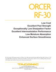
RF-35 is a ceramic filled, low-cost PTFE substrate. RF-35 not only satisfies the price requirement, but also<br />
exceeds every electrical and mechanical property that is sought in a PCB substrate f<strong>or</strong> high frequency<br />
applications. The dielectric constant is 3.5, with a tight tolerance (+/-0.1), offered in thicknesses that are<br />
increments of 10 mil [0.25 mm]. (RF-35 is currently offered in 10, 20, 30, and 60 mil [0.25 mm, 0.5 mm, 0.76<br />
mm & 1.52 mm]). With the introduction of RF-35P in January 2002 the same attributes are now available in<br />
increments of 2mil [0.05 mm]. RF-35P is available in laminate thicknesses of 2 mil, 4 mil, 6 mil & 8 mil [0.05<br />
mm, 0.10 mm, 0.15 mm & 0.20 mm]. The thickness tolerance f<strong>or</strong> RF-35 & RF-35P is per IPC-L-125, Class C<br />
(e.g., the tolerance f<strong>or</strong> a 0.020” [0.5mm] substrate is +/-0.0015”).<br />
RF-35 demonstrates exceptional thickness and dielectric constant variation within a sheet. The standard<br />
deviation of dielectric constant within a sheet is 0.01, and the standard deviation of the thickness within a<br />
sheet is 0.00023”. The loss tangent of RF-35, was measured at n = 1,2,3,… harmonic, and the frequency
anged from 500 MHz to 11.2 GHz. As the figure below indicates, there is virtually no variation in dielectric<br />
constant across the frequency spectrum, and the loss of RF-35 was 0.0018 at 1.9 GHz and 0.0025 at 10 GHz.<br />
Dk Versus Frequency f<strong>or</strong> RF-35<br />
Df Vs. Frequency f<strong>or</strong> RF-35<br />
N<strong>or</strong>malized Dk<br />
1.04<br />
1.02<br />
1<br />
0.98<br />
0.96<br />
0 2 4 6 8 10 12<br />
Frequency (GHz)<br />
Df<br />
0.003<br />
0.0025<br />
0.002<br />
0.0015<br />
0 1.5 3 4.5 6 7.5 9 10.5 12<br />
Frequency (GHz)<br />
The total loss in db/in versus frequency is also plotted:<br />
0<br />
Frequency Vs. Loss (db/in) f<strong>or</strong> RF-35<br />
(Microstrip Configuration, 30 Mil, 1/2 Oz Copper)<br />
db/in<br />
-0.1<br />
-0.2<br />
0 3 6 9 12<br />
Frequency (GHz)<br />
The water abs<strong>or</strong>ption is less than 0.02% when exposed to water f<strong>or</strong> 24 hours at 23 o C. RF-35 is available in<br />
½ oz, 1 oz and 2 oz copper, and the peel strength (after the RF-35 substrate is exposed to a solder float @<br />
550 o F [287 o C] f<strong>or</strong> 10 seconds) is greater than 8 pounds/inch [1.4 N/mm] f<strong>or</strong> ½ oz copper. To address the<br />
issue of the rigidity of the PCB substrate, a proprietary technology was used to utilize the structural integrity of<br />
the woven glass reinf<strong>or</strong>cement. As a result of this w<strong>or</strong>k, the hardness of the substrate was increased to 34, as<br />
measured by the Rockwell hardness scale. Furtherm<strong>or</strong>e, RF-35 was engineered to have the best dimensional<br />
stability. RF-35 has a dimensional change of 40 PPM in the X-axis (fill direction) and a dimensional change of<br />
-100 ppm in the Y-axis (warp direction) after etching the copper. These numbers, which translate into<br />
excellent registration in the finished substrates, are the best that can be found in any PCB substrate. The<br />
CTE in the Z axis f<strong>or</strong> RF-35 is 64 ppm/ o C, which ensures excellent reliability of the plated through holes. To<br />
ensure the mechanical integrity of RF-35 and to dispel the myth that PTFE substrates exhibits creep, RF-35<br />
was tested f<strong>or</strong> creep by an independent lab, acc<strong>or</strong>ding to BSI-125. The results are given below:
Percent Creep Vs. Temperature f<strong>or</strong> RF-35<br />
% Creep<br />
20<br />
0<br />
-20<br />
-40<br />
-60 0 100 200 300 400 500<br />
Temperature, C<br />
As the graph indicates RF-35 does not exhibit any creep/negligible creep when exposed to a load of 4200 psi,<br />
up to a temperature of 550 o F [287 o C]. This result indicates that RF-35 should not exhibit any creep in a<br />
n<strong>or</strong>mal PCB application.<br />
What makes RF-35 so unique? What gives RF-35 ALL the electrical and mechanical properties that RF<br />
designers look f<strong>or</strong>? The answer lies in the unique, proprietary process that <strong>Taconic</strong> has developed. By<br />
modifying the surface chemistry of the ceramic filler, <strong>Taconic</strong> has been able to get a true interpenetrating<br />
polymer netw<strong>or</strong>k of the ceramic filler and PTFE. This netw<strong>or</strong>k ensures that the ceramic particles are<br />
encapsulated with PTFE, which enables RF-35 to get the synergy effects of both, PTFE and the ceramic filler.<br />
Hence as explained above, RF-35 has the best dimensional stability, low CTE, an excellent mechanical<br />
integrity, a tight tolerance on DK and thickness, very high peel strength, and is the cheapest high perf<strong>or</strong>mance<br />
laminate available in the marketplace today. Furtherm<strong>or</strong>e, due to the inherent nature of PTFE, RF-35 has a<br />
flammability of UL-94 V0.<br />
Furtherm<strong>or</strong>e, a comparison of the processing steps f<strong>or</strong> RF-35 and f<strong>or</strong> a typical thermoset resin PCB material<br />
indicates that contrary to popular belief, processing RF-35 does not entail a complex process compared to<br />
processing a thermoset resin based PCB.<br />
PROCESS PROCESS SIGNIFICANCE RF-35 THERMOSETS<br />
Hole Quality -PTH Reliability Good Good<br />
Tool Life -Process Cost Good Po<strong>or</strong><br />
Burring -Added Process Good Po<strong>or</strong><br />
Hole Treatment -Added Process Fair Good<br />
PTH -PTH Quality Good Good<br />
Image, Etch -Trace/Line Definition Good Good<br />
Copper Plating -PTH Reliability Good Good<br />
Strip, Etch -Trace/Line Definition Good Good<br />
Solder Coating -Ease of soldering Good Good<br />
Depanelizing -Finished edge quality Good Good<br />
Routing Tool and Wear -Tool expense and replacement Fair Fair<br />
Routing Feed Rate -Routing cost Fair Fair<br />
Fixturing -Fixturing time and cost Fair Good<br />
Pick and Place -Ease and part location Fair Good<br />
Reflow Soldering -Warping and part integrity Fair Fair<br />
Mounting -Conf<strong>or</strong>mance to housing <strong>or</strong> pallet Good Fair
Conclusions:<br />
RF-35 does offer the combination of the best perf<strong>or</strong>mance and best price f<strong>or</strong> a high frequency application,<br />
indicating that a high perf<strong>or</strong>mance, low cost substrate is indeed a reality. As listed in the article, RF-35 offers<br />
all the electrical advantages of PTFE, all the mechanical advantages of the ceramic filler, negates all the<br />
disadvantages of PTFE substrates and disproves all the “myths” surrounding Teflon ® substrates and<br />
processing Teflon® substrates.