Instruction Manual - Dr. Fritz Faulhaber GmbH & Co. KG
Instruction Manual - Dr. Fritz Faulhaber GmbH & Co. KG
Instruction Manual - Dr. Fritz Faulhaber GmbH & Co. KG

You also want an ePaper? Increase the reach of your titles
YUMPU automatically turns print PDFs into web optimized ePapers that Google loves.
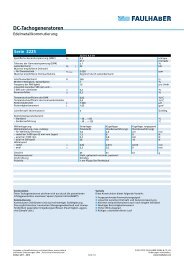
4 Functional Description<br />
4.2 <strong>Co</strong>nfiguration<br />
The control parameters of the SC speed controller integrated in the motor can be individually<br />
adjusted to the respective application via a PC. This requires a programming adapter which can be<br />
ordered separately as well as a version of the FAULHABER Motion Manager PC software suitable for<br />
the speed controller.<br />
The software is available on request or from the FAULHABER homepage<br />
www.faulhaber.com/MotionManager.<br />
CAUTION!<br />
Risk of damage<br />
Before starting up, the parameters configured in the control must be checked and if necessary adjusted.<br />
Incorrectly set values can cause irreparable damage to the motor and / or the speed controller.<br />
In particular, the following parameters must be correctly set:<br />
ffDuration and maximum current value,<br />
ffGenerator voltage constant kE and connected resistance R,<br />
ff<strong>Co</strong>ntroller parameter.<br />
The flat brushless DC motor is equipped with digital Hall sensors, with which the commutation<br />
signals can be determined. The actual speed value is determined via the time interval between the<br />
edges of the hall sensor signals.<br />
Preset default basic parameters:<br />
• Due to the resolution of the digital hall sensors, speeds from approx. 400 rpm can be stably controlled.<br />
• PWM frequency at the power output stage approx. 96 kHz.<br />
• 2-quadrant operation with function for quick speed reduction.<br />
The motor windings are short-circuited for faster transition from higher to lower speeds.<br />
Digital output<br />
Electronics supply<br />
Motor supply<br />
FG<br />
22 kΩ<br />
Up<br />
Umot<br />
Protection function:<br />
Overtemperature<br />
Setpoint input<br />
0 – 10 V DC<br />
Unsoll<br />
nsoll<br />
PI velocity<br />
controller<br />
3 Phase<br />
PWM<br />
Ua block<br />
commutator<br />
MOSFET<br />
Power<br />
output<br />
stage<br />
Phase A<br />
Phase B<br />
Phase C<br />
BL-Motor<br />
Rotational direction input<br />
DIR<br />
Evaluation<br />
rotational<br />
direction<br />
Speed<br />
calculation<br />
(t)<br />
Armature<br />
position<br />
calculation<br />
Hall sensor A<br />
Hall sensor B<br />
Hall sensor C<br />
I²t current<br />
limitation<br />
Iist Motor<br />
model<br />
5 V-<strong>Co</strong>ntrol<br />
VCC<br />
+5 V<br />
Microcontroller<br />
RM<br />
kE<br />
GND<br />
Signal GND<br />
15