Navien NP Condensing Tankless Gas Water Heater - Service Manual
Navien NP Condensing Tankless Gas Water Heater - Service Manual
Navien NP Condensing Tankless Gas Water Heater - Service Manual

You also want an ePaper? Increase the reach of your titles
YUMPU automatically turns print PDFs into web optimized ePapers that Google loves.
<strong>Service</strong> <strong>Manual</strong><br />
<strong>Service</strong> <strong>Manual</strong><br />
<strong>Service</strong> <strong>Manual</strong><br />
<strong>Tankless</strong> <strong>Gas</strong> <strong>Water</strong> <strong>Heater</strong><br />
<strong>Tankless</strong> <strong>Gas</strong> <strong>Water</strong> <strong>Heater</strong><br />
Ver. 2.00<br />
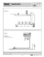
NR/<strong>NP</strong> <strong>Tankless</strong> <strong>Gas</strong> <strong>Water</strong> <strong>Heater</strong><br />
MODEL<br />
WARNING<br />
If the information in these instructions is not followed exactly, a fire or explosion may result<br />
causing property damage, personal injury or death.<br />
Do not store or use gasoline or other flammable vapors and liquids in the<br />
vicinity of this or any other appliance.<br />
NR/<strong>NP</strong> Series<br />
NR-180 <strong>NP</strong>-180 NR-180A <strong>NP</strong>-180A<br />
NR-210 <strong>NP</strong>-210 NR-210A <strong>NP</strong>-210A<br />
NR-240 <strong>NP</strong>-240 NR-240A <strong>NP</strong>-240A<br />
WHAT TO DO IF YOU SMELL GAS<br />
Do not try to light any appliance.<br />
Do not touch any electrical switch; do not use any phone in your building.<br />
Immediately call your gas supplier from a neighbor’s phone. Follow the gas supplier’s<br />
instructions.<br />
If you cannot reach your gas supplier, call the fire department.<br />
Installation and service must be performed by a qualified installer,<br />
service agency or the gas supplier.<br />
<strong>Navien</strong> America, Inc.<br />
20 Goodyear lrvine, CA 92618<br />
TEL +949-420-0420 FAX +949-420-0430<br />
www.naviennamerica.com<br />
2 nd Edition - July 2010<br />
No. 20A-GT-001
Contents<br />
REVISIONS 5<br />
NAVIEN WARRANTY 6<br />
HANDLING OF THIS MANUAL 9<br />
ABBREVIATION AND DEFINITION 10<br />
1. SAFETY CONSIDERATIONS 11<br />
1.1. SAFETY DEFINITIONS 11<br />
1.2. LIST OF SAFETY SYMBOLS IN THIS MANUAL 11<br />
1.3. SYMBOLS USED THE INSTRUCTIONS 11<br />
1.4. SAFETY PRECAUTIONS 12<br />
2. PRODUCT INFORMATION 17<br />
2.1. PRODUCT INFORMATION 17<br />
2.2. LAYOUT AND KEY COMPONENTS 18<br />
2.2.1. NR-A Model 18<br />
2.2.2. <strong>NP</strong>-A Model 19<br />
2.2.3. NR Model 20<br />
2.2.4. <strong>NP</strong> Model 21<br />
3. TECHNICAL DATA 22<br />
3.1. GENERAL SPECIFICATIONS 22<br />
3.2. DIMENSIONS 23<br />
3.2.1. NR-A, <strong>NP</strong>-A Model 23<br />
3.2.2. NR, <strong>NP</strong> Model 24<br />
4. SYSTEM DETAILS 25<br />
4.1. SCHEMATIC AND FLOW DIAGRAM 25<br />
4.1.1. NR-A Model 25<br />
4.1.2. <strong>NP</strong>-A Model 26<br />
4.1.3. NR Model 27<br />
4.1.4. <strong>NP</strong> Model 28<br />
4.2. OPERATION FLOW CHART 29<br />
4.3. DIP SWITCH SETTINGS 34<br />
4.4. WIRING DIAGRAM 36<br />
4.4.1. NR-A Model 36<br />
©<strong>Navien</strong> America Inc. 2010<br />
1<br />
NR/<strong>NP</strong> series service <strong>Manual</strong><br />
Version 2.0
4.4.2. <strong>NP</strong>-A Model 37<br />
4.4.3. NR Model 38<br />
4.4.4. <strong>NP</strong> Model 39<br />
4.5. ELECTRICAL DIAGNOSTIC POINTS 40<br />
4.6. KEY COMPONENTS DESCRIPTION 43<br />
4.6.1. PCB 43<br />
4.6.2. Thermal Fuse 44<br />
4.6.3. Transformer 45<br />
4.6.4. High Limit Switch or Exhaust Limit Switch 46<br />
4.6.5. Thermistor 47<br />
4.6.6. Fan motor 48<br />
4.6.7. Flame Rod Ass’y 49<br />
4.6.8. Ignition Transformer 50<br />
4.6.9. APS 51<br />
4.6.10. Manifold 52<br />
4.6.11. Main <strong>Gas</strong> Valve 53<br />
4.6.12. GPS 54<br />
4.6.13. Burner 55<br />
4.6.14. <strong>Water</strong> Adjustment Valve 56<br />
4.6.15. Flow Sensor 57<br />
4.6.16. Primary Heat Exchanger 58<br />
4.6.17. Seconary Heat Exchanger 59<br />
4.6.18. Buffer Tank (“A” Series) 60<br />
4.6.19. Circulation Pump (“A” Series) 61<br />
4.6.20. Bypass Mixing Valve (“Non-A” Series) 62<br />
5. TROUBLESHOOTING 63<br />
5.1. ERROR CODE LIST 63<br />
5.2. 01ERROR 65<br />
5.3. 03ERROR 67<br />
5.4. 04ERROR 75<br />
5.5. 07ERROR 77<br />
5.6. 08ERROR 79<br />
5.7. 09ERROR 81<br />
5.8. 10ERROR 84<br />
5.9. 12ERROR 88<br />
5.10. 15ERROR 91<br />
5.11. 16ERROR 92<br />
©<strong>Navien</strong> America Inc. 2010<br />
2<br />
NR/<strong>NP</strong> series service <strong>Manual</strong><br />
Version 2.0
5.12. 21ERROR 95<br />
5.13. 22ERROR 96<br />
5.14. 27ERROR 98<br />
5.15. 30ERROR 100<br />
5.16. 32ERROR 102<br />
5.17. 33ERROR 103<br />
5.18. 34ERROR 104<br />
5.19. 35ERROR 107<br />
5.20. 36ERROR 109<br />
5.21. 37ERROR 110<br />
5.22. 38ERROR 112<br />
5.24. 44ERROR 117<br />
5.25. 45ERROR 119<br />
5.26. 48ERROR 122<br />
5.27. TROUBLESHOOTING GUIDE BY SYMPTOM 124<br />
5.27.1. Noise 124<br />
5.27.2. Hot water 126<br />
5.27.3. Circuit breaker operates 127<br />
6. INSPECTION 128<br />
6.1. PREPARING THE WATER HEATER FOR INSPECTION 128<br />
6.2. MEASURING GAS PRESSURE SETTING 129<br />
6.2.1. How to Check Inlet <strong>Gas</strong> Pressure 129<br />
6.2.2. Adjusting the <strong>Gas</strong>-Air Ratio 130<br />
7. MAINTENANCE 132<br />
7.1. DRAINING THE WATER HEATER 132<br />
7.2. CLEANING THE INTAKE AIR FILTER 133<br />
7.3. FLUSHING THE HEAT EXCHANGER 134<br />
8. REPLACEMENT OF PARTS 135<br />
8.1. REPLACEMENT PROCEDURE 135<br />
8.2. COMPONENTS REPLACEMENT INSTRUCTIONS 136<br />
8.2.1. PCB 136<br />
8.2.2. Fuse 137<br />
8.2.3. Transformer 138<br />
8.2.4. Fan Motor(Combustion Air Blow) 139<br />
8.2.5. Flame Rod 140<br />
8.2.6. Ignition Transformer 141<br />
8.2.7. APS 142<br />
©<strong>Navien</strong> America Inc. 2010<br />
3<br />
NR/<strong>NP</strong> series service <strong>Manual</strong><br />
Version 2.0
8.2.8. Manifold 143<br />
8.2.9. Main <strong>Gas</strong> Valve 145<br />
8.2.10. GPS 147<br />
8.2.11. Condensation Trap 148<br />
8.2.12. <strong>Water</strong> Adjustment Valve 149<br />
8.2.13. Flow Sensor 150<br />
8.2.14. Buffer Tank (“A” Series) 151<br />
8.2.15. Circulation Pump (“A” Series) 152<br />
8.2.16. 3-way Valve (“A” Series) 154<br />
8.2.17. 2-way Valve (“<strong>NP</strong>-A” “<strong>NP</strong>” Series) 155<br />
8.2.18. Bypass Mixing Valve (“Non-A” Series) 156<br />
9. COMPONENTS DIAGRAM AND PART LIST 157<br />
9.1. CASE DISASSEMBLE (NR/<strong>NP</strong> – A, NR/<strong>NP</strong>) 157<br />
9.2. BURNER DISASSEMBLE (NR/<strong>NP</strong> – A, NR/<strong>NP</strong>) 159<br />
9.3. WATER WAY DISASSEMBLE (NR-A) 162<br />
9.4. WATER WAY DISASSEMBLE (NR) 163<br />
9.5. WATER WAY DISASSEMBLE (<strong>NP</strong>-A) 164<br />
9.6. WATER WAY DISASSEMBLE (<strong>NP</strong>) 165<br />
10. INSPECTION AND MAINTENANCE SCHEDULE 169<br />
10.1. ANNUAL SERVICING 169<br />
10.2. INSPECTION REPORT 170<br />
10.3. MAINTENANCE REPORT 171<br />
©<strong>Navien</strong> America Inc. 2010<br />
4<br />
NR/<strong>NP</strong> series service <strong>Manual</strong><br />
Version 2.0
Revisions<br />
Version Description of changes Date<br />
1.00<br />
2.00<br />
First Issue<br />
Format Revision<br />
04/27/10<br />
July/20/10<br />
©<strong>Navien</strong> America Inc. 2010<br />
5<br />
NR/<strong>NP</strong> series service <strong>Manual</strong><br />
Version 2.0
<strong>Navien</strong> Warranty<br />
CAUTION<br />
This product warranty is valid only used in the America and Canada but automatically<br />
be voided for the other counties (for America and Canada unit standard only).<br />
GENERAL<br />
<strong>Navien</strong> America, Inc. (<strong>Navien</strong>) warrants this <strong>Navien</strong> <strong>Water</strong> <strong>Heater</strong> and its component<br />
parts to be free from defects in materials and workmanship, under normal use and<br />
service, for the Applicable Warranty Period. At its option, <strong>Navien</strong> will replace the<br />
defective component part(s), in accordance with the terms of this Limited Warranty,<br />
if it fails in normal use and service during the Applicable Warranty Period.The<br />
replacement component part(s) must be <strong>Navien</strong> original factory component Part(s).<br />
The replacement component part(s) will be warranted only for the unexpired portion<br />
of the original component part’s Applicable Warranty Period.<br />
APPLICABLE WARRANTY PERIODS (* DHW means Domestic Hot <strong>Water</strong>)<br />
NR & <strong>NP</strong> Series<br />
Residential<br />
*DHW use only<br />
Heat Exchanger<br />
<strong>NP</strong> Series<br />
Commercial use Or<br />
Residential Space<br />
Heating use<br />
Period of Coverage<br />
NR & <strong>NP</strong> Series<br />
Residential<br />
DHW use only<br />
All other Parts and Components<br />
<strong>NP</strong> Series<br />
Commercial use Or<br />
Residential Space<br />
Heating use<br />
15 years 10 years 5 years 3 years<br />
IMPORTANT<br />
Proof of purchase is required to obtain warranty service. You can show proof of<br />
purchase with dated sales receipt, by completing and mailing the enclosed warranty<br />
registration card within 30 days of purchasing the product or by registering online at.<br />
www.navienamerica.com<br />
©<strong>Navien</strong> America Inc. 2010<br />
6<br />
NR/<strong>NP</strong> series service <strong>Manual</strong><br />
Version 2.0
EFFECTIVE DATE<br />
The Effective Date of warranty coverage (the beginning of the Applicable Warranty Periods) is the<br />
date of purchase of this water heater, if properly registered.<br />
HEAT EXCHANGER WARRANTY<br />
The Applicable Warranty Period for a NR & <strong>NP</strong> series Heat Exchanger failure installed in a Residential<br />
DHW application (including domestic recirculation) is Fifteen (15) years from the Effective<br />
Date. The Applicable Warranty Period for a <strong>NP</strong> series Heat Exchanger failure installed in a Commercial<br />
application or Residential “Combi (DHW and Space heating)” application is Ten (10)<br />
years from the Effective Date. For any Commercial application or Residential Combi application,<br />
a <strong>NP</strong> series unit is recommended. If a NR series unit is used in any Commercial application or<br />
Residential Combi application, the Applicable Warranty for a Heat Exchanger failure will be<br />
voided.<br />
PARTS WARRANTY (excluding heat exchanger)<br />
The Applicable Warranty Period for a NR & <strong>NP</strong> series Part(s) failure installed in a Residential<br />
DHW application (including domestic recircualtion) is Five(5) years from the Effective Date. The<br />
Applicable Warranty Period for a <strong>NP</strong> series Part(s) failure installed in a Commercial application or<br />
Residential Combi application is Three(3) years from the Effective Date. IF a NR unit is used in<br />
any Commercial application or Residential Combi application, the Applicable Warranty for a<br />
Part(s) failure will be voided.<br />
WATER HEATER SHOULD NOT BE USED FOR<br />
SPACE HEATING.(Only NR-(A) Series)<br />
The NR Series <strong>Water</strong> <strong>Heater</strong> should not used for space Heating and other heating. If NR Series<br />
<strong>Water</strong> <strong>Heater</strong> is used for space <strong>Heater</strong> and other heating, the applicable warranty will be voided.<br />
LABOR ALLOWANCE<br />
The Applicable Period for this Labor Allowance for all water heater models is One (1) year<br />
from the Effective Date. The payment and amount of any payment are subject to approval at<br />
Naiven’s sole discretion. The Labor Allowance will be paid based on <strong>Navien</strong>’s Schedule of<br />
Labor Allowances.<br />
TRANSFERABLILITY<br />
This warranty is offered to the original and subsequent owners of the water heater but is limited<br />
to the original address registered with the warranty only. The warranty will be void if the water<br />
heater is relocated to any other location.<br />
7<br />
©<strong>Navien</strong> America Inc. 2010<br />
NR/<strong>NP</strong> series service <strong>Manual</strong><br />
Version 2.0
WARRANTY EXCLUSIONS<br />
This warranty does not cover the following conditions:<br />
• Damages, malfunctions, or failures resulting from failure to install the water heater in<br />
accordance with applicable building codes, ordinances or normal plumbing and electrical<br />
trade practices.<br />
• Damages, malfunctions or failures resulting from improper installation or failure to operate<br />
and maintain the water heater in accordance with the manufacturer’s instructions<br />
provided.<br />
• Performance problems caused by improper sizing of the water heater or the gas supply<br />
line, the venting connection, combustion air openings, electric service voltage, wiring or<br />
fusing.<br />
• Damages, malfunctions or all failures caused by conversion from natural gas to LP gas<br />
or LP gas to natural gas or attempt to operate with a type of gas not specified for the<br />
water heater.<br />
• Damages, malfunctions or failures caused by operating the water heater with any parts<br />
removed or with parts that have been modified, altered or unapproved for installation.<br />
• Damages, malfunctions or failures caused by abuse, negligence, alteration, accident,<br />
fire, flood, freezing, lightning and other acts of God.<br />
• Heat Exchanger failures caused by operating the water heater in a corrosive or contaminated<br />
atmosphere.<br />
• Damages, malfunctions or failures caused by poor water quality, lime or mineral build-up<br />
or sediment build-up.<br />
• Damages, malfunctions or failures caused by operating the unit at water temperatures<br />
outside the factory calibrated temperature limits and/or exceeding the maximum setting<br />
of the high limit control.<br />
• Heat Exchanger failures caused by operating the water heater when it is not supplied with<br />
potable water at all times.<br />
• Damages, malfunctions or failures caused by subjecting the heat exchanger to pressures<br />
or firing rates greater or lesser than those shown on the rating plate.<br />
• Units installed outside of the fifty states (and the District of Columbia) of the United States<br />
of America and outside of Canada.<br />
• Rating plate has been removed by an unauthorized person. A water heater should not be<br />
operated if the rating plate has been removed.<br />
• Damage due to freezing.<br />
Product Disposal Measures<br />
Dispose of components of the heating system that require replacement in an environmentally<br />
responsible manner.<br />
Make sure that condensate disposal method is in accordance with local regulations.<br />
8<br />
©<strong>Navien</strong> America Inc. 2010<br />
NR/<strong>NP</strong> series service <strong>Manual</strong><br />
Version 2.0
Handling of This <strong>Manual</strong><br />
Scope<br />
• This <strong>Service</strong> <strong>Manual</strong> is applicable to <strong>Navien</strong> <strong>Tankless</strong> <strong>Water</strong> <strong>Heater</strong> NR/<strong>NP</strong> Series.<br />
Product Model discrimination label located in 2 places.<br />
<br />
Precautions for Handling of This <strong>Manual</strong><br />
• <strong>Navien</strong> America Inc. reserves all rights related to this manual<br />
• This manual should be accessible only to technical service personal authorized by<br />
<strong>Navien</strong> America Inc.<br />
• Read and understand the safety information before operating or servicing this<br />
<strong>Navien</strong> <strong>Water</strong> <strong>Heater</strong>.<br />
About Notation in the <strong>Manual</strong><br />
Indication of Refer To<br />
The “” mark is used to indicate the chapter or section you should refer to its format is<br />
as indicated below.<br />
{3.1 General Specification} of {3.1}<br />
©<strong>Navien</strong> America Inc. 2010<br />
9<br />
NR/<strong>NP</strong> series service <strong>Manual</strong><br />
Version 2.0
Abbreviation and Definition<br />
Abbreviation<br />
NR-A<br />
<strong>NP</strong>-A<br />
NR<br />
<strong>NP</strong><br />
“A” Series<br />
“Non-A” Series<br />
NG<br />
LP<br />
AP<br />
APS<br />
DHW<br />
FM<br />
GARC<br />
GPM<br />
GPS<br />
GV<br />
MGV<br />
MV<br />
SGV<br />
RPM<br />
WAV<br />
PCB<br />
EMI<br />
HTL<br />
Definition<br />
General name of NR-180A, NR-210A, and NR-240A<br />
General name of <strong>NP</strong>-180A, <strong>NP</strong>-210A and <strong>NP</strong>-240A<br />
General name of NR-180, NR-210, and NR-240<br />
General name of <strong>NP</strong>-180, <strong>NP</strong>-210, and <strong>NP</strong>-240<br />
General name of NR-A, and <strong>NP</strong>-A<br />
General name of NR, and <strong>NP</strong><br />
Natural <strong>Gas</strong><br />
Propane <strong>Gas</strong><br />
Air Pressure<br />
Air Pressure Sensor<br />
Domestic Hot <strong>Water</strong><br />
Fan Motor<br />
<strong>Gas</strong> Air Ratio Control<br />
Gallon per Minute<br />
<strong>Gas</strong> Pressure Sensor<br />
<strong>Gas</strong> Valve : Main and Solenoid<br />
Main <strong>Gas</strong> Valve<br />
Modulating Valve<br />
Solenoid <strong>Gas</strong> Valve<br />
Round per Minute<br />
<strong>Water</strong> Adjustment Valve<br />
Printed Circuit Board<br />
Electromagnetic Interface<br />
High Temperature Limiter<br />
©<strong>Navien</strong> America Inc. 2010<br />
10<br />
NR/<strong>NP</strong> series service <strong>Manual</strong><br />
Version 2.0
1. Safety Considerations<br />
1.1. Safety Definitions<br />
All Safety messages will refer to potential hazards. Precisely follow the instructions<br />
to avoid the risk of injury.<br />
This is the safety alert symbol. It is used to alert you of potential<br />
personal injury hazards. Observe all of the safety messages that<br />
follow this symbol to avoid possible injury of death.<br />
1.2. List of safety symbols in this manual<br />
DANGER<br />
WARNING<br />
Indicates an imminently hazardous situation which, if not avoided,<br />
could result in severe injury or death.<br />
Indicates a potential hazardous situation which, if not avoided, could<br />
result in injury or death.<br />
CAUTION<br />
Indicates an imminent hazardous situation which , if not avoided, may<br />
result in minor or moderate injury.<br />
CAUTION<br />
Used without the safety alert symbol indicates a potential hazardous<br />
situation which, if not avoided, could result in property damage.<br />
1.3. Symbols Used in the Instructions<br />
The following symbols are used throughout the instructions to bring attention to<br />
important information concerning the appliance.<br />
IMPORTANT<br />
Warns of a risk of material loss and environmental pollution.<br />
NOTE<br />
Indicates additional information that is important but not related to<br />
personal injury or property damage.<br />
©<strong>Navien</strong> America Inc. 2010<br />
11<br />
NR/<strong>NP</strong> series service <strong>Manual</strong><br />
Version 2.0
1.4. Safety Precautions<br />
DANGER<br />
FLAMMABLE MATERIALS<br />
Keep the area around the water heater clear and free from flammable materials.<br />
• DO NOT place flammable liquids such as oils or gasoline, etc. near the water<br />
heater.<br />
• DO NOT place combustibles such as newspapers and laundry etc. near the<br />
water heater or the venting system.<br />
• DO NOT place or use hair spray, spray paint or any other type of spray can<br />
near the water heater or the venting system (including the vent terminator).<br />
• DO NOT place anything in or around the vent terminals that could obstruct the<br />
air flow in and out of the water heater such as a clothes line.<br />
DANGER<br />
FLAMMABLE VAPORS<br />
Vapors from flammable liquids will<br />
explode and catch fire causing death or<br />
severe burns.<br />
Do not use or store flammable products<br />
such as gasoline, solvents or adhesives in<br />
the same room or area near the water<br />
heater<br />
Keep flammable<br />
products:<br />
far away from heater<br />
in approved containers,<br />
tightly closed, and out of<br />
children’s reach.<br />
<strong>Water</strong> heater has<br />
a main burner flame:<br />
which can come on at<br />
any time, and may ignite<br />
flammable vapors.<br />
Vapors:<br />
cannot be seen,<br />
are heavier than air,<br />
go a long way on the<br />
floor. And can be<br />
carried from other rooms<br />
to the main burner flame<br />
by air currents.<br />
©<strong>Navien</strong> America Inc. 2010<br />
12<br />
NR/<strong>NP</strong> series service <strong>Manual</strong><br />
Version 2.0
COMPROMISED VENTING SYSTEM<br />
DANGER<br />
• Failure to follow the Venting Section of the installation manual may result in the<br />
unsafe operation of this water heater. To avoid the risk of fire, explosion of<br />
asphyxiation from carbon monoxide, never operate the water heater unless it is<br />
properly vented to outside and has an adequate air supply for proper operation.<br />
• Be sure to inspect the vent terminator and the air intake pipe annually to ensure<br />
safe operation of the water heater.<br />
• Immediately turn off and do not use the water heater if any of the vent pipes, vent<br />
elbows and/or the water heater.<br />
i. damaged in any way,<br />
ii. have separated at a joint,<br />
iii. are cracked or show evidence of corrosion, rusting or melting.<br />
HOT WATER TEMPERATURE SETTING<br />
DANGER<br />
• <strong>Water</strong> temperature over 125 can cause severe burns<br />
instantly or death from scalds.<br />
• Households with small children, disabled, or elderly<br />
persons may require 120 or lower temperature setting to<br />
prevent contact with “HOT” water.<br />
• To prevent scalding, check water temperature after servicing.<br />
• If the proposed water heater outlet temperature is above 125, a thermostatically<br />
controlled mixing valve or temperature limiting valve should be considered to<br />
reduce the risk of scalding. Contact a licensed plumber or the local plumbing<br />
authority for further information.<br />
• This <strong>Navien</strong> <strong>Water</strong> <strong>Heater</strong> is factory se at 120 (<strong>NP</strong> Series: 140) for your safety<br />
and comfort. Increasing the set temperature increases the risk of accidental<br />
scalding. Consult the chart below before you decide to adjust the set temperature.<br />
©<strong>Navien</strong> America Inc. 2010<br />
13<br />
NR/<strong>NP</strong> series service <strong>Manual</strong><br />
Version 2.0
DANGER<br />
WHAT TO DO IF YOU SMELL GAS<br />
If you do not follow these instructions exactly, a fire or explosion may result causing<br />
property damage, personal injury or loss of life.<br />
DO NOT OPERATE THE WATER HEATER.<br />
DO NOT OPERATE ANY FAUCETS.<br />
Smell all around the appliance area for gas. Be sure to smell next to the floor<br />
because some gas is heavier than air and will settle on the floor.<br />
• Do not smoke.<br />
• Extinguish any open flames and sparks.<br />
• Do not operate light switches or electrical equipment switches.<br />
• Do not use any phone in your building.<br />
• Open the windows and doors.<br />
• Close the gas shutoff valve.<br />
• Keep people away from the danger zone.<br />
• Observe the safety regulations of your local gas supplier, found on the gas<br />
meter.<br />
• Immediately call your gas supplier from the outside of the building.<br />
Follow the gas supplier’s instructions.<br />
• If you cannot reach your gas supplier, call the fire department.<br />
• Notify your plumbing/ heating contractor from the outside of the building.<br />
©<strong>Navien</strong> America Inc. 2010<br />
14<br />
NR/<strong>NP</strong> series service <strong>Manual</strong><br />
Version 2.0
IMPORTANT SAFETY PREAUTIONS<br />
DANGER<br />
• Read and understand this safety information before operating or servicing this<br />
<strong>Navien</strong> <strong>Water</strong> <strong>Heater</strong>.<br />
• This manual must remain with the <strong>Navien</strong> <strong>Water</strong> <strong>Heater</strong>.<br />
• Confirm the location of the gas shut-off valve. Close the manual shut-off valve<br />
if the <strong>Navien</strong> <strong>Water</strong> <strong>Heater</strong> over becomes subjected to overheating, fire, flood,<br />
physical damage or any other such damaging condition during servicing.<br />
• DO NOT turn on the water heater unless water and gas supplies are fully<br />
opened.<br />
• DO NOT turn on the water heater if cold water supply shut-off valve is closed.<br />
• Make certain power to water heater is “OFF” before removing the front cover for<br />
any reason.<br />
• Label all wires prior to disconnection when servicing controls. Wiring errors<br />
can cause improper and dangerous operation. Verify proper operation after<br />
servicing.<br />
• Improper adjustment, alteration, service or maintenance can cause property<br />
damage, personal injury, or death.<br />
• To prevent scalding, always check the temperature of the hot water afterservicing.<br />
• DO NOT attempt to change the water temperature while someone is using the<br />
water heater.<br />
• DO NOT use parts other than those specified for this equipment.<br />
• DO NOT operate the water heater if you feel something is wrong with the unit.<br />
• DO NOT allow children to operate or otherwise handle the unit.<br />
DANGER<br />
INSTALLATION REQUIRMENT<br />
• Installation condition may affect the servicing. Read all related information in the<br />
“<strong>Condensing</strong> <strong>Water</strong> <strong>Heater</strong> <strong>Manual</strong>”.<br />
• The <strong>Navien</strong> <strong>Water</strong> <strong>Heater</strong>s must be installed according to all local and state<br />
codes or, in the absence of local and state codes, the most recent edition of the<br />
“National Fuel <strong>Gas</strong> Code (ANSI Z223.1/NFPA 54)” in the USA or the “National<br />
<strong>Gas</strong> and Propane Installation Code (CAN/CSA B 149.1)” in Canada.<br />
• Massachusetts code requires this water heater to be installed in accordance<br />
with Massachusetts Plumbing and Fuel <strong>Gas</strong> Code 248 CMR Section 2.00 and<br />
5.00.<br />
©<strong>Navien</strong> America Inc. 2010<br />
15<br />
NR/<strong>NP</strong> series service <strong>Manual</strong><br />
Version 2.0
GAS TYPE and AC VOLTAGE<br />
WARNING<br />
<strong>Navien</strong> units come from the factory configured for use with either Liquid Propane<br />
(LP) or Natural <strong>Gas</strong> (NG).<br />
Before starting the servicing, check the rating plate located on the side of the<br />
<strong>Water</strong> <strong>Heater</strong> to ensure the unit matches gas type, gas pressure, water pressure<br />
and electrical supply.<br />
Be sure the gas type and electricity voltage match the Rating Plate.<br />
• Use only the same gas type indicated on the rating plate of the <strong>Navien</strong> <strong>Water</strong><br />
<strong>Heater</strong>. Using different gas type will cause abnormal combustion and water<br />
heater malfunction.<br />
• Be sure to use 120 VAD, 60 Hz, minimum 2 A current. Using abnormally high<br />
or low AC voltage may cause abnormal operation, and may reduce the life<br />
expectancy of this product.<br />
If the unit does not match requirements, do not service, please contact<br />
<strong>Navien</strong> immediately.<br />
WARNING<br />
GAS CONVERSION<br />
Conversion of this unit from natural gas to propane or vice versa cannot be done<br />
in the field. Please reconfirm gas type on the rating plate (left side of unit) before<br />
servicing. DO NOT attempt any field conversion, this will result in dangerous<br />
operating conditions and will void all warranty.<br />
<strong>Navien</strong> America Inc. is not liable for any property damage and/of personal<br />
injury resulting from unauthorized conversions.<br />
©<strong>Navien</strong> America Inc. 2010<br />
16<br />
NR/<strong>NP</strong> series service <strong>Manual</strong><br />
Version 2.0
2. Product Information<br />
2.1. Product Information<br />
<strong>Navien</strong> offers two series of tankless gas water heater; <strong>Navien</strong> Regular (NR) as<br />
residential models and <strong>Navien</strong> Premium (<strong>NP</strong>) as commercial models. Each series<br />
in-cludes the “A” model with an optional built-in Circulation Pump and a Mini<br />
Buffer Tank. In addition, depending on the heat capacity, each model is divided<br />
into three types; 180,210,and240(*).<br />
NR<br />
<strong>NP</strong><br />
Items<br />
“A” Series<br />
(180/210/240)<br />
“Non-A”<br />
Series<br />
(180/210/240)<br />
“A” Series<br />
(180/210/240)<br />
“Non-A”<br />
Series<br />
(180/210/240)<br />
Intended Use<br />
DHW Only<br />
DHW<br />
Space Heating<br />
Commercial Applications<br />
Built-in<br />
Circulation Pump<br />
and Mini Buffer Tank<br />
Yes No Yes No<br />
Default<br />
Temperature<br />
120(49)<br />
140 (60)<br />
<strong>Gas</strong> Type<br />
NG, LP<br />
*.for details of the specifications, {5.1 General Specifications}<br />
©<strong>Navien</strong> America Inc. 2010<br />
17<br />
NR/<strong>NP</strong> series service <strong>Manual</strong><br />
Version 2.0
2.2. Layout and Key Components<br />
2.2.1. NR-A Model<br />
No Description <strong>Navien</strong> Part No. No Description <strong>Navien</strong> Part No.<br />
1 Intake Air Duct BH2505400B 16 WAV NCVM9EX00005<br />
2 Fan Motor NAFA9GLPCT01 17 Transformer BH1205008A<br />
3 Buffer Tank PASNCWBFTANK_001 18 Exhaust Limit Switch BH1401027A<br />
4 Flow Sensor BH1406004F 19 Secondary H/E -<br />
5 PCB Board NACR1GS32410 20 Primary H/E -<br />
6 Circulation Pump NAPU9GLPCT01 21 Ignition Transformer BH1201041D<br />
7 DHW Supply Adapter BH2507348B 22 APS Venturi BH2501413A<br />
8 3-Way Valve BH2507467C 23 Manifold PABCR180AMF_001<br />
9 DHW Inlet Adapter BH2507469A 24 Burner PABNCN30KDBN_003<br />
10 Syphon BH2507442C 25 APS NASS9EX00009<br />
11 <strong>Gas</strong> Inlet Adapter BH2507396A 26 Exhaust Duct BH2544004F<br />
12 Main <strong>Gas</strong> valve BH0901018A 27 Exhaust Pipe BH2505401B<br />
13 GPS Venturi BH2507359B 28 Air Intake Guide BH2543002C<br />
14 <strong>Gas</strong> Pipe BH2507509A 29 Power Switch BH1426002A<br />
15 GPS NASS9EXGPS01 30 <strong>Water</strong> Leakage Detector -<br />
©<strong>Navien</strong> America Inc. 2010<br />
18<br />
NR/<strong>NP</strong> series service <strong>Manual</strong><br />
Version 2.0
2.2.2. <strong>NP</strong>-A Model<br />
No Description <strong>Navien</strong> Part No. No Description <strong>Navien</strong> Part No.<br />
1 Intake Air Duct BH2505400B 17 Transformer BH1205008A<br />
2 Fan Motor NAFA9GLPCT01 18 Exhaust Limit Switch BH1401027A<br />
3 Buffer Tank PASNCWBFTANK_001 19 Secondary H/E -<br />
4 Flow Sensor BH1406004F 20 Primary H/E -<br />
5 PCB Board NACR1GS32410 21 Ignition Trans BH1201041D<br />
6 Circulation Pump NAPU9GLPCT01 22 APS Venturi BH2501413A<br />
7 DHW Supply Adapter BH2507348B 23 Manifold PABCR180AMF_001<br />
8 3-Way Valve BH2507467C 24 Burner PABNCN30KDBN_003<br />
9 DHW Inlet Adapter BH2507469A 25 APS NASS9EX00009<br />
10 Syphon BH2507442C 26 Exhaust Duct BH2544004F<br />
11 <strong>Gas</strong> Inlet Adapter BH2507396A 27 Exhaust Pipe BH2505401B<br />
12 Main <strong>Gas</strong> valve BH0901018A 28 Air Intake Guide BH2543002C<br />
13 GPS Venturi BH2507359B 29 Power Switch BH1426002A<br />
14 <strong>Gas</strong> Pipe BH2507351A 30 <strong>Water</strong> Leakage Detector -<br />
15 GPS NASS9EXGPS01<br />
16 2-Way Valve BH0914002B<br />
31 WAV NCVM9EX00005<br />
©<strong>Navien</strong> America Inc. 2010<br />
19<br />
NR/<strong>NP</strong> series service <strong>Manual</strong><br />
Version 2.0
2.2.3. NR Model<br />
No Description <strong>Navien</strong> Part No. No Description <strong>Navien</strong> Part No.<br />
1 Intake Duct BH2505400B 17 Transformer BH1205008A<br />
2 Fan Motor NAFA9GLPCT01 18 Exhaust Limit Switch BH1401027A<br />
3 Flow Sensor BH1406004F 19 Secondary H/E -<br />
4 Power Switch BH1426003A 20 Primary H/E -<br />
5 PCB Board NACR1GS32401 21 Ignition Trans BH1201041D<br />
6 <strong>Heater</strong> BH1501047B 22 APS Venturi BH2501413A<br />
7 <strong>Heater</strong> Clip BH2507447A 23 Manifold PABCR180AMF_001<br />
8 DHW Supply Adapter BH2507348B 24 Burner PABNCN30KDBN_003<br />
9 DHW Inlet Adapter BH2507469A 25 APS NASS9EX00009<br />
10 Syphon BH2507452C 26 Exhaust Duct BH2544004F<br />
11 <strong>Gas</strong> Inlet Adapter BH2507396A 27 Exhaust Pipe BH2505401B<br />
12 Main <strong>Gas</strong> valve BH0901018A 28 Air Intake Guide BH2543002C<br />
13 GPS Venturi BH2507359B 29 Bypass Mixing Valve AAVC9EXMIX01<br />
14 <strong>Gas</strong> Pipe BH2507351A 30 Freeze Protect Switch BH1402001A<br />
15 GPS NASS9EXGPS01<br />
16 WAV NCVM9EX00005<br />
31 Mixing Trans BH1205013A<br />
©<strong>Navien</strong> America Inc. 2010<br />
20<br />
NR/<strong>NP</strong> series service <strong>Manual</strong><br />
Version 2.0
2.2.4. <strong>NP</strong> Model<br />
No Description <strong>Navien</strong> Part No. No Description <strong>Navien</strong> Part No.<br />
1 Intake Air Duct BH2505400B 17 Transformer BH1205008A<br />
2 Fan Motor NAFA9GLPCT01 18 Exhaust Limit Switch BH1401027A<br />
3 Flow Sensor BH1406004F 19 Secondary H/E -<br />
4 Power Switch BH1426003A 20 Primary H/E -<br />
5 PCB Board NACR1GS32401 21 Ignition Trans Bh1201041D<br />
6 <strong>Heater</strong> BH1501047B 22 APS Venturi BH2501413A<br />
7 <strong>Heater</strong> Clip BH2507447A 23 Manifold PABCR180AMF_001<br />
8 DHW Supply Adapter BH2507348B 24 Burner PABNCN30KDBN_003<br />
9 DHW Inlet Adapter BH2507469A 25 APS NASS9EX00009<br />
10 Syphon BH2507452C 26 Exhaust Duct BH2544004F<br />
11 <strong>Gas</strong> Inlet Adapter BH2507396A 27 Exhaust Pipe BH2505401B<br />
12 Main <strong>Gas</strong> valve BH0901018A 28 Air Intake Guide BH2543002C<br />
13 GPS Venturi BH2507359B 29 WAV NCVM9EX00005<br />
14 <strong>Gas</strong> Pipe BH2507351A 30 Freeze Protect Switch BH1402001A<br />
15 GPS NASS9EXGPS01 31 Bypass Mixing Valve AAVC9EXMIX01<br />
16 2-Way Valve BH0914002B 32 Mixing Trans BH1205013A<br />
21<br />
©<strong>Navien</strong> America Inc. 2010 NR/<strong>NP</strong> series service <strong>Manual</strong> Version 2.0
3. Technical Data<br />
3.1. General Specifications<br />
Item NR,<strong>NP</strong>-180(A) NR,<strong>NP</strong>-210(A) NR,<strong>NP</strong>-240(A)<br />
Heat Capacity<br />
(Input)<br />
Natural <strong>Gas</strong><br />
LP <strong>Gas</strong><br />
Min: 15,000 Btuh<br />
Max: 150,000 Btuh<br />
Min: 15,000 Btuh<br />
Max: 150,000 Btuh<br />
Min: 17,000 Btuh<br />
Max: 180,000 Btuh<br />
Min: 17,000 Btuh<br />
Max: 180,000 Btuh<br />
Min: 17,000 Btuh<br />
Max: 199,000 Btuh<br />
Min: 17,000 Btuh<br />
Max: 199,000 Btuh<br />
Heat Capacity<br />
(Input)<br />
35°F Rise<br />
45°F Rise<br />
77°F Rise<br />
Dimensions<br />
Weight NR/<strong>NP</strong>-A<br />
Weight NR/<strong>NP</strong><br />
Installation Type<br />
Venting Type<br />
Ignition<br />
<strong>Water</strong> Pressure (min-max)<br />
<strong>Gas</strong> Supply<br />
Pressure<br />
Min. ~ Max.<br />
8.3 Gal/m<br />
6.5 Gal/m<br />
3.8 Gal/m<br />
W17” x H28”x D14”<br />
77 lbs<br />
67 lbs<br />
NG: 6”~10.5” W.C<br />
LP: 9”~13.5” W.C<br />
10.0 Gal/m<br />
7.7 Gal/m<br />
4.5 Gal/m<br />
W17” x H28”x D15”<br />
86 lbs<br />
77 lbs<br />
Indoor / Outdoor Wall-Hung<br />
Forced Draft Direct Vent<br />
Electronic Ignition<br />
15 – 150 PSI<br />
NG: 5”~10.5” W.C<br />
LP: 8”~13.5” W.C<br />
11 Gal/m<br />
8.6 Gal/m<br />
5.0 Gal/m<br />
W17” x H28” x D15”<br />
86 lbs<br />
77 lbs<br />
Manifold <strong>Gas</strong><br />
Pressure<br />
Min.<br />
Max.<br />
NG: 0.4” W.C<br />
LP: 0.8” W.C<br />
NG: 4.9” W.C<br />
LP: 7.6” W.C<br />
NG: 0.4” W.C<br />
LP: 0.8” W.C<br />
NG: 3.5” W.C<br />
LP: 5.9” W.C<br />
NG: 0.6” W.C<br />
LP: 1.0” W.C<br />
NG: 3.7” W.C<br />
LP: 3.7” W.C<br />
Minimum Flow Rate<br />
0 GPM for “A” models (no minimum flow rate requirement);<br />
0.5 GPM for Non-“A” models<br />
Connection Sizes<br />
Recirculation : “A” Model<br />
Cold <strong>Water</strong><br />
3/4” <strong>NP</strong>T<br />
Hot <strong>Water</strong><br />
3/4” <strong>NP</strong>T<br />
Recircualation<br />
3/4” <strong>NP</strong>T<br />
<strong>Gas</strong> Supply<br />
3/4” <strong>NP</strong>T<br />
Temperature<br />
Range (R/C)<br />
Thermisters<br />
Q’ty<br />
98 ~ 140(37 ~ 60)<br />
98 ~ 185(37 ~ 85)<br />
3 Thermisters (In, Out 1, Out 2)<br />
4 Thermisters (In, Out 1, Out 2, Mixing)<br />
Freeze<br />
Protection<br />
Auto Firing System (Internal or External Recirculation)<br />
Ceramic <strong>Heater</strong>s<br />
©<strong>Navien</strong> America Inc. 2010<br />
22<br />
NR/<strong>NP</strong> series service <strong>Manual</strong><br />
Version 2.0
3.2. Dimensions<br />
3.2.1. NR-A, <strong>NP</strong>-A Model<br />
1) Connection Diameter<br />
A<br />
B<br />
C<br />
D<br />
E<br />
F<br />
Description<br />
Exhaust<br />
Air Intake<br />
Hot <strong>Water</strong> Outlet<br />
Recirculation Inlet<br />
Cold <strong>Water</strong> Inlet<br />
<strong>Gas</strong> Connection<br />
Diameter<br />
3”<br />
3”<br />
3/4”<br />
3/4”<br />
3/4”<br />
3/4”<br />
2) Dimensions<br />
Model<br />
<br />
<br />
<br />
<br />
<br />
<br />
<br />
<br />
<br />
<br />
<br />
<br />
<br />
<br />
<br />
©<strong>Navien</strong> America Inc. 2010<br />
23<br />
NR/<strong>NP</strong> series service <strong>Manual</strong><br />
Version 2.0
3.2.2. NR, <strong>NP</strong> Model<br />
1) Connection Diameter<br />
A<br />
B<br />
C<br />
D<br />
E<br />
Description<br />
Exhaust<br />
Air Intake<br />
Hot <strong>Water</strong> Outlet<br />
Cold <strong>Water</strong> Inlet<br />
<strong>Gas</strong> Connection<br />
Diameter<br />
3”<br />
3”<br />
3/4”<br />
3/4”<br />
3/4”<br />
2) Dimensions<br />
Model<br />
<br />
<br />
<br />
<br />
<br />
<br />
<br />
<br />
<br />
<br />
<br />
<br />
<br />
<br />
<br />
©<strong>Navien</strong> America Inc. 2010<br />
24<br />
NR/<strong>NP</strong> series service <strong>Manual</strong><br />
Version 2.0
4. System Details<br />
4.1. Schematic and Flow Diagram<br />
4.1.1. NR-A Model<br />
Exhaust pipe<br />
intake air duct<br />
Fan motor<br />
Manifold<br />
Burner<br />
Primaty H/E<br />
Buffer tank<br />
Secondary H/E<br />
Flow sensor<br />
Check v/v<br />
Circulation pump<br />
<strong>Water</strong> adjustment v/v<br />
Main gas v/v<br />
3-Way v/v<br />
Hot water<br />
supply<br />
Recirculation<br />
Cold water<br />
supply<br />
Fuel gas<br />
inlet<br />
©<strong>Navien</strong> America Inc. 2010<br />
25<br />
NR/<strong>NP</strong> series service <strong>Manual</strong><br />
Version 2.0
4.1.2. <strong>NP</strong>-A Model<br />
Exhaust pipe<br />
intake air duct<br />
Fan motor<br />
Manifold<br />
Burner<br />
Primaty H/E<br />
Buffer tank<br />
<strong>Water</strong> adjustment v/v<br />
Secondary H/E<br />
Flow sensor<br />
Check v/v<br />
Circulation pump<br />
2-Way v/v<br />
Main gas v/v<br />
3-Way v/v<br />
Hot water<br />
supply<br />
Recirculation<br />
Cold water<br />
supply<br />
Fuel gas<br />
inlet<br />
©<strong>Navien</strong> America Inc. 2010<br />
26<br />
NR/<strong>NP</strong> series service <strong>Manual</strong><br />
Version 2.0
4.1.3. NR Model<br />
Exhaust pipe<br />
intake air duct<br />
Fan motor<br />
Manifold<br />
Burner<br />
Primaty H/E<br />
Bypass Mixing v/v<br />
Secondary H/E<br />
Flow sensor<br />
<strong>Water</strong> adjustment v/v<br />
Main gas v/v<br />
Hot water<br />
supply<br />
Cold water<br />
supply<br />
Fuel gas<br />
inlet<br />
©<strong>Navien</strong> America Inc. 2010<br />
27<br />
NR/<strong>NP</strong> series service <strong>Manual</strong><br />
Version 2.0
4.1.3. NR Model<br />
Exhaust pipe<br />
Intake air duct<br />
Fan motor<br />
Manifold<br />
Burner<br />
Primaty H/E<br />
Bypass Mixing v/v<br />
<strong>Water</strong> adjustment v/v<br />
Secondary H/E<br />
Flow sensor<br />
2-Way v/v<br />
Main gas v/v<br />
Hot water<br />
supply<br />
Cold water<br />
supply<br />
Fuel gas<br />
inlet<br />
©<strong>Navien</strong> America Inc. 2010<br />
28<br />
NR/<strong>NP</strong> series service <strong>Manual</strong><br />
Version 2.0
4.2. Operation Flow Chart<br />
Power ON<br />
System lnitalization<br />
Faucet Open<br />
Stand-by<br />
Faucet Close<br />
Flow Sensor<br />
>= 0.53 GPM<br />
NO<br />
MGV OFF<br />
MGV OFF<br />
YES<br />
Flame On:<br />
YES<br />
SGV1 OFF<br />
SGV1 OFF<br />
NO<br />
B<br />
SGV2 OFF<br />
SGV2 OFF<br />
Pre-Purge<br />
Watch-dog OFF<br />
MV OFF<br />
No Air Check:<br />
APS normal?<br />
YES<br />
Watch-dog ON<br />
D<br />
NO<br />
YES<br />
Igniter OFF<br />
GV/Igniter Power<br />
OFF<br />
NO<br />
Post-Purge: 10 sec<br />
DHW Waiting:<br />
Fan Motor ON for 300 sec<br />
Fan Motor ON/<br />
AP Check<br />
Flame ON?<br />
NO<br />
YES<br />
NO<br />
MGV OFF?<br />
YES<br />
FM start-up:<br />
FM and AP normal?<br />
YES<br />
Burner Start-up<br />
GV/Igniter Power<br />
ON<br />
Igniter ON<br />
C<br />
NO<br />
B<br />
Flow Sensor<br />
>= 0.53 GPM<br />
Lock-out:<br />
004E<br />
Lock-out:<br />
015E<br />
NO<br />
NO<br />
NO<br />
NO<br />
SGV1 OFF?<br />
YES<br />
SGV2 OFF?<br />
YES<br />
Igniter OFF?<br />
YES<br />
Flow Sensor<br />
>= 0.53 GPM<br />
YES<br />
Igniter ON<br />
for 1 sec?<br />
NO<br />
Lock-out:<br />
027E<br />
C<br />
YES<br />
Igniter OFF<br />
Lock-out:<br />
009E<br />
FM Control<br />
Lock-out:<br />
010E<br />
APS<br />
normal?<br />
NO<br />
YES<br />
©<strong>Navien</strong> America Inc. 2010<br />
29<br />
NR/<strong>NP</strong> series service <strong>Manual</strong><br />
Version 2.0
YES<br />
GPS<br />
normal?<br />
YES<br />
MGV ON<br />
NO<br />
Lock-out:<br />
035E<br />
Igniter ON<br />
MV ON<br />
D<br />
NO<br />
Flame ON<br />
during 10sec?<br />
NO<br />
Ignition Failure<br />
straight 3 times?<br />
YES<br />
Lock-out:<br />
003E<br />
YES<br />
Igniter ON for 1sec<br />
after Flame ON?<br />
YES<br />
Igniter OFF<br />
NO<br />
Igniter ON<br />
Burner Operation<br />
Faucet Close<br />
Flow Sensor<br />
>= 0.53 GPM<br />
YES<br />
D<br />
NO<br />
Flame OFF?<br />
NO<br />
YES<br />
Flame OFF straight 20 times during<br />
burner operation?<br />
YES<br />
Lock-out:<br />
012E<br />
FM start-up:<br />
FM and AP normal?<br />
YES<br />
Lock-out:<br />
009E<br />
NO<br />
Excess Air Pressure?<br />
YES<br />
Lock-out:<br />
010E<br />
NO<br />
APS normal?<br />
NO<br />
GPS normal?<br />
NO<br />
YES<br />
YES<br />
Lock-out:<br />
027E<br />
Lock-out:<br />
035E<br />
B<br />
GARC<br />
©<strong>Navien</strong> America Inc. 2010<br />
30<br />
NR/<strong>NP</strong> series service <strong>Manual</strong><br />
Version 2.0
HC minimum range?<br />
NO<br />
HC minimum range?<br />
NO<br />
HC minimum range?<br />
YES<br />
YES<br />
SV1 OFF<br />
SV1 ON<br />
SV1 ON<br />
SV2 OFF<br />
SV2 OFF<br />
SV2 ON<br />
SGV1 OFF?<br />
YES SGV2 OFF? YES Igniter OFF? YES<br />
NO<br />
NO<br />
SGV2 OFF?<br />
YES<br />
Igniter OFF?<br />
YES<br />
NO<br />
Igniter OFF?<br />
YES<br />
NO<br />
NO<br />
NO<br />
HC
B<br />
Lock-out<br />
Outlet Thermistor<br />
>= 208<br />
YES<br />
Lock-out:<br />
001E<br />
MGV OFF<br />
NO<br />
Outlet Thermistor<br />
>= 14<br />
NO<br />
YES<br />
Lock-out:<br />
007E<br />
SGV1 OFF<br />
SGV2 OFF<br />
Outlet Thermistor<br />
>= 248<br />
YES<br />
Lock-out:<br />
008E<br />
Watch-dog OFF<br />
NO<br />
NO<br />
Control Board<br />
Abnormal?<br />
YES<br />
Lock-out:<br />
015E<br />
Igniter OFF<br />
NO<br />
High-Limit-Switch 1<br />
Open?<br />
NO<br />
YES<br />
Lock-out:<br />
016E<br />
GV/Igniter Power OFF<br />
B<br />
Inlet Thermistor 1<br />
>= 14<br />
NO<br />
YES<br />
Lock-out:<br />
021E<br />
Main Power<br />
Reset?<br />
inlet Thermistor 1<br />
>= 248<br />
YES<br />
Lock-out:<br />
022E<br />
YES<br />
Power ON<br />
NO<br />
High-Limit-Switch 2<br />
Open?<br />
YES<br />
Lock-out:<br />
030E<br />
NO<br />
Inlet Thermistor 2<br />
>= 14<br />
YES<br />
Lock-out:<br />
032E<br />
PUMP Abnormal?<br />
YES<br />
Lock-out:<br />
038E<br />
NO<br />
NO<br />
Inlet Thermistor 2<br />
>= 248<br />
YES<br />
Lock-out:<br />
033E<br />
Mixing Valve Abnormal?<br />
YES<br />
Lock-out:<br />
045E<br />
NO<br />
NO<br />
Outlet Thermistor 2<br />
>= 14<br />
YES<br />
Lock-out:<br />
041E<br />
Cascade Connection<br />
Abnormal?<br />
YES<br />
Lock-out:<br />
043E<br />
NO<br />
Outlet Thermistor 2<br />
>= 248<br />
YES<br />
Lock-out:<br />
042E<br />
NO<br />
Thermistor Connection<br />
Abnormal?<br />
NO<br />
YES<br />
Lock-out:<br />
044E<br />
©<strong>Navien</strong> America Inc. 2010<br />
32<br />
NR/<strong>NP</strong> series service <strong>Manual</strong><br />
Version 2.0
Operation<br />
1. <strong>Water</strong> Flow Begins<br />
• <strong>Water</strong> Flow Sensor sends pulses to the PCB.<br />
• PCB senses flow greater than 0.5 GPM (0 GPM for “A” Model) (approximate).<br />
• Firing Sequence begins.<br />
2. Firing Sequence<br />
• PCB monitors Inlet / Outlet water temperature, temperature set point,<br />
and water flow rate.<br />
• Fan Motor energized. Purges combustion chamber.<br />
• Spark igniter begins sparking<br />
• Main <strong>Gas</strong> control valve opens to minimum fire rate.<br />
• Flame rod proves ignition.<br />
• Spark igniter stops sparking.<br />
3. Normal Operation<br />
• PCB monitors flame rod, fan motor frequency, outlet water temperature,<br />
PCB temperature set point and water flow rate.<br />
• Main <strong>Gas</strong> control valve modulates gas input to required firing rate.<br />
• Combustion fan speed is adjusted for the required firing rate.<br />
• <strong>Water</strong> adjustment valve is adjusted as needed.<br />
4. Shut-down Sequence<br />
• PCB senses flow rate less than 0.5 GPM (0 GPM for “A” Model) (approximate).<br />
• Main <strong>Gas</strong> Control valve closes.<br />
• <strong>Water</strong> adjustment valve resets to standby position.<br />
• Combustion fan runs for a short period of time at low speed.<br />
5. Standby Mode<br />
• PCB monitors water temperature and remote controls.<br />
• Freeze protection is activated as needed.<br />
33<br />
©<strong>Navien</strong> America Inc. 2010<br />
NR/<strong>NP</strong> series service <strong>Manual</strong><br />
Version 2.0
4.3. Dip Switch Settings<br />
There are two sets of Dip switches on the PCB.<br />
One set has 6 switches and the other has 8 switches.<br />
# 1 Dip switches<br />
ON<br />
# 2 Dip switches<br />
ON<br />
<br />
1 2 3 4 5 6<br />
1 2 3 4 5 6 7 8<br />
PCB<br />
#1 Dip Switches<br />
No<br />
1<br />
2<br />
3<br />
4<br />
5<br />
6<br />
Function<br />
Burner Operation<br />
Mode selection<br />
<strong>Gas</strong> Type Selection<br />
Vent Selection<br />
Model Selection<br />
ON<br />
OFF<br />
See ‘Burner Operation Mode’ below<br />
LP (Propame <strong>Gas</strong>)<br />
NG (Natural <strong>Gas</strong>)<br />
Cascade Individual Vent Cascade Common Vent<br />
See ‘Model Selection’ below<br />
Burner Operation Mode<br />
Model Selection<br />
Dip Switch No. 1 2<br />
Dip Switch No. 5 6<br />
Normal Operation<br />
OFF<br />
OFF<br />
NR/<strong>NP</strong>-180, NR/<strong>NP</strong>-180A<br />
OFF<br />
OFF<br />
Maximum Operation<br />
ON<br />
OFF<br />
NR/<strong>NP</strong>-210, NR/<strong>NP</strong>-210A<br />
ON<br />
OFF<br />
Minimum Operation<br />
OFF<br />
ON<br />
NR/<strong>NP</strong>-180, NR/<strong>NP</strong>-180A<br />
OFF<br />
ON<br />
3-Stage Minimum<br />
ON<br />
ON<br />
©<strong>Navien</strong> America Inc. 2010<br />
34<br />
NR/<strong>NP</strong> series service <strong>Manual</strong><br />
Version 2.0
#2 Dip Switches<br />
Description<br />
No<br />
Function<br />
ON<br />
OFF<br />
1<br />
Ready-Link<br />
Multi-System Selection<br />
Ready-Link<br />
Multi-System Master<br />
Single Unit Operation or<br />
Multi-System Slave<br />
2<br />
3<br />
4<br />
5<br />
6<br />
7<br />
8<br />
Location select<br />
X<br />
Pump &<br />
Recirculation Selection<br />
Model Select<br />
Korea<br />
X<br />
North America<br />
X<br />
See “ Pump and Recirculation Modes Selection ”<br />
Factory setting<br />
Temperature Select See “ Temperature Selection ”<br />
Pump and Recirculation Modes Selection<br />
Description<br />
With Pump<br />
(NR-180A, NR-210A, NR-240A,<br />
<strong>NP</strong>-180A, <strong>NP</strong>-210A, <strong>NP</strong>-240A)<br />
No Recirculation<br />
External Recirculation<br />
Internal Recirculation<br />
DIP Switch #<br />
4 5<br />
OFF OFF<br />
OFF ON<br />
ON OFF<br />
Without Pump<br />
(NR-180, NR -210, NR -240,<br />
<strong>NP</strong>-180, <strong>NP</strong> -210, <strong>NP</strong> -240)<br />
ON<br />
ON<br />
Temperature Selection<br />
Temperatures<br />
With Pump<br />
(NR-180A, NR-210A, NR-240A,<br />
<strong>NP</strong>-180A, <strong>NP</strong>-210A, <strong>NP</strong>-240A)<br />
Premium<br />
Models<br />
(<strong>NP</strong>,<strong>NP</strong>-A Series)<br />
DIP Switch #<br />
˚F (˚C)<br />
˚F (˚C)<br />
7<br />
8<br />
110 (43)<br />
120 (49)<br />
OFF<br />
OFF<br />
120 (49)<br />
140 (60)<br />
OFF<br />
ON<br />
130 (54)<br />
160 (71)<br />
ON<br />
OFF<br />
140 (60)<br />
185 (85)<br />
ON<br />
ON<br />
©<strong>Navien</strong> America Inc. 2010<br />
35<br />
NR/<strong>NP</strong> series service <strong>Manual</strong><br />
Version 2.0
4.4. Wiring Diagram<br />
4.4.1. NR-A Model<br />
©<strong>Navien</strong> America Inc. 2010<br />
36<br />
NR/<strong>NP</strong> series service <strong>Manual</strong><br />
Version 2.0
4.4.2. <strong>NP</strong>-A Model<br />
©<strong>Navien</strong> America Inc. 2010<br />
37<br />
NR/<strong>NP</strong> series service <strong>Manual</strong><br />
Version 2.0
4.4.3. NR Model<br />
©<strong>Navien</strong> America Inc. 2010<br />
38<br />
NR/<strong>NP</strong> series service <strong>Manual</strong><br />
Version 2.0
4.4.4. <strong>NP</strong> Model<br />
©<strong>Navien</strong> America Inc. 2010<br />
39<br />
NR/<strong>NP</strong> series service <strong>Manual</strong><br />
Version 2.0
4.5. Electrical Diagnostic Points<br />
G<br />
F<br />
E<br />
D<br />
C<br />
B<br />
A<br />
H<br />
I<br />
J<br />
K<br />
L<br />
Q<br />
T<br />
S<br />
N<br />
O<br />
M<br />
P<br />
R<br />
©<strong>Navien</strong> America Inc. 2010<br />
40<br />
NR/<strong>NP</strong> series service <strong>Manual</strong><br />
Version 2.0
Point Function Wire Color Normal Value Check<br />
A<br />
B<br />
C<br />
D<br />
E<br />
F<br />
G<br />
GPS<br />
Hot <strong>Water</strong><br />
H/E <strong>Water</strong>.<br />
Mixing <strong>Water</strong><br />
Cold <strong>Water</strong><br />
Exhaust S/W<br />
High S/W<br />
Modulating<br />
Valve<br />
WAV Feedback<br />
APS<br />
Flow Sensor<br />
<strong>Water</strong> Detector<br />
RED-BLACK<br />
WHITE-BLACK<br />
YELLOW-YELLOW<br />
RED-RED<br />
BLUE-BLUE<br />
BLACK-BLACK<br />
WHITE-WHITE<br />
BROWN-BROWN<br />
BLACK-BLACK<br />
RED-BLACK<br />
WHITE-BALCK<br />
RED-BLACK<br />
WHITE-BLACK<br />
RED-BLACK<br />
WHITE-BLACK<br />
ORANGE-ORANGE<br />
DC 5 V<br />
DC 0.3~4.5 V<br />
DC 0~5 V<br />
DC 0~5 V<br />
DC 0~5 V<br />
DC 0~5 V<br />
DC 4~6 V<br />
DC 4~6 V<br />
0~250 mA,<br />
DC 2~10 V<br />
DC 5 V<br />
DC 0~5 V<br />
DC 5 V<br />
DC 0.3~4.5 V<br />
DC 7~13 V<br />
PULSE<br />
DC 0 V<br />
Confirm if voltage flows without any<br />
relations with the GPS operating<br />
Voltage changes according to the<br />
GPS operating.<br />
Voltage change according to<br />
temperature<br />
Voltage change according to<br />
temperature.<br />
Voltage change according to<br />
temperature.<br />
Voltage change according to<br />
temperature.<br />
Normally input pulse. Confirm rms<br />
voltage as measuring DC meter.<br />
Normally input pulse. Confirm rms<br />
voltage as measuring DC meter.<br />
Currency changes as controlling<br />
gas volume after operating the<br />
gas valve.<br />
Confirm if voltage flows without any<br />
relations with the WAV operating.<br />
Voltage changes according to the<br />
WAV operating.<br />
Confirm if voltage flows without any<br />
relations with theAPS operating.<br />
Voltage changes according to the<br />
APS operating.<br />
Confirm if voltage flows without any<br />
relations with the flow sensor<br />
operating.<br />
Check Pulse.<br />
Normally opened.<br />
Output pulse as sensing leakage.<br />
H<br />
AC9V<br />
YELLOW-YELLOW<br />
WHITE-WHITE<br />
AC 7~11 V<br />
AC 22~33 V<br />
Confirm output voltage.<br />
Confirm output voltage.<br />
I<br />
AC26V<br />
Bypass<br />
Mixing Valve<br />
RED-BLACK<br />
WHITE-BLACK<br />
DC 7~13 V<br />
DC 0~13 V<br />
Confirm if voltage flows without any<br />
relations with the Mixing Valve<br />
operating.<br />
Voltage changes according to the<br />
Mixing Valve operating.<br />
BLUE-YELLOW<br />
PINK-ORANGE<br />
PULSE<br />
Check Pulse.<br />
J<br />
AC 17 V<br />
BLUE-BLUE<br />
AC 14~20 V<br />
Confirm output voltage.<br />
41<br />
©<strong>Navien</strong> America Inc. 2010<br />
NR/<strong>NP</strong> series service <strong>Manual</strong><br />
Version 2.0
Point Function Wire Color Normal Value Check<br />
K<br />
AC19V<br />
BLUE-BLUE<br />
AC 16~24 V<br />
Confirm output voltage.<br />
BLACK-RED<br />
DC 127V~184 V<br />
Confirm if voltage flows without any<br />
relations with the fan operating.<br />
L<br />
Fan Motor<br />
BLACK-YELLOW<br />
BLACK-ORANGE<br />
DC 15 V<br />
DC 0~7.5 V<br />
Confirm if voltage flows without any<br />
relations with the fan operating.<br />
Voltage changes as the<br />
fan operating.<br />
BLACK-WHITE<br />
0 rpm~6500 rpm<br />
Check PULSE.<br />
M<br />
Power Input<br />
BLUE-BLACK<br />
AC 97~138 V<br />
Confirm approval of the<br />
1st power resource.<br />
Confirm the FUSE.<br />
Confirm the circuit breaker.<br />
N<br />
<strong>Water</strong> Adjust<br />
Valve (CW)<br />
<strong>Water</strong> Adjust<br />
Valve (CCW)<br />
BLUE-YELLOW<br />
BLUE-ORANGE<br />
ON : AC 97~138 V<br />
OFF : 0V<br />
ON : AC 97~138 V<br />
OFF : 0V<br />
Confirm voltage as operating.<br />
Confirm voltage as operating.<br />
O<br />
Igniter<br />
BLUE-BLUE<br />
ON : AC 97~138 V<br />
OFF : 0V<br />
Confirm voltage asignition<br />
operating.<br />
P<br />
Pump<br />
BROWN-WHITE<br />
BROWN-BLACK<br />
ON : AC 97~138 V<br />
OFF : 0V<br />
ON : AC 97~138 V<br />
OFF : 0V<br />
Confirm voltage as operating.<br />
Confirm voltage as operating.<br />
BROWN-BROWN<br />
ON : DC 83~120 V<br />
OFF : 0V<br />
Confirm voltage as the<br />
Main <strong>Gas</strong> Valve operating.<br />
Q<br />
<strong>Gas</strong> Valve<br />
YELLOW-YELLOW<br />
ON : DC 83~120 V<br />
OFF : 0V<br />
Confirm voltage as the<br />
<strong>Gas</strong> Solenoid Valve 1 operating.<br />
RED-RED<br />
ON : DC 83~120 V<br />
OFF : 0V<br />
Confirm voltage as the<br />
<strong>Gas</strong> Solenoid Valve 2 operating.<br />
R<br />
P.E<br />
Flame Rod<br />
GREEN<br />
BLACK<br />
Protect Earth<br />
0~20 uA<br />
Same to the case earth Protect Earth.<br />
Measure the currency as sensing flame.<br />
S<br />
Power trans<br />
AC150V<br />
Power trans<br />
AC120V<br />
RED-RED<br />
WHITE-BLACK<br />
AC 123~177 V<br />
AC 97~138 V<br />
Confirm output voltage.<br />
Confirm output voltage<br />
T<br />
Motorized<br />
2-way Valve<br />
BLACK-BLUE-RED<br />
ON : AC 97~138 V<br />
OFF : 0 V<br />
Confirm voltage as Motorized<br />
2-way Valve operating.<br />
©<strong>Navien</strong> America Inc. 2010<br />
42<br />
NR/<strong>NP</strong> series service <strong>Manual</strong><br />
Version 2.0
4.6. Key Components Description<br />
4.6.1. PCB<br />
<strong>Navien</strong> Part No.<br />
NACR1GS32401<br />
NACR1GS32410<br />
Check Point<br />
N/A<br />
Function<br />
Failure Event<br />
Effects<br />
Error Code<br />
Diagnostic<br />
Color /<br />
Number of wires<br />
1. To control each component and performance unit.<br />
1. Malfunctioning PCB.<br />
1. A component may not operate within the unit. In most cases of PCB<br />
failure, the whole unit does not operate at all.<br />
E015<br />
1. Visual inspection: Connection and/or breakage of wires and<br />
or burn marks on the PCB<br />
N/A<br />
©<strong>Navien</strong> America Inc. 2010<br />
43<br />
NR/<strong>NP</strong> series service <strong>Manual</strong><br />
Version 2.0
4.6.2. Thermal Fuse<br />
<strong>Navien</strong> Part No.<br />
BH1419012A<br />
BH1419013A<br />
Check Point<br />
N/A<br />
Function<br />
Failure Event<br />
Effects<br />
Error Code<br />
Diagnostic<br />
Color /<br />
Number of wires<br />
1. It protects over limited high temperature in burner due to abnormal operations.<br />
2. The thermal fuse contains solder with a melting point of 383(195).<br />
3. Detects excessive temperature within the unit, especially around the<br />
heat exchanger and combustion chamber. Upon detection, communication<br />
between the PCB and gas valves will sever, shutting down the unit instantly.<br />
1. Unable to detect the excessively high temperature within the unit<br />
1. Flames from burner may penetrate a ruptured/damaged heat exchanger.<br />
2. The water heater is not operating.<br />
N/A<br />
1. Visual inspection: Connection and/or breakage of wires.<br />
2. Voltage check: Check range of voltage shown below.<br />
Black - Black<br />
©<strong>Navien</strong> America Inc. 2010<br />
44<br />
NR/<strong>NP</strong> series service <strong>Manual</strong><br />
Version 2.0
4.6.3. Transformer<br />
<strong>Navien</strong> Part No.<br />
Function<br />
Failure Event<br />
Effects<br />
Error Code<br />
Diagnostic<br />
Color /<br />
Number of wires<br />
BH1419012A Check Point H, K, S<br />
1. To supply power to the main PCB board.<br />
2. Every electrical component of the unit is designed to only work with a<br />
120VAC power supply; therefore, the unit comes equipped with this<br />
transformer.<br />
1. There is no power coming from the transformer.<br />
2. The voltage from the power supply cannot be converted to 120 VAC.<br />
1. The unit does not operate due to lack of power from transformer.<br />
2. A failed transformer can cause electrical damage to other electrical<br />
components within the unit.<br />
N/A<br />
1. Visual inspection: Connection and/or breakage of wires and/<br />
or signs of electrical damage.<br />
2. Voltage check: Check range of voltage shown below.<br />
1. [AC 9 V] Yellow – Yellow : AC 7 ~ 11 V<br />
2. [AC 26 V] White – White : AC 22~33 V<br />
3. [AC 19 V] Blue – Blue : AC 16~24 V<br />
4. [Power trans AC 150 V] Red – Red : AC 123~177 V<br />
5. [Power trans AC 120 V] White – Black : AC 97~138 V<br />
<br />
<br />
<br />
<br />
<br />
<br />
<br />
<br />
<br />
<br />
<br />
©<strong>Navien</strong> America Inc. 2010<br />
45<br />
NR/<strong>NP</strong> series service <strong>Manual</strong><br />
Version 2.0
4.6.4. High Limit Switch or Exhaust Limit Switc<br />
<strong>Navien</strong> Part No.<br />
BH1401022A<br />
BH1401027A<br />
Check Point<br />
B<br />
Function<br />
Failure Event<br />
Effects<br />
Error Code<br />
Diagnostic<br />
Color /<br />
Number of wires<br />
1. Overheating preventing switch.<br />
2. Due to the high temperature, it will automatically trip and automatically reset.<br />
3. Detects excessively high water temperature (more than 197.6or 92)<br />
in heat exchanger. (BH1401022A)<br />
4. Detects excessively high flue gas temperature (more than 149of 65)<br />
in exhaust duct. (BH1401027A)<br />
1. Unable to detect excessively high water temperature if switch fails.<br />
2. Unable to detect excessively high flue gas temperature if switch fails.<br />
1. Unable to shut down the water heater if the water temperature from the<br />
heat exchanger exceeds 197.6(92).<br />
2. Unable to shut down the water heater if the flue gas temperature from the<br />
exhaust duct exceeds 149(65).<br />
E016, E030<br />
1. Visual inspection: Connection and/or breakage of wires.<br />
2. Voltage check: Check range of voltage shown below.<br />
1. Yellow – Yellow : DC 4 ~ 6 V<br />
2. Red – Red : DC 4 ~ 6 V<br />
Flue <strong>Gas</strong><br />
<strong>Water</strong><br />
<br />
<br />
<br />
<br />
<br />
<br />
<br />
<br />
<br />
<br />
©<strong>Navien</strong> America Inc. 2010<br />
46<br />
NR/<strong>NP</strong> series service <strong>Manual</strong><br />
Version 2.0
4.6.5. Thermistor<br />
BH1403081A(Cold)<br />
<strong>Navien</strong> Part No.<br />
BH1403082A(Mixing)<br />
Check Point<br />
B<br />
BH1403083A(H/E)<br />
BH1403084A(Hot)<br />
Function<br />
Failure Event<br />
Effects<br />
Error Code<br />
Diagnostic<br />
Color /<br />
Number of wires<br />
Measure cold, mixing, H/E, hot water temperature in the water heater.<br />
Unable to properly measure water temperature within the water heater.<br />
1. Unable to shut down the water heater if the water temperature from the<br />
heat exchanger exceeds 197.6(92).<br />
2. Unable to shut down the water heater if the flue gas temperature from the<br />
exhaust duct exceeds 149(65).<br />
E007, E008, E021, E022, E032, E033, E041, E042<br />
1. Visual inspection: Connection and/or breakage of wires.<br />
2. Voltage check: Check range of voltage shown below.<br />
3. Resistance check of sensor<br />
1. Black – Black : DC 0 ~ 5 V<br />
2. Blue – Blue : DC 0 ~ 5 V<br />
3. Red – Red : DC 0 ~ 5 V<br />
4. Yellow – Yellow : DC 0 ~ 5 V<br />
5. Resistance-Open=infinite; Shorted=0 Nomal =4.121 at 113<br />
<br />
<br />
<br />
<br />
<br />
<br />
<br />
<br />
<br />
<br />
<br />
<br />
<br />
©<strong>Navien</strong> America Inc. 2010<br />
47<br />
NR/<strong>NP</strong> series service <strong>Manual</strong><br />
Version 2.0
4.6.6. Fan motor<br />
<strong>Navien</strong> Part No.<br />
Function<br />
Failure Event<br />
Effects<br />
Error Code<br />
Diagnostic<br />
Color /<br />
Number of wires<br />
NAFA9GSFB002 Check Point L<br />
To provide combustion air into the burner and to exhaust flue gas.<br />
Fan operated with APS or ideal combustion.<br />
1. Fan speed failure: the fan RPM are less than or equal to 400 RPM.<br />
2. The fan assembly screw loosens and/or the fan is disassembled.<br />
3. Connection terminal assembly defectiveness.<br />
1. Unstable combustion condition.<br />
2. Unit vibrating and making a noise.<br />
3. The water heater is not operating.<br />
E009, E010, E027<br />
1. Visual inspection: check the fan connection wire and/or the fan mounting<br />
location.<br />
2. Voltage check: Check range of voltage shown below.<br />
1. Black-Red : DC 127 ~ 184 V<br />
2. Black-Yellow : DC 15 V<br />
3. Black-Orange : DC 0~7.5 V<br />
4. Black-White : 0 ~ 6,500 RPM<br />
<br />
<br />
<br />
<br />
<br />
<br />
<br />
©<strong>Navien</strong> America Inc. 2010<br />
48<br />
NR/<strong>NP</strong> series service <strong>Manual</strong><br />
Version 2.0
4.6.7. Flame Rod Ass’y<br />
<strong>Navien</strong> Part No.<br />
PH1603058D (NG)<br />
PH1603059D (LP)<br />
Check Point<br />
N/A<br />
Function<br />
Failure Event<br />
Effects<br />
Error Code<br />
Diagnostic<br />
Color /<br />
Number of wires<br />
1. To igniting gas by repeatedly discharging the high voltage spark to the main<br />
burner until igniting gas.<br />
1. Unable to ignite during the ignition process.<br />
2. Makes attempts to ignite at all times.<br />
1. The unit cannot ignite during the ignition process and “E003” or “E004”<br />
error codes will display.<br />
2. No effects on the unit, however, the durability of the igniter wears down.<br />
E009, E010, E027<br />
1. Visual inspection: Connection and/or breakage of wires.<br />
N/A<br />
Bracket<br />
Flame rod<br />
wire<br />
Insulator<br />
(Ceramic)<br />
Igniter<br />
Flame rod<br />
©<strong>Navien</strong> America Inc. 2010<br />
49<br />
NR/<strong>NP</strong> series service <strong>Manual</strong><br />
Version 2.0
4.6.8. Ignition Transformer<br />
<strong>Navien</strong> Part No.<br />
Function<br />
Failure Event<br />
Effects<br />
Error Code<br />
Diagnostic<br />
Color /<br />
Number of wires<br />
BH1201041D Check Point O<br />
1. To igniting gas by repeatedly discharging the high voltage spark to the<br />
main burner until igniting gas<br />
1. Unable to ignite during the ignition process.<br />
2. Makes attempts to ignite at all times.<br />
1. The unit cannot ignite during the ignition process and “E003” or “E004”<br />
error codes will display.<br />
2. No effects on the unit, however, the durability of the igniter wears down.<br />
E003, E004<br />
1. Visual inspection: Connection and/or breakage of wires.<br />
2. Voltage check: Check range of voltage shown below.<br />
Blue – Blue : On : AC 97 ~ 138 V<br />
Off : 0 V<br />
<br />
<br />
<br />
Input Voltage<br />
115V, 60Hz<br />
Ouput Voltage<br />
19KV ± 2KV<br />
Ouput Voltage<br />
10mA ± 2mA<br />
©<strong>Navien</strong> America Inc. 2010<br />
50<br />
NR/<strong>NP</strong> series service <strong>Manual</strong><br />
Version 2.0
4.6.9. APS<br />
<strong>Navien</strong> Part No.<br />
Function<br />
Failure Event<br />
Effects<br />
Error Code<br />
Diagnostic<br />
Color /<br />
Number of wires<br />
NASS9EX00009 Check Point E<br />
1. Sensing the air-pressure for air velocity following gas supply.<br />
2. APS device automatically controls the quantity of air supply operate with GPS.<br />
1. The combustion noise occurs.<br />
2. Imperfect and/or lifting Flame occurs.<br />
1. The water heater is not operating.<br />
2. Excess carbon monoxide emissions.<br />
E009, E010, E027<br />
1. Visual inspection: Connection and/or breakage of wires.<br />
2. Voltage check: Check range of voltage shown below.<br />
1. Red- black : DC 5 V<br />
2. White – black : DC 0.3 ~ 4.5 V<br />
©<strong>Navien</strong> America Inc. 2010<br />
51<br />
NR/<strong>NP</strong> series service <strong>Manual</strong><br />
Version 2.0
4.6.10. Manifold<br />
PABCR180AMF_001<br />
<strong>Navien</strong> Part No.<br />
Function<br />
Failure Event<br />
Effects<br />
Error Code<br />
Diagnostic<br />
Color /<br />
Number of wires<br />
PABNR/<strong>NP</strong>180AMF_001<br />
PABCC210AMF_001<br />
PABCC210AMF_002<br />
1. The manifold distributes gas from the gas valve to the burner.<br />
2. To provide proper quantity of gas to burner in each stage.<br />
3. There are 3 zones within the manifold, to ensure efficient combustion<br />
operation.<br />
1. Dust deposit on the manifold.<br />
2. <strong>Gas</strong> leakage from a failed manifold.<br />
3. Ignition failure.<br />
4. Imperfect combustion.<br />
1. The burner cannot receive proper gas flow from the manifold, which can cause<br />
poor combustion in the combustion chamber. In this case, the flame rod will<br />
detect an improper flame condition and the PCB board will take safety<br />
measures.<br />
2. <strong>Gas</strong> leakage from the manifold.<br />
E003, E004, E012<br />
Check Point<br />
1. Visual inspection: Connection and/or breakage of wires.<br />
2. Voltage check: Check range of voltage shown below.<br />
1. Yellow – Yellow : On : DC 83 ~ 120 V, Off : 0 V<br />
2. Red – Red : On : DC 83 ~ 120 V, Off : 0 V<br />
N/A<br />
Model : 180<br />
<br />
<br />
<br />
<br />
<br />
<br />
<br />
<br />
Nozzle<br />
Solenoid Valve<br />
<br />
Model : 210/240<br />
<br />
<br />
Fuel <strong>Gas</strong> Supply<br />
<br />
<br />
<br />
<br />
<br />
<br />
2 Stage<br />
1 Stage<br />
3 Stage<br />
<br />
<br />
<br />
©<strong>Navien</strong> America Inc. 2010<br />
52<br />
NR/<strong>NP</strong> series service <strong>Manual</strong><br />
Version 2.0
4.6.11. Manifold<br />
<strong>Navien</strong> Part No.<br />
Function<br />
Failure Event<br />
Effects<br />
Error Code<br />
Diagnostic<br />
Color /<br />
Number of wires<br />
BH0901018A Check Point Q<br />
1. To control the amount of supply gas by electronically following the main<br />
PCB board.<br />
2. To maximize combustion, main gas valve harmonized with GPS.<br />
3. When some disorders occur for the inadequate combustion, it shuts off<br />
the gas valve automatically and prevents unsafe situations.<br />
1. <strong>Gas</strong> leak from the valves.<br />
2. Unable to open/close (main and solenoid gas valve)<br />
3. Unable to modulate the gas flow (proportional gas valve)<br />
1. <strong>Gas</strong> leak from the unit.<br />
2. No flames.<br />
3. No operation of the unit.<br />
4. Excess carbon monoxide emissions.<br />
E003, E012, E035, E048<br />
1. Visual inspection: Connection and/or breakage of wires.<br />
“clunk” sounds from the gas valves opening.<br />
2. Voltage check: Check range of voltage shown below.<br />
1. Brown - brown : ON – DC83 ~ 120 V, OFF – 0 V<br />
2. Yellow - yellow : ON – DC83 ~ 120 V, OFF – 0 V<br />
3. Red – red : ON – DC83 ~ 120 V, OFF – 0 V<br />
IN<br />
OUT<br />
SV1 SV2 PV<br />
[<strong>Gas</strong> Flow Diragram]<br />
©<strong>Navien</strong> America Inc. 2010<br />
53<br />
NR/<strong>NP</strong> series service <strong>Manual</strong><br />
Version 2.0
4.6.12. GPS<br />
<strong>Navien</strong> Part No.<br />
Function<br />
Failure Event<br />
Effects<br />
Error Code<br />
Diagnostic<br />
Color /<br />
Number of wires<br />
NASS9EXGPS01 Check Point A<br />
1. Sensing the gas-pressure for gas velocity to control combustible air supply.<br />
2. GPS device automatically detects the quantity of gas supply at all times for<br />
ideal combustion with proper air supply.<br />
3. The unit is designed to operate properly even when there’s low gas pressure<br />
supply (within certain range of gas pressure 95 %) because GPS makes<br />
if possible to check and modulate gas ratio for stable combustion.<br />
1. <strong>Gas</strong> leak from the valves.<br />
1. <strong>Gas</strong> leak from the unit.<br />
2. No flames.<br />
3. No operation of the unit.<br />
4. Excess carbon monoxide emissions.<br />
E035, E048(only LP model)<br />
1. Visual inspection: Connection and/or breakage of wires.<br />
2. Voltage check: Check range of voltage shown below.<br />
1. Red- black : DC 5 V<br />
2. White – black : DC 0.3 ~ 4.5 V<br />
©<strong>Navien</strong> America Inc. 2010<br />
54<br />
NR/<strong>NP</strong> series service <strong>Manual</strong><br />
Version 2.0
4.6.13. Burner<br />
PABNCN30KDBN_003<br />
<strong>Navien</strong> Part No.<br />
Function<br />
Failure Event<br />
Effects<br />
Error Code<br />
Diagnostic<br />
Color /<br />
Number of wires<br />
PABCR180ABN_002<br />
PABNCW48KDBN_002<br />
PABCR210/240ABN_002<br />
1. Pre-Mixed burner.<br />
2. Pre-Mix system reduces emissions and increase efficiency.<br />
3. The burner facilitates the air/gas mixture necessary to produce the proper<br />
heat during the combustion reaction.<br />
1. Unable to initialize/sustain combustion.<br />
2. Dust or soot deposit on the burner(fin) surface.<br />
3. <strong>Gas</strong> leakage from burners.<br />
1. An unexpected combustion.<br />
2. Unstable flame conditions and/or flame loss.<br />
3. Ignition failure.<br />
E003, E004, E012<br />
Visual inspection: Excessive dust deposit on the burner (fin) surface and<br />
/or unstable flame conditions during operation.<br />
N/A<br />
Check Point<br />
N/A<br />
<br />
<br />
<br />
<br />
<br />
©<strong>Navien</strong> America Inc. 2010<br />
55<br />
NR/<strong>NP</strong> series service <strong>Manual</strong><br />
Version 2.0
4.6.14. <strong>Water</strong> Adjustment Valve<br />
<strong>Navien</strong> Part No.<br />
Function<br />
Failure Event<br />
Effects<br />
Error Code<br />
Diagnostic<br />
Color /<br />
Number of wires<br />
AAVC9EXFC003 Check Point N, D<br />
1. To control the water flow for maintain steady hot water temperature.<br />
1. <strong>Water</strong> leakage from the automatic water adjustment valve.<br />
2. The valve cannot modulate or make open/close positions.<br />
1. Stop operating once detecting water leakage.<br />
2. No flames.<br />
3. No operation of the unit.<br />
4. Temperature fluctuations in the hot water outlet.<br />
E034<br />
1. Visual inspection: Connection and/or breakage of wires.<br />
Clean the Domestic cold water inlet filter.<br />
2. Voltage check: Check range of voltage shown below.<br />
Feedback (D) : Red – black : DC 7 ~ 13 V<br />
White – black : Pulse<br />
<strong>Water</strong> Adjust (CW)(N) : Blue – yellow : ON AC 97~138 V, OFF 0 V<br />
<strong>Water</strong> Adjust (CCW)(N) : Blue –orange : ON AC 97~138 V, OFF 0 V<br />
Feedback<br />
Flow adjust<br />
©<strong>Navien</strong> America Inc. 2010<br />
56<br />
NR/<strong>NP</strong> series service <strong>Manual</strong><br />
Version 2.0
4.6.15. Flow Sensor<br />
<strong>Navien</strong> Part No.<br />
Function<br />
Failure Event<br />
Effects<br />
Error Code<br />
Diagnostic<br />
Color /<br />
Number of wires<br />
AASS9EXFS003 Check Point F<br />
1. To sensing water flow and GPM (Gallons per minute) for steady<br />
hot water temperature.<br />
1. Unable to detect or measure any water flow rate.<br />
2. <strong>Water</strong> leakage from the water flow sensor.<br />
1. Ignition sequence does not start.<br />
2. Stop operating once detecting water leakage.<br />
E039<br />
1. Visual inspection: Connection and/or breakage of wires.<br />
2. Voltage check: Check range of voltage shown below.<br />
1. Red- black : DC 5 V<br />
2. White – black : DC 0.3 ~ 4.5 V<br />
Flow Rate Range<br />
Maximum Pressure<br />
0.5 ~8.0 GPM<br />
150 psi<br />
©<strong>Navien</strong> America Inc. 2010<br />
57<br />
NR/<strong>NP</strong> series service <strong>Manual</strong><br />
Version 2.0
4.6.16. Primary Heat Exchanger<br />
<strong>Navien</strong> Part No.<br />
Function<br />
Failure Event<br />
Effects<br />
Error Code<br />
Diagnostic<br />
Color /<br />
Number of wires<br />
1. Main part for heat transfer from the burner.<br />
2. There is additional path of water pipes on the heat exchanger surface<br />
as well as inside the combustion chamber and it minimizes the heat loss.<br />
1. <strong>Water</strong> and/or exhaust gas leakage through a crack.<br />
2. Improper heat transfer can cause the water in heat exchanger to boil.<br />
1.The unit will stop operating once detecting water leakage.<br />
2. Exhaust gas leakage.<br />
3. Make boiling sound.<br />
E001, E016, E030, E037<br />
1. Visual inspection: check if there is a crack on the surface of heat exchanger.<br />
2. Sound inspection: check if there’s boiling noise.<br />
N/A<br />
N/A Check Point N/A<br />
<br />
<br />
<br />
<br />
©<strong>Navien</strong> America Inc. 2010<br />
58<br />
NR/<strong>NP</strong> series service <strong>Manual</strong><br />
Version 2.0
4.6.17. Secondary Heat Exchanger<br />
<strong>Navien</strong> Part No.<br />
Function<br />
Failure Event<br />
Effects<br />
Error Code<br />
Diagnostic<br />
Color /<br />
Number of wires<br />
1. Main part for heat transfer from the burner.<br />
2. There is additional path of water pipes on the heat exchanger surface<br />
as well as inside the combustion chamber and it minimizes the heat loss.<br />
1. <strong>Water</strong> and/or exhaust gas leakage through a crack.<br />
2. Improper heat transfer can cause the water in heat exchanger to boil.<br />
1. The unit will stop operating once detecting water leakage.<br />
2. Exhaust gas leakage.<br />
3. Make boiling sound.<br />
E001, E016, E030, E037<br />
1. Visual inspection: check if there is a crack on the surface of heat exchanger.<br />
2. Sound inspection: check if there’s boiling noise.<br />
N/A<br />
N/A Check Point N/A<br />
©<strong>Navien</strong> America Inc. 2010<br />
59<br />
NR/<strong>NP</strong> series service <strong>Manual</strong><br />
Version 2.0
4.6.18. Buffer Tank (“A” Series)<br />
<strong>Navien</strong> Part No.<br />
Function<br />
Failure Event<br />
Effects<br />
Error Code<br />
Diagnostic<br />
Color /<br />
Number of wires<br />
PBSNCWBFTANK_001 Check Point N/A<br />
1. To provide hot water in steady temperature and to operate no minimum<br />
flow rate with internal circulator.<br />
2. Applied to the types of NR-A and <strong>NP</strong>-A only.<br />
1. <strong>Water</strong> leakage from the mini buffer tank.<br />
1. Stop operating once detecting water leakage.<br />
2. Temperature fluctuations in the hot water outlet.<br />
E037<br />
1. Visual inspection : check the mini buffer tank appearance crack<br />
N/A<br />
<br />
<br />
©<strong>Navien</strong> America Inc. 2010<br />
60<br />
NR/<strong>NP</strong> series service <strong>Manual</strong><br />
Version 2.0
4.6.19. Circulation Pump (“A” Series)<br />
<strong>Navien</strong> Part No.<br />
Function<br />
Failure Event<br />
Effects<br />
Error Code<br />
Diagnostic<br />
Color /<br />
Number of wires<br />
PBSNCWBFTANK_001 Check Point P<br />
1. Pump operates for internal or external hot water circulation.<br />
2. Internal circulation will avoid hot and cold water sandwich and external<br />
hot water circulation delivers hot water to fixtures quickly resulting in water<br />
conservation.<br />
3. Applied to the model of NR-A and <strong>NP</strong>-A only.<br />
1. Unable to detect or measure water flow rate. (Only circulation mode)<br />
1. The water heater freezing.<br />
2. Abnormal of internal circulation caused by preheating failure.<br />
3. Abnormal of external circulation caused by preheating failure.<br />
E038<br />
1. Visual inspection: check the circulation pump connection wire.<br />
2. Voltage check: Check range of voltage shown below.<br />
N/A<br />
©<strong>Navien</strong> America Inc. 2010<br />
61<br />
NR/<strong>NP</strong> series service <strong>Manual</strong><br />
Version 2.0
4.6.20. Bypass Mixing Valve (“Non-A” Series)<br />
<strong>Navien</strong> Part No.<br />
Function<br />
Failure Event<br />
Effects<br />
Error Code<br />
Diagnostic<br />
Color /<br />
Number of wires<br />
AAVC9EXMIX01 Check Point I<br />
1. Mixes hot water from the heat exchanger with cold water from the water<br />
inlet in order to modulate and control outlet water temperature.<br />
1. <strong>Water</strong> leakage from the bypass mixing valve<br />
2. The valve cannot modulate or make open/close positions.<br />
1. Stop operating once detecting water leakage.<br />
2. Temperature fluctuations in the hot water outlet.<br />
E045<br />
1. Visual inspection: Connection and/or breakage of wires.<br />
Clean the Domestic cold water inlet filter.<br />
2. Voltage check: Check range of voltage shown below.<br />
1. Red – black : DC 7 ~ 13 V<br />
2. White – black : DC 0 ~ 13 V<br />
3. Blue – yellow : Pulse<br />
4. Pink – orange : Pulse<br />
Feedback<br />
Flow adjust<br />
The physical appearance of the bypass mixing valve is similar to that of the water adjustment valve.<br />
However, their functions differ and cannot be substituted for each other.<br />
©<strong>Navien</strong> America Inc. 2010<br />
62<br />
NR/<strong>NP</strong> series service <strong>Manual</strong><br />
Version 2.0
5. TroubleshootingData<br />
5.1. Error Code List<br />
Error<br />
Code<br />
Reason<br />
Self-diagnostic / Action<br />
Reset<br />
E001<br />
<strong>Water</strong> is boiling inside the heat<br />
exchanger<br />
1. Clean the inlet water strainer<br />
(part #62);<br />
2. Check the water adjustment valve<br />
(part #16);<br />
3. Check the heat exchanger;<br />
flush with a cleaning solution<br />
<strong>Manual</strong><br />
E003<br />
Ignition failure<br />
1. Check to see if the main gas<br />
supply valve is open.<br />
2. Check the igniter for spark<br />
(part #18).<br />
<strong>Manual</strong><br />
E004<br />
False flame detection<br />
1. Ensure ground wire is connected.<br />
2. Check the igniter for spark.<br />
Automatic<br />
E007<br />
Hot water outlet:<br />
Thermistor -open<br />
1. Check the Thermistor.<br />
2. Check for loose connection<br />
3. Replace the Thermistor.<br />
Automatic<br />
E008<br />
Hot water outlet:<br />
Thermistor -short<br />
1. Check the Thermistor.<br />
2. Look for short or water in connection<br />
3. Replace the Thermistor.<br />
Automatic<br />
E009<br />
Abnormal fan motor activity<br />
1. Check and clean the air filter1<br />
(part #10).<br />
2. Check and clean the fan motor<br />
(part #21).<br />
3. Check tower on board for loose connection<br />
<strong>Manual</strong><br />
E010<br />
Abnormal air pressure<br />
1. Check the vent and fresh air pipe for<br />
Obstructions.<br />
2. Check and clean the air filter<br />
(part #10).<br />
3. Check hoses and condensate drain<br />
<strong>Manual</strong><br />
E012<br />
Flame loss<br />
1. Check the main gas line (valve open?).<br />
2. Check intake air pipe.<br />
3. Check ground wire.<br />
4. Check power supply.<br />
5. Clean flame rod<br />
<strong>Manual</strong><br />
E015<br />
Abnormal PCB<br />
1. Check power supply.<br />
2. Check the power switch.<br />
<strong>Manual</strong><br />
E016<br />
Overheating of heat exchanger<br />
1. Turn OFF the system for at least<br />
30 minutes then restart;<br />
2. Clean the inlet water strainer<br />
(part #62).<br />
3. Check the water adjustment valve(part #16)<br />
4. Check the heat exchanger;<br />
flush with a cleaning solution<br />
<strong>Manual</strong><br />
©<strong>Navien</strong> America Inc. 2010<br />
63<br />
NR/<strong>NP</strong> series service <strong>Manual</strong><br />
Version 2.0
Error<br />
Code<br />
E021<br />
Reason<br />
Cold water inlet: Thermistor 1–open<br />
Self-diagnostic / Action<br />
1. Check Thermistor.<br />
2. Check for loose connection<br />
3. Replace Thermistor.<br />
Reset<br />
Automatic<br />
E022<br />
Cold water inlet: Thermistor 1 -short<br />
1. Check Thermistor.<br />
2. Check for short or water in connection<br />
3. Replace Thermistor.<br />
Automatic<br />
E027<br />
Abnormal activity of the<br />
air pressure sensor<br />
1. Check the vent pipe for obstructions.<br />
2. Check and clean the air filter (part #10).<br />
Automatic<br />
E030<br />
Exhaust Overheat: exhaust<br />
high limit switch shuts down<br />
the unit when the flue<br />
temperatures exceed 149°F<br />
(65°C)<br />
1. Turn OFF the system for at least 30 minutes<br />
then restarts.<br />
2. Clean the inlet water strainer (part #62)<br />
3. Check the water adjustment valve (part #16)<br />
4. Check the heat exchanger; flush with a<br />
cleaning solution<br />
Automatic<br />
E032<br />
Cold water inlet: Thermistor 2 - Open<br />
1. Check wire connection at computer board<br />
2. Check wire connection black wire white<br />
connection<br />
3. Check dip switches<br />
4. Loose wire at connection<br />
Automatic<br />
E033<br />
Abnormal the <strong>Water</strong> Adjustment<br />
Valve<br />
1. Check to make sure wire connections are<br />
secure<br />
2. Check black and white connection for water<br />
3. Check inlet Thermistor for secure installation<br />
4. Check dip switches<br />
Automatic<br />
E034<br />
Abnormal activity of the gas<br />
pressure sensor<br />
1. Check the water Adjustment valve.<br />
Automatic<br />
E035<br />
Abnormal activity of the gas<br />
pressure sensor<br />
1. Measure gas pressure drop<br />
2. Check hose connection<br />
3. Replace GPS.<br />
Automatic<br />
E036<br />
Communication failure<br />
1. Contact to <strong>Navien</strong> tech. dept.<br />
Automatic<br />
E037<br />
<strong>Water</strong> Leak Inside unit<br />
1. Close cold water main.<br />
2. Replace leaking parts.<br />
<strong>Manual</strong><br />
E038<br />
Abnormal Circulation PUMP<br />
1. Check the circulation PUMP.<br />
2. Check the Flow sensor.<br />
3. Check the Cold water main.<br />
Automatic<br />
E039<br />
Abnormal the Flow Sensor<br />
1. Check the flow sensor.<br />
<strong>Manual</strong><br />
E041<br />
Hot water outlet : Thermistor 2- open<br />
1. Check the Thermistor.<br />
2. Replace the Thermistor.<br />
Automatic<br />
E042<br />
Hot water outlet : Thermistor 2- open<br />
1. Check the Thermistor.<br />
2. Replace the Thermistor.<br />
Automatic<br />
E043<br />
Abnormal cascade connection<br />
1. Check Model type<br />
(If residential and commercial are installed<br />
together : temperature cannot be above 140°F).<br />
Automatic<br />
E044<br />
Abnormal Thermistors connection<br />
1. Check Thermistors connection.<br />
<strong>Manual</strong><br />
E045<br />
Abnormal the Mixing Valve<br />
1. Check the Mixing valve<br />
2. Check mixing valve transformer<br />
Automatic<br />
E048<br />
Abnormal LP <strong>Gas</strong> Pressure<br />
1. Check the LP <strong>Gas</strong>.<br />
2. Fill the LP <strong>Gas</strong>.<br />
<strong>Manual</strong><br />
©<strong>Navien</strong> America Inc. 2010<br />
64<br />
NR/<strong>NP</strong> series service <strong>Manual</strong><br />
Version 2.0
5.2. 01Error<br />
Error occurrence conditions and check items<br />
Error<br />
01E<br />
Boiling<br />
Description<br />
In order to prevent boiling of the heat exchanger, if 208(98 )or higher is sensed<br />
at the output of the heat temperature (or 194(90) at the input of the heat<br />
exchanger) for over 15 seconds, the system stops combustion. (In normal condition,<br />
the combustion is stopped by the output temperature of the heat exchanger.) If<br />
overheat is detected as the combustion is stopped, the system displays an error<br />
message, and does not start combustion until the temperature goes below 185<br />
(85) (or 176(80) at the input of the heat exchanger).<br />
(The error message “O1E” is cleared manually for the models before 324-5M.)<br />
Check items<br />
1. Check if the main heat exchanger is clogged.<br />
2. Check the hot water output/input temperature sensor.<br />
3. Check the controller DIP S/W capacity setting.<br />
4. Check if the controller works properly.<br />
Is the hot water thermistor<br />
normal?<br />
No<br />
Replace hot water thermistor<br />
Yes<br />
Resistance between two red wires of CN 13 is from<br />
0.8 to 20k ohm at normal condition.<br />
Check unit<br />
Caution: Before measuring resistance of the thermistor,<br />
remove the connector from the PCB.<br />
©<strong>Navien</strong> America Inc. 2010<br />
65<br />
NR/<strong>NP</strong> series service <strong>Manual</strong><br />
Version 2.0
Check method<br />
Error type<br />
Cause<br />
The main heat<br />
exchanger is<br />
clogged.<br />
Check method<br />
Separate inlet/outlet pipe of the main heat exchanger, and blow air<br />
with mouth to check if the pipe is clogged.<br />
Thudding<br />
noise<br />
caused by<br />
circulation<br />
error<br />
< Check if the main heat exchanger is clogged ><br />
Temperature<br />
sensor error<br />
Defective hot<br />
water input /<br />
output<br />
temperature<br />
sensor<br />
1. The system recognizes the heating water temperature higher<br />
than it actually is due to a defective sensor.<br />
Check if the deviation of temperature is large due to a defective<br />
temperature sensor.<br />
2. Pull out the hot water output temperature sensor connector only,<br />
connect a normal temperature sensor or measure the sensor<br />
re-sistance, and check the difference with the current temperature.<br />
Capacity setting<br />
1. If the maximum firing rate switch 1 is on,<br />
Set the switch to the normal operation position.<br />
2. Sudden increase of temperature due to PCB.<br />
DIP S/W set-ting error.<br />
Other trouble<br />
Model<br />
Capacity<br />
(Btu/h)<br />
5<br />
DIP Switch<br />
6<br />
Remark<br />
NR-180(A)/<strong>NP</strong>-180(A)<br />
150,000<br />
OFF<br />
OFF<br />
NR-210(A)/<strong>NP</strong>-210(A)<br />
180,000<br />
ON<br />
OFF<br />
NR-240(A)/<strong>NP</strong>-240(A)<br />
199,000<br />
OFF<br />
ON<br />
Defective<br />
PCB<br />
If the trouble continues despite the checking of above items,<br />
replace the PCB.<br />
©<strong>Navien</strong> America Inc. 2010<br />
66<br />
NR/<strong>NP</strong> series service <strong>Manual</strong><br />
Version 2.0
5.3. 03Error<br />
Error occurrence conditions and check items<br />
Error<br />
03E<br />
Ignition fail<br />
Description<br />
In case of an ignition fail, repeat restart 10 times. If no flame is detected, the system<br />
displays the error message 03E (manually cleared) on the remote controller.<br />
Check items<br />
1. Check the gas supply (check the gas valve and supply pressure).<br />
2. Check the operation of the ignition transformer (ignition state, input power<br />
(AC 102~132 V))<br />
3. Check the operation of the gas control valve (DC 83~120 V, coil short circuit,<br />
solenoid valve).<br />
4. Check the flame detecting rod, and wiring and grounding.<br />
5. Check if the air pressure hose is broken or clogged.<br />
6. Check if the air pressure sensor works properly.<br />
7. Check the PCB DIP S/W capacity setting.<br />
8. Adjust differential pressure to MIN between 3 stages with the gas detector.<br />
9. Disassemble the manifold and check the nozzle.<br />
10. Check the flue and air supply (downward installation / rainwater collected)<br />
11. If the trouble continues despite the checking of above items, replace the PCB.<br />
©<strong>Navien</strong> America Inc. 2010<br />
67<br />
NR/<strong>NP</strong> series service <strong>Manual</strong><br />
Version 2.0
Scenario 1<br />
Is the igniter normally<br />
operating?<br />
No<br />
Does the igniter have proper<br />
voltage?<br />
No<br />
Replace PCB<br />
Yes<br />
Check the voltage between two wires of CN 17:<br />
Same as supply voltage (97 -138 VAC)<br />
Yes<br />
Is the igniter<br />
electrode clean?<br />
Is the igniter electrode<br />
damaged?<br />
No<br />
Clean or replace igniter electrode<br />
Remove the burner cover plate and check the<br />
igniter electrode.<br />
Yes<br />
Check the gas valve assembly<br />
Replace igniter assembly<br />
<br />
<br />
Scenario 2<br />
Is the flame detection<br />
device normally<br />
operating?<br />
No<br />
Is the flame current<br />
detected?<br />
No<br />
Clean or replace the flame rod<br />
Check whether ground circuit is<br />
properly installed.<br />
Yes<br />
Yes<br />
Check the current of CN 19: 7 -20μA<br />
Check the voltage between two wires of CN 19:<br />
10 -20VDC<br />
Try to restart<br />
Replace PCB<br />
©<strong>Navien</strong> America Inc. 2010<br />
68<br />
NR/<strong>NP</strong> series service <strong>Manual</strong><br />
Version 2.0
Scenario 3<br />
Is gas valve normally<br />
operating?<br />
No Does the main gas valve No Check connector<br />
have proper voltage?<br />
Yes<br />
Check the voltage between two brown<br />
wires (1-2) of CN 15: 83 -120VDC<br />
Does the main gas valve<br />
have proper resistance?<br />
No<br />
Replace gas valve assembly<br />
Yes<br />
Check the resistance between two brown<br />
wires<br />
(1-2) of CN 15: 0.8 -2.4k ohm<br />
Yes<br />
Does the modulating gas<br />
valve have proper<br />
voltage?<br />
No<br />
Check connector<br />
Yes<br />
Check the voltage between two wires of<br />
CN 14 : 2 -10VDC<br />
Is the tube which is<br />
connected with modulating<br />
gas valve properly<br />
installed?<br />
No<br />
Check tube<br />
Yes<br />
Check the flame rod<br />
Check the burner assembly<br />
©<strong>Navien</strong> America Inc. 2010<br />
69<br />
NR/<strong>NP</strong> series service <strong>Manual</strong><br />
Version 2.0
Check method<br />
Error type<br />
Cause<br />
Check method<br />
Ignition fail<br />
<strong>Gas</strong> supply error<br />
1. Check if the main gas valve is open.<br />
2. Check the gas supply pressure.<br />
NG: 5”(6” 180 MODEL) ~10.5” W.C, LP: 8”~13.5” W.C<br />
LP pressure drop occurs frequently in the winter.<br />
3. Check the flexible pipe dia. (20mm)<br />
4. While the static pressure is normal, a large difference of dynamic<br />
pressure may cause drop of gas pressure. Therefore, it is required to<br />
check the dynamic pressure.<br />
Static pressure: <strong>Gas</strong> pressure at the stop of the boiler.<br />
Dynamic pressure: <strong>Gas</strong> pressure at boiler max combustion.<br />
(3rd stage MAX combustion setting: DIP S/W1-1 ON)<br />
5. Excessive force in fastening nuts at installation of gas pipe may<br />
move the packing and block the Teflon sealing, causing a drop of<br />
gas supply pressure.<br />
6. Check the meter class (Example)<br />
<strong>Gas</strong> meter <strong>Water</strong> heater Furnace Domestic gas stove<br />
425 CFH ≥ 195 CFH + 58.8 CFH + 63.7 CFH<br />
* 1 CFH = 1,020 Btuh<br />
< Check gas supply pressure > < Moved packing narrows the inner diameter ><br />
Defective electrode<br />
gap and shape<br />
Defective electrode gap and shape disables ignition.<br />
Appropriate electrode gap: approx. 3~4mm (replace if defective)<br />
An ignition fail may occur due to improper gap, while discharge<br />
seems normal when checked via the flame monitoring window.<br />
Therefore, it is required to check the gap after disassembly.<br />
©<strong>Navien</strong> America Inc. 2010<br />
70<br />
NR/<strong>NP</strong> series service <strong>Manual</strong><br />
Version 2.0
Electrode gap 3~4mm > < Electrode gap error > <br />
Ignition fail<br />
No spark from<br />
electrode<br />
When no spark is made from the electrode at ignition:<br />
Remove the electrode and check if there is a crack on the insulator.<br />
Adjust the gap if there is a discharge of electricity from the metallic<br />
part of the combustion room.<br />
Add the insulating packing to the insulator of the electrode.<br />
Check the input power to the ignition transformer (AC 102 ~ 132 V).<br />
If there is no trouble in the input power to the ignition transformer,<br />
replace the ignition transformer.<br />
Replace the PCB if there is a trouble in the power supply to<br />
the ignition transformer.<br />
Check the insulator boots on spark wires for cracks/holes<br />
<br />
<br />
Main <strong>Gas</strong> Valve<br />
Check the primary/secondary power supply to the gas control valve.<br />
Check, with a tester, if the input power is DC 83~120 V.<br />
Replace the PCB if power is not supplied.<br />
If power supply is normal, check if the coil is open.<br />
Check if the solenoid valve works properly.<br />
Feel or hear a click.<br />
©<strong>Navien</strong> America Inc. 2010<br />
71<br />
NR/<strong>NP</strong> series service <strong>Manual</strong><br />
Version 2.0
Solenoid<br />
valve<br />
Proportional<br />
valve<br />
Adjusting screw<br />
<br />
Repeated ignition-out<br />
Flame sensing<br />
error<br />
1. Check the location of the flame detecting rod, if there is any<br />
deformation or foreign substance, and repair or replace the part.<br />
2. Check the sheath of the fire detecting wire, and if it is open.<br />
3. Check the grounding to the base, verify grounding at the outlet.<br />
There is a case of defective grounding due to the painting of exterior<br />
base. Therefore, remove the painting in the screw fastening part,<br />
and reconnect.<br />
Or use a tester to measure the flame sensing current.<br />
(normally 3~4 μA)<br />
< Grounding wire<br />
fixing position ><br />
< Measuring flame current ><br />
Defective air<br />
pressure hose<br />
Air pressur<br />
sensor<br />
1. The air pressure hose is broken.<br />
Increased RPM may cause blowout and noise.<br />
2. 10E may occur with the same trouble.<br />
The system works but combustion is not normal due to the defective<br />
air pressure sensor.<br />
Flame blo-wout<br />
and<br />
noise occurs<br />
at ignition<br />
< Defective air pressure hose ><br />
©<strong>Navien</strong> America Inc. 2010<br />
72<br />
NR/<strong>NP</strong> series service <strong>Manual</strong><br />
Version 2.0
PCB<br />
DIP S/W capacity<br />
setting error<br />
Incorrect DIP S/W setting per capacity displayed on the PCB may<br />
cause a problem on ignition and combustion.<br />
Adjust gas<br />
pressure<br />
Adjust differential pressure to MIN between 3 stages with the gas<br />
manometer.<br />
Turn the adjusting screw under the gas block 1/2 turn and restart.<br />
When an ignition fail occurs due to a problem in supplying gas or<br />
adjusting gas pressure, cover the blower inlet hole with a hand at<br />
the ignition stage. If a flame occurs, check the gas supply system.<br />
T-connection to GPS +<br />
Flame blowout<br />
and noise occurs<br />
at ignition<br />
<br />
T-connection to gas block proportional valve<br />
< Check the differential gas pressure ><br />
Check if there is<br />
any foreign<br />
substance<br />
in the nozzle.<br />
Ignition fail occurs if there is foreign substance in the nozzle.<br />
Disassemble the manifold and check the nozzle (Stage 1).<br />
Defective air<br />
supply<br />
Defective air<br />
supply<br />
Check if rainwater is collected due to downward air supply pipe.<br />
©<strong>Navien</strong> America Inc. 2010<br />
73<br />
NR/<strong>NP</strong> series service <strong>Manual</strong><br />
Version 2.0
To the direction of<br />
air supply hose<br />
Air supply pipe<br />
< Example of flue installation ><br />
Other trouble<br />
Defective PCB<br />
If the trouble continues despite the checking of above items,<br />
replace the PCB.<br />
Mainfold disassembly procedure<br />
1. Remove 4 screws and remove the ignition transformer<br />
and the venture<br />
2. Remove 6 screws (2 under and 4 upper).<br />
3. Remove 2 manifold fixing screws. 4. Remove multi-stage<br />
valve.<br />
5. Use a screw driver to remove<br />
the valve.<br />
Stage 2 Stage 1 Stage 3<br />
6. Disassemble the manifold. 7. Check the nozzles.<br />
©<strong>Navien</strong> America Inc. 2010<br />
74<br />
NR/<strong>NP</strong> series service <strong>Manual</strong><br />
Version 2.0
5.2. 04Error<br />
Error occurrence conditions and check items.<br />
Error<br />
Description<br />
04E<br />
False-flame<br />
detection<br />
1. Pre ignition false-flame<br />
If a flame signal is detected continuously for 6 seconds before combustion<br />
(stand-by, pre-purge, pre-ignition), a false-flame error 04E (automatically cleared)<br />
is dis-played on the thermostat, and the system performs continuous post-purge<br />
and operates the pump.<br />
2. Post purge false-flame<br />
If a flame signal is detected continuously for 6 seconds when the system performs<br />
post-purge as fuel supply is stopped, a false-flame error 04E (automatically cleared)<br />
is displayed on the thermostat, and the system performs continuous post-purge<br />
and operates the pump.<br />
Check items<br />
1. Check if gas leaks due to defective air sealing of the main gas valve.<br />
2. Check if electricity is discharged from the electrode.<br />
3. Check if gas is supplied at higher pressure than the standard gas pressure.<br />
4. Defective PCB.<br />
Is the flame detected<br />
during no burner<br />
openrarion?<br />
No<br />
Clean or replace flame rod<br />
Yes<br />
Check the current of CN 19: 7-20μA<br />
Check the voltage between two wires<br />
of CN 19: 10-20VDC<br />
Replace PCB<br />
©<strong>Navien</strong> America Inc. 2010<br />
75<br />
NR/<strong>NP</strong> series service <strong>Manual</strong><br />
Version 2.0
Check method<br />
Error type<br />
Flame before/<br />
after combustion<br />
Cause<br />
Leakage from<br />
main gas valve<br />
Check method<br />
Replace the gas block if flame occurs before combustion or if there is<br />
remaining flame after combustion is stopped.<br />
Discharge of<br />
electricity from<br />
electrode<br />
Spark discharges from electrode to flame sensor at ignition.<br />
Replace or correct location of flame detecting rod.<br />
Error before<br />
after combustion<br />
main gas valve<br />
<strong>Gas</strong> may leak as the main gas valve is pushed by the gas supply over<br />
the standard pressure.<br />
Check the supply pressure: NG: 5”(6” 180 model )~10.5” WC,<br />
LP: 8”(9” 180 model) ~13.5” W.C<br />
If the gas pressure is too high, transfer the problem to the gas<br />
supplier, and replace the main gas valve.<br />
If gas leaks, close the main gas valve and repair the unit before usin<br />
the system.<br />
Other trouble<br />
Defective PCB<br />
If the trouble continues despite the checking of above items,<br />
replace the PCB.<br />
©<strong>Navien</strong> America Inc. 2010<br />
76<br />
NR/<strong>NP</strong> series service <strong>Manual</strong><br />
Version 2.0
5.2. 07Error<br />
Error occurrence conditions and check items.<br />
Error<br />
Description<br />
07E<br />
Hot water<br />
temperature<br />
sensor open<br />
1. Pre ignition false-flame<br />
If a flame signal is detected continuously for 6 seconds before combustion<br />
(stand-by, pre-purge, pre-ignition), a false-flame error 04E (automatically cleared)<br />
is dis-played on the thermostat, and the system performs continuous post-purge<br />
and operates the pump.<br />
2. Post purge false-flame<br />
If a flame signal is detected continuously for 6 seconds when the system performs<br />
post-purge as fuel supply is stopped, a false-flame error 04E (automatically cleared)<br />
is displayed on the thermostat, and the system performs continuous post-purge<br />
and operates the pump.<br />
Check items<br />
1. Check if gas leaks due to defective air sealing of the gas block.<br />
2. Check if electricity is discharged from the electrode.<br />
3. Check if gas is supplied at higher pressure than the standard gas pressure.<br />
4. Defective PCB.<br />
Is the hot water thermistor<br />
normal?<br />
No<br />
Replace hot water thermistor<br />
Yes<br />
Resistance between two red wires of CN 13 is from<br />
0.8 to 20k ohm at normal condition.<br />
Check connector<br />
Caution: B efore measuring resistance of the<br />
thermistor, remove the connector from the PCB<br />
©<strong>Navien</strong> America Inc. 2010<br />
77<br />
NR/<strong>NP</strong> series service <strong>Manual</strong><br />
Version 2.0
Check method<br />
Error type<br />
Sensor error<br />
Cause<br />
Defective<br />
temperature<br />
sensor connector<br />
Temperature<br />
sensor<br />
Check method<br />
Check if the heating temperature sensor is open and if the<br />
connector is connected properly.<br />
Measure the resistance of the temperature sensor.<br />
(Defective if it is 30 or higher)<br />
If the resistance is abnormal, replace the temperature sensor.<br />
Check the output temperature displayed on the PCB.<br />
(H.50.550.5).<br />
Other trouble<br />
Defective<br />
PCB<br />
If the trouble continues despite the checking of above items,<br />
replace the PCB.<br />
<br />
<br />
©<strong>Navien</strong> America Inc. 2010<br />
78<br />
NR/<strong>NP</strong> series service <strong>Manual</strong><br />
Version 2.0
5.6. 08Error<br />
Error occurrence conditions and check items.<br />
Error<br />
Description<br />
08E<br />
Short-circuit<br />
of hot water<br />
temperature<br />
sensor<br />
Check the hot water temperature sensor.<br />
If a problem (short-circuit: 248or higher) is detected for 3 seconds,<br />
the system displays the error message 08E on the remote controller and the PCB.<br />
(Hot water output temperature sensor)<br />
Check items<br />
1. Check if the hot water temperature sensor connector is wet due to any reason,<br />
including leakage.<br />
2. Replace the defective hot water temperature sensor.<br />
3. Replace the PCB.<br />
Is the hot water thermistor<br />
normal?<br />
No<br />
Replace hot water thermistor<br />
Yes<br />
Resistance between two red wires of CN 13 is from<br />
0.8 to 20k ohm at normal condition.<br />
Check connector<br />
Caution: B efore measuring resistance of the<br />
thermistor, remove the connector from the PCB<br />
©<strong>Navien</strong> America Inc. 2010<br />
79<br />
NR/<strong>NP</strong> series service <strong>Manual</strong><br />
Version 2.0
Check method<br />
Error type<br />
Sensor error<br />
Other trouble<br />
Cause<br />
Defective<br />
temperature<br />
sensor connector<br />
Temperature<br />
sensor<br />
Defective<br />
PCB<br />
Check method<br />
Check if the hot water temperature sensor connector or the PCB<br />
harness terminal is wet due to any reason, including leakage.<br />
Use a tester to measure the temperature sensor resistance.<br />
If the resistance is abnormal, replace the temperature sensor<br />
(abnormal if it is lower than 0.5).<br />
Check the output temperature displayed on the PCB.<br />
(H.50.550.5)<br />
If the trouble continues despite the checking of above items,<br />
replace the PCB.<br />
<br />
<br />
©<strong>Navien</strong> America Inc. 2010<br />
80<br />
NR/<strong>NP</strong> series service <strong>Manual</strong><br />
Version 2.0
5.7. 09Error<br />
Error occurrence conditions and check items.<br />
Error<br />
09E<br />
Fan motor<br />
RPM error<br />
Description<br />
The system checks the RPM signal after the blower starts to run, and displays<br />
the error message 09E (cleared manually) in the following cases:<br />
1. If the RPM signal is 400 or lower at pre-purge, the system repeats pre-purge<br />
10 times. If the RPM remains 400 or lower, the system determines RPM error,<br />
and the boiler switches into Lock-Out (gas valve and ignition transformer locked).<br />
(However, the air volume sensor should be normal.)<br />
2. If the RPM signal of 400 or lower is detected for 3 seconds during combustion,<br />
the system stops combustion, and the boiler switches into Lock-Out. (However,<br />
the air volume sensor should be normal.)<br />
3. If the pre-purge RPM signal of 400 or lower is detected, and the voltage of the air<br />
volume sensor is lower than the standard voltage (ignition voltage), the system<br />
de-termines RPM error, and the boiler switches into Lock-Out.<br />
Check items<br />
1. Check if the blower works normally.<br />
2. check the power supply to the blower (Black + Red, approx. DC 127~184 V)<br />
3. If RPM is significantly low while the blower works and the power supply is normal,<br />
replace the blower.<br />
4. If the blower connector is wet due to any reason including leakage, take the<br />
corrective action.<br />
5. Check for loose connection of white tower on PCB<br />
©<strong>Navien</strong> America Inc. 2010<br />
81<br />
NR/<strong>NP</strong> series service <strong>Manual</strong><br />
Version 2.0
Does the fan moter have<br />
normal operation voltage?<br />
No<br />
Check power and connector<br />
Yes<br />
Check the voltage between black and red wire of<br />
CN 8: 120 - 180VDC<br />
Is there any pulse output from<br />
the fan motor?<br />
No<br />
Replace fan assembly<br />
Yes<br />
Check the voltage between black and white wire of<br />
CN 8: 2 - 8VDC<br />
Replace PCB<br />
©<strong>Navien</strong> America Inc. 2010<br />
82<br />
NR/<strong>NP</strong> series service <strong>Manual</strong><br />
Version 2.0
Check method<br />
Error type<br />
Cause<br />
No blower action<br />
Check method<br />
1. Check the power supply to the blower.<br />
Black+Red, approx. DC 127~184 V<br />
2. Replace the PCB if power is not supplied normally.<br />
3. If the trouble continues despite the checking of above items,<br />
replace the blower.<br />
Blower action<br />
error<br />
<br />
<br />
Blower RPM<br />
error<br />
Defective rotator<br />
1. If RPM is significantly low while the blower works and the power<br />
supply is normal, replace the blower.<br />
2. Check the blower RPM displayed on the PCB.<br />
(Display: r3203200 RPM)<br />
3. If RPM is low or there is a sensor circuit error, replace the blower.<br />
4. If the trouble continues despite the checking of above items,<br />
replace the PCB.<br />
83<br />
©<strong>Navien</strong> America Inc. 2010<br />
NR/<strong>NP</strong> series service <strong>Manual</strong><br />
Version 2.0
5.8. 10Error<br />
Error occurrence conditions and check items.<br />
Error<br />
10E<br />
Air pressure<br />
error<br />
Description<br />
The system senses the air volume and the RPM signal, and displays 10E on the<br />
indoor thermostat in the following cases:<br />
1. During pre-purge<br />
If the air volume sensor voltage fails to reach the standard voltage (ignition voltage),<br />
while the FAN RPM signal is sensed, the system retries pre-purge. If the air volume<br />
sensor voltage fails to reach the standard voltage after 10 continuous prepurge<br />
actions, the system determines the air pressure error (or the air pressure hose error),<br />
and the boiler switches into Lock-Out.<br />
2. During combustion of boiler<br />
If the current RPM is higher than the standard RPM by 1,000 or higher, the system<br />
determines the air pressure error (excessive air pressure),<br />
and stops the combustion process. The boiler switches into Safety-Shutdown,<br />
and runs the fan continuously. If the current RPM becomes within the standard<br />
RPM ±500, the system cancels the error, and returns to the standby mode.<br />
Check items<br />
1. If the error occurs intermittently, replace the controller with a new model (324-7M).<br />
2. Check the air pressure hose (visual inspection on tear and hole, and water remained<br />
in the hose after installation).<br />
3. Check if the venture (burner) hole is clogged.<br />
4. Check if the condensed water hose or the drain is clogged.<br />
5. Check the flue and exhaust environment. (Inflow of exhaust gas generates noise.)<br />
6. Check if the air supply/exhaust flue is clogged (rainwater collected due to dent or<br />
downward installation).<br />
7. Defective air pressure sensor or PCB.<br />
©<strong>Navien</strong> America Inc. 2010<br />
84<br />
NR/<strong>NP</strong> series service <strong>Manual</strong><br />
Version 2.0
Does APS* have normal<br />
operation voltage?<br />
No<br />
Replace APS Check Connector<br />
Yes<br />
Check the voltage between black and red wire of<br />
CN 6: 4.5 - 5.5VDC<br />
*APS: Air Pressure Sensor<br />
Is there any pulse output from<br />
the fan motor?<br />
No<br />
Replace APS<br />
Yes<br />
Check the voltage between black and white wire of<br />
CN 6: 0.3 - 4.0VDC<br />
Does the fan moter have<br />
normal operation voltage?<br />
No<br />
Remove all the restrictions in airflow<br />
around unit anf check the vent pipe<br />
Yes<br />
Replace tube<br />
Check vent and connector<br />
©<strong>Navien</strong> America Inc. 2010<br />
85<br />
NR/<strong>NP</strong> series service <strong>Manual</strong><br />
Version 2.0
Check method<br />
Error type<br />
Cause<br />
Check method<br />
10E occurs<br />
intermittently<br />
Air supply / exhaust<br />
close program is<br />
changed.<br />
1. If 10E occurs intermittently during ignition or combustion,<br />
compare the stan-dard RPM (o.000) with the current RPM (r.000)<br />
at Min / Max combustion(dip switch 1-1&2). If the current RPM is<br />
near the excessive air pressure condition, check the follows:<br />
Air supply / exhaust<br />
Drainage of condensed water<br />
If the air pressure hose is broken or clogged.<br />
2. Replace the old controller with a new one (change the program).<br />
Air pressure<br />
sensor error<br />
Air pressure<br />
hose error,<br />
venturi clogged<br />
1. The air pressure hose is clogged.<br />
Check if the hose is clogged with water remained from installation.<br />
2. Check if the venturi (burner) hole is clogged with soot or foreign<br />
substance.<br />
Blow air with mouth through the air pressure hose.<br />
3. Check if the air pressure hose is torn.<br />
Increased RPM may cause blowout and noise.<br />
03E can occur due to the same trouble.<br />
Defective heat<br />
exchanger<br />
The air pressure sensor error occurs due to heat leaked from the<br />
heat exchanger.<br />
Check if the error occurs continuously after the air volume sensor is<br />
replaced.<br />
After 5 min from the start of the boiler, put your hand near the air<br />
pressure sensor, and check if you can feel the heat.<br />
Condensed<br />
water drain<br />
error<br />
< Check if the venturi is clogged.> < Defective air pressure hose ><br />
Condensed<br />
water drain<br />
error<br />
Air pressure<br />
error<br />
Condensed water<br />
drain error<br />
Defective blower<br />
Exhaust air is locked out due to condensed water drain error.<br />
Check if the condensed water hose or the siphon is frozen.<br />
Check if the condensed water hose is folded.<br />
Remove bottom of trap and verify it is not plugged<br />
1. Replace the blower if the blower RPM is considerably low.<br />
2. Check the blower rpm displayed on the controller. (r.3203200 rpm)<br />
©<strong>Navien</strong> America Inc. 2010<br />
86<br />
NR/<strong>NP</strong> series service <strong>Manual</strong><br />
Version 2.0
Defective air<br />
supply/exhaust<br />
flue<br />
Deformed or<br />
clogged flue<br />
1. Check the exterior of the flue, including dent.<br />
2. Check if rainwater is collected due to downward installation of<br />
air supply pipe.<br />
To the direction of<br />
air supply hose<br />
Air supply pipe<br />
< Example of installation of air supply flue ><br />
Exhaust gas flows<br />
in through the<br />
supply pipe<br />
If the exhaust gas glows in through the air supply pipe,<br />
imperfect combustion may cause 10E due to noise and instable<br />
APS and RPM.<br />
Check the installation of flue and if the standard flue is used.<br />
Other error<br />
Defective PCB<br />
If the same trouble continues after reviewing of the above items,<br />
1. replace the air pressure sensor in case the air pressure sensing<br />
standard is abnormal, or<br />
2. Replace the PCB.<br />
©<strong>Navien</strong> America Inc. 2010<br />
87<br />
NR/<strong>NP</strong> series service <strong>Manual</strong><br />
Version 2.0
5.9. 12Error<br />
Error occurrence conditions and check items.<br />
Error<br />
12E<br />
Loss of<br />
flame during<br />
combustion<br />
Description<br />
If the system detects loss of flame during combustion, the system stops supplying<br />
fuel, repeats restart, counts the loss of flame incidents, and if the incident occurs 20<br />
times in a row, displays 12E (manually cleared) on the indoor thermostat.<br />
Check items<br />
1. Measure, with a meter, the gas supply pressure<br />
( NG: 5”(6” 180 MODEL) ~10.5” W.C, LP: 8”(9” 180 MODEL)~13.5” W.C)<br />
2. Check the <strong>Gas</strong> meter Capacity.<br />
3. Check the <strong>Gas</strong> Pipe Diameter (3/4”).<br />
4. Check the controller DIP S/W capacity setting.<br />
5. 3-stage MIN differential gas pressure adjustment error.<br />
6. Defective air pressure sensor.<br />
7. Check if the nozzle is clogged.<br />
8. Defective multi-stage valve.<br />
9. Defective proportional valve in the main gas valve.<br />
10. Check if the PCB works properly.<br />
Does the water heater have<br />
sufficient gas pressure?<br />
No<br />
Check the gas pressure<br />
Yes<br />
<strong>Gas</strong> Pressure<br />
Natural <strong>Gas</strong>: 5″ - 10.5″ w.c<br />
LP <strong>Gas</strong>: 8.0 - 13.0 w.c<br />
Check the burner assembly, flame rod<br />
and gas valve assembly<br />
©<strong>Navien</strong> America Inc. 2010<br />
88<br />
NR/<strong>NP</strong> series service <strong>Manual</strong><br />
Version 2.0
Check method<br />
Error type<br />
Cause<br />
Check method<br />
Flame blowout<br />
and noise<br />
occurs after<br />
ignition<br />
Low gas supply<br />
pressure<br />
1. Check the gas supply pressure.<br />
NG: 5”(6” 180 MODEL) ~10.5” W.C, LP: 8”(9” 180 MODEL)~13.5” W.C<br />
LP pressure drop occurs frequently in the winter.<br />
2. Check the flexible pipe diameter.(3/4”)<br />
3. While the static pressure is normal, a large difference of dynamic<br />
pressure may cause drop of gas pressure. Therefore, it is required to<br />
check the dynamic pressure.<br />
Check the static pressure: <strong>Gas</strong> supply pressure as the boiler is stopped.<br />
Check the dynamic pressure: <strong>Gas</strong> supply pressure at boiler MAX<br />
combustion<br />
4. Check the gas pipe connector.<br />
Excessive force in fastening nuts at installation of gas pipe may move<br />
the packing and block the Teflon sealing, causing a drop of gas<br />
supply pressure.<br />
5. Check the meter class (Example)<br />
<strong>Gas</strong> meter <strong>Water</strong> heater Furnace Domestic gas stove<br />
425 CFH ≥ 195 CFH + 58.8 CFH + 63.7 CFH<br />
* 1 CFH = 1,020 Btuh<br />
Check the PCB DIP S/W capacity setting.<br />
PCB capacity<br />
setting error<br />
Model<br />
NR-180(A)/<strong>NP</strong>-180(A)<br />
Capacity<br />
(Btu/h)<br />
150,000<br />
DIP Switch<br />
5<br />
6<br />
OFF OFF<br />
NR-210(A)/<strong>NP</strong>-210(A)<br />
180,000<br />
ON<br />
OFF<br />
NR-240(A)/<strong>NP</strong>-240(A)<br />
199,000<br />
OFF<br />
ON<br />
Flame blowout<br />
and noise<br />
occurs after<br />
ignition<br />
Differential<br />
gas pressure<br />
adjustment error<br />
3-stage MIN differential gas adjustment error.<br />
Turn the adjusting screw under the main gas valve. ½ turn, and check<br />
the combustion.<br />
Adjust differential pressure with the meter after ignition.<br />
PCB DIP S/W 2,3 ON / Stage 3 MIN main gas valve.<br />
89<br />
©<strong>Navien</strong> America Inc. 2010<br />
NR/<strong>NP</strong> series service <strong>Manual</strong><br />
Version 2.0
Off at switch<br />
of stage<br />
Defective air<br />
volume sensor<br />
Foreign sub-stance<br />
in the nozzle<br />
Defective<br />
multistage valve<br />
Flame blowout due to increased blower RPM caused by air pressure<br />
sensor standard value error.<br />
Replace the air pressure sensor.<br />
The flame is extinguished due to foreign substance in the nozzle.<br />
Defective stage-1 nozzle causes accidental fire at ignition.<br />
Flame may be blown out if the stage is switched when the nozzles<br />
of stages 2 and 3 are in trouble.<br />
Disassemble the manifold and clean the nozzle.<br />
(Remove efflo-rescence, if any, from inside wall of the nozzle)<br />
Flame may be blown out if the stage is switched when the multi-stage<br />
valve is defective.<br />
Check the power supply (DC 83~120 V).<br />
Check if the coil is disconnected.<br />
Yellow 2P : State 2 / Red 2P : Stage 3<br />
<br />
Flame blowout<br />
and noise<br />
Other trouble<br />
Defective blower<br />
Defective PCB<br />
A defective proportional valve of the gas block causes trouble in<br />
air supply during combustion.<br />
Low gas pressure causes blowout of flame.<br />
Thick flame causes noise and accidental fire.<br />
If the trouble continues despite the checking of above items, replace<br />
the PCB.<br />
©<strong>Navien</strong> America Inc. 2010<br />
90<br />
NR/<strong>NP</strong> series service <strong>Manual</strong><br />
Version 2.0
5.10. 15Error<br />
Error occurrence conditions and check items<br />
Error<br />
15E<br />
MICOM<br />
error<br />
Check items<br />
Description<br />
If an error occurs in the internal circuit of the PCB (e.g., resistance, transistor or<br />
relay fault), the system displays 15E (cleared manually) on the remote controller<br />
and the PCB.<br />
1. Defective PCB.<br />
2. Check, with a tester, if the PCB is in the rated voltage (AC 102~132 V).<br />
3. Disconnect the ground wire, and check the PCB.<br />
Check method<br />
Error<br />
<strong>Gas</strong> warning<br />
Cause<br />
Defective<br />
PCB<br />
Power supply<br />
error<br />
Power supply<br />
grounding noise<br />
Description<br />
Replace the controller if there is an error in the PCB internal<br />
circuit.<br />
Check, with a tester, if the PCB is in the rated voltage.<br />
Check, with a tester, if the voltage at the receptacle is<br />
AC 102~132 V.<br />
Power supply grounding noise causes malfunction.<br />
Disconnect ground by applying a tape on the grounding<br />
terminal in the receptacle, and check if the PCB works<br />
normally.<br />
©<strong>Navien</strong> America Inc. 2010<br />
91<br />
NR/<strong>NP</strong> series service <strong>Manual</strong><br />
Version 2.0
5.11. 16Error<br />
Error occurrence conditions and check items.<br />
Error<br />
Description<br />
16E<br />
Bimetal<br />
overheated<br />
If the overheat controller on the heat exchanger operates during combustion<br />
stop of the boiler, the system displays the 16E (manually cleared) message on the<br />
remote controller and the PCB. The boiler switches into Lock-Out, and performs<br />
postpurge continuously and operates the pump.<br />
If the overheat sensor signal is detected within 10 min after the combustion is<br />
stopped, no error is displayed, and the system does not start combustion until the<br />
overheat sensor is returned to normal.<br />
Check items<br />
1. Check if the main heat exchanger is clogged.<br />
2. Check if the overheat controller works properly.<br />
3. Check the hot water output/input temperature sensor.<br />
4. Check the PCB DIP S/W capacity setting.<br />
5. Check if the PCB works properly.<br />
Is HTL* normally operation?<br />
No<br />
Replaace HTL<br />
Yes<br />
Replace PCB<br />
Check the resistance betweenteo white wires of CN 13:<br />
short-circuit(016E)<br />
Check the resistance betweenteo white wires of CN 13:<br />
short-circuit(030E)<br />
Caution: Measuning should be done at leat 30 minutes<br />
after error.<br />
©<strong>Navien</strong> America Inc. 2010<br />
92<br />
NR/<strong>NP</strong> series service <strong>Manual</strong><br />
Version 2.0
Check method<br />
Error type<br />
Cause<br />
Check method<br />
The main heat<br />
exchanger is<br />
clogged.<br />
Separate inlet/outlet pipe of the main heat exchanger, and blow air<br />
with mouth to check if the pipe is clogged.<br />
Thudding<br />
noise caused<br />
by circulation<br />
error<br />
<br />
Defective<br />
overheat<br />
PCB<br />
Check if the contact point of the overheat PCB is defective.<br />
Use a tester to see if the resistance is normal (0 Ω) or abnormal (∞).<br />
Defective<br />
safety device<br />
<br />
<br />
Defective<br />
safety device<br />
The temperature<br />
fuse is disconnected.<br />
Check, with a tester, if the temperature fuse is disconnected.<br />
If the fuse is disconnected, replace the part and check the<br />
cause of overheating.<br />
©<strong>Navien</strong> America Inc. 2010<br />
93<br />
NR/<strong>NP</strong> series service <strong>Manual</strong><br />
Version 2.0
Temperature fuse > < Check if the temperature fuse is<br />
disconnected.><br />
Temperature<br />
sensor error<br />
Defective hot<br />
water output<br />
temperature<br />
sensor<br />
1. If the hot water temperature is sensed lower than it actually is due<br />
to a defective sensor, check if the deviation of temperature is large<br />
due to a defective temperature sensor.<br />
Check the temperature displayed on the PCB (H.50.550.5).<br />
2. Measure the temperature sensor resistance, and determine if the<br />
sensor is defective.<br />
Capacity setting<br />
1. If the Max switch 1 is on,<br />
Set the switch to the normal operation position.<br />
2. Sudden increase of temperature due to PCB DIP S/W<br />
capacity setting error.<br />
Check the PCB DIP S/W capacity setting.<br />
Other trouble<br />
Model<br />
NR-180(A)/<strong>NP</strong>-180(A)<br />
Capacity<br />
(Btu/h)<br />
150,000<br />
5<br />
OFF<br />
DIP Switch<br />
6<br />
OFF<br />
NR-210(A)/<strong>NP</strong>-210(A)<br />
180,000<br />
ON<br />
OFF<br />
NR-240(A)/<strong>NP</strong>-240(A)<br />
199,000<br />
OFF<br />
ON<br />
Main heat<br />
exchanger<br />
overheated<br />
The surface temperature rises due to defective main heat exchanger.<br />
Replace the main heat exchanger.<br />
Defective<br />
PCB<br />
If the trouble continues despite the checking of above items,<br />
the PCB is defective.<br />
©<strong>Navien</strong> America Inc. 2010<br />
94<br />
NR/<strong>NP</strong> series service <strong>Manual</strong><br />
Version 2.0
5.12. 21Error<br />
Error occurrence conditions and check items.<br />
Error<br />
21E<br />
Heat exchanger<br />
input<br />
temperature<br />
sensor open<br />
Check items<br />
Description<br />
If an error (open: -10or lower) in the heat exchanger input temperature sensor<br />
is detected, the system displays the 21E error message on the remote controller<br />
and the PCB.<br />
The boiler maintains the Safety-Shutdown status.<br />
1. Check if the heat exchanger input temperature sensor connector is wet due to<br />
any reason, including leakage.<br />
2. Replace the defected heat exchanger input temperature sensor.<br />
3. Replace the PCB.<br />
Check method<br />
Error<br />
Defective<br />
sensor<br />
Cause<br />
Defective<br />
temperature sensor<br />
connector<br />
Temperature<br />
sensor<br />
Check method<br />
Check if the temperature sensor is open and if the connector is<br />
connected properly.<br />
Check the resistance of the temperature sensor.<br />
(Defective if it is 30or higher)<br />
Replace the temperature sensor if the resistance value is abnormal.<br />
Check the temperature displayed on the PCB. (C.10.010.0).<br />
Other trouble<br />
Defective<br />
PCB<br />
If the trouble continues despite the checking of above items,<br />
replace the PCB.<br />
<br />
<br />
Error type : MΩ Open<br />
©<strong>Navien</strong> America Inc. 2010<br />
95<br />
NR/<strong>NP</strong> series service <strong>Manual</strong><br />
Version 2.0
5.13. 22Error<br />
Error occurrence conditions and check items.<br />
Error<br />
Description<br />
22E<br />
Heat exchanger<br />
input<br />
temperature<br />
sensor<br />
shortcircuit<br />
If an error (short-circuit: 120 or higher) in the heat exchanger input temperature<br />
sensor is detected, the system displays the 22E error message (cleared automatically)<br />
on the remote controller and the PCB. The boiler maintains the Safety-Shutdown<br />
status.<br />
Check items<br />
1. Check if the heat exchanger input temperature sensor connector is wet due to<br />
any reason, including leakage.<br />
2. Replace the defected heat exchanger input temperature sensor.<br />
3. Replace the PCB.<br />
Is the hot water thermistor 1<br />
normal?<br />
No<br />
Replace hot water thermistor 1<br />
Yes<br />
Resistance between two red wires of CN 13 is from<br />
0.8 to 20k ohm at normal condition.<br />
Check connector<br />
Caution: Before measuring resistance of the thermistor,<br />
remove the connector from the PCB.<br />
©<strong>Navien</strong> America Inc. 2010<br />
96<br />
NR/<strong>NP</strong> series service <strong>Manual</strong><br />
Version 2.0
Check method<br />
Error<br />
Defective<br />
sensor<br />
Cause<br />
Defective<br />
temperature sensor<br />
connector<br />
Temperature<br />
sensor<br />
Check method<br />
Check if the temperature sensor connector or the PCB harness<br />
terminal is wet due to any reason, including leakage.<br />
Check the resistance of the temperature sensor.<br />
Replace the temperature sensor if the resistance value is abnormal.<br />
(Defective if it is 0.5 or lower)<br />
Check the temperature displayed on the PCB(C.10.010.0).<br />
Other trouble<br />
Defective<br />
PCB<br />
If the trouble continues despite the checking of above items,<br />
replace the PCB.<br />
< Heat exchanger input temperature sensor /<br />
connector, Black 2P ><br />
< Check if the hot water tem-perature sensor is open ><br />
©<strong>Navien</strong> America Inc. 2010<br />
97<br />
NR/<strong>NP</strong> series service <strong>Manual</strong><br />
Version 2.0
5.14. 27Error<br />
Error occurrence conditions and check items.<br />
Error<br />
Description<br />
27E<br />
Air volume<br />
sensor error<br />
If an error (open: 0.1±0.1 V or lower / short-circuit: 4.5±0.2 V or higher) in the air<br />
volume sensor is detected continuously for 3 seconds, or if the air volume sensor<br />
voltage of 1.20 V is detected before pre-purge, the system displays the error<br />
message 27E on the room controller and the PCB.<br />
Check items<br />
Check the assembly of the connector of the air volume sensor.<br />
Check the voltage of the air volume sensor.<br />
During fan motor stop, is the<br />
output voltage of APS normal?<br />
No<br />
Replace APS Check Connector<br />
Yes<br />
Check the voltage between black and white wire of<br />
CN 6: 0.2 - 0.6VDC<br />
During fan motor operation,<br />
is the output voltage of APS<br />
normal?<br />
No<br />
Replace APS<br />
Yes<br />
Check the voltage between black and white wire of<br />
CN 6: 1 - 4VDC<br />
Replace PCB<br />
©<strong>Navien</strong> America Inc. 2010<br />
98<br />
NR/<strong>NP</strong> series service <strong>Manual</strong><br />
Version 2.0
Check method<br />
Error type<br />
Cause<br />
Connector<br />
contact error<br />
Check method<br />
Check connector assembly and contact of the air volume sensor.<br />
Defective<br />
sensor<br />
Defective air<br />
volume sensor<br />
1. Check the air volume sensor value displayed on the PCB.<br />
(AD value) (A.150150)<br />
Check the value at min / max of the combustion specification table.<br />
Replace the air pressure sensor if an error occurs<br />
(standard value ±500 or higher).<br />
2. Check the air volume sensor voltage.<br />
Operating voltage (Black+Red) : DC 5 V<br />
Sensor output voltage (Black+White) Open: DC 0.1±0.1 V or lower<br />
Short circuit: DC 4.5±0.2 V or higher<br />
An error occurs if the air volume sensor voltage of 1.20V is<br />
detected before pre-purge.<br />
Other trouble<br />
Defective<br />
PCB<br />
If the trouble continues despite the checking of above items,<br />
replace the PCB.<br />
99<br />
©<strong>Navien</strong> America Inc. 2010<br />
NR/<strong>NP</strong> series service <strong>Manual</strong><br />
Version 2.0
5.15. 30Error<br />
Error occurrence conditions and check items.<br />
Error<br />
Description<br />
30E<br />
Exhaust gas<br />
temperature<br />
error<br />
If the overheat controller on the top of the exhaust duct operates, the system<br />
displays the heat exchanger bimetal overheat message 30E (cleared manually)<br />
othe room controller and the PCB. (Overheat controller operating temperature: 149)<br />
The boiler switches into Lock-Out, and performs post-purge continuously and<br />
operates the pump.<br />
Check items<br />
1. Check if the overheat controller operates normally.<br />
2. Check if the PCB works properly.<br />
Is HTL* normally operation?<br />
No<br />
Replaace HTL<br />
Yes<br />
Replace PCB<br />
Check the resistance betweenteo white wires of CN 13:<br />
short-circuit(016E)<br />
Check the resistance betweenteo white wires of CN 13:<br />
short-circuit(030E)<br />
Caution: Measuning should be done at leat 30 minutes<br />
after error.<br />
©<strong>Navien</strong> America Inc. 2010<br />
100<br />
NR/<strong>NP</strong> series service <strong>Manual</strong><br />
Version 2.0
Check method<br />
Error<br />
Heat exchanger<br />
over-heated<br />
Cause<br />
Defective heat<br />
exchanger<br />
Check method<br />
1. The error occurs due to high exhaust gas temperature caused by<br />
the defective heat exchanger.<br />
2. The error occurs due to high temperature due to the heat leaked<br />
from the heat exchanger.<br />
3. Replace the heat exchanger.<br />
Defective<br />
overheat<br />
PCB<br />
Defective contact point of the exhaust gas overheat controller (149)<br />
Check connection of the overheat controller.<br />
Remove the PCB and check, with a tester, the resistance<br />
(M Ω defect).<br />
< Check the overheat controller ><br />
Other trouble<br />
Defective<br />
PCB<br />
If the trouble continues despite the checking of above items,<br />
replace the PCB.<br />
©<strong>Navien</strong> America Inc. 2010<br />
101<br />
NR/<strong>NP</strong> series service <strong>Manual</strong><br />
Version 2.0
5.16. 32Error<br />
Error occurrence conditions and check items.<br />
Error<br />
32E<br />
Direct water<br />
temperature<br />
sensor open<br />
Check items<br />
Description<br />
If an error (open: -14or lower) in the cold water temperature sensor is detected,<br />
the system displays the 32E (cleared automatically) error message on the room<br />
controller and the PCB. The boiler maintains the Safety-Shutdown status.<br />
1. Check if the cold water temperature sensor is open and if the connector is<br />
connected properly.<br />
2. Check the defect of the direct temperature sensor.<br />
3. Defective PCB<br />
4. Check dipswitch settings(Non-A/A Model)<br />
Check method<br />
Error<br />
Defective<br />
sensor<br />
Cause<br />
Defective<br />
temperature<br />
sensor connector<br />
Temperature<br />
sensor<br />
Check method<br />
Check if the cold water temperature sensor is open and<br />
if the connector is connected properly.<br />
Measure the temperature sensor resistance.<br />
(Defective if it is 30or higher)<br />
Replace the temperature sensor if the resistance is abnormal.<br />
Other trouble<br />
Defective<br />
PCB<br />
If the trouble continues despite the checking of above items,<br />
replace the PCB.<br />
<br />
<br />
Error type : MΩ Open<br />
©<strong>Navien</strong> America Inc. 2010<br />
102<br />
NR/<strong>NP</strong> series service <strong>Manual</strong><br />
Version 2.0
5.17. 33Error<br />
Error occurrence conditions and check items.<br />
Error<br />
33E<br />
Direct water<br />
temperature<br />
sensor<br />
short-circuit<br />
Check items<br />
Description<br />
If an error (open: 248or higher) in the cold water temperature sensor is detected,<br />
the system displays the 33E (cleared automatically) error message on the remote<br />
controller and the PCB. The boiler maintains the Safety-Shutdown status.<br />
1. Check if the hot water temperature sensor connector is wet due to any reason,<br />
including leakage.<br />
2. Replace the defected cold water temperature sensor.<br />
3. Replace the PCB.<br />
Check method<br />
Error<br />
Defective<br />
sensor<br />
Cause<br />
Defective<br />
temperature<br />
sensor connector<br />
Temperature<br />
sensor<br />
Check method<br />
Check if the hot water temperature sensor connector or the PCB<br />
harness terminal is wet due to any reason, including leakage.<br />
Measure the temperature sensor resistance.<br />
Replace the sensor if it is 0 Ω.<br />
Other trouble<br />
Defective<br />
PCB<br />
If the trouble continues despite the checking of above items,<br />
replace the PCB.<br />
< Direct water temperature sensor / Blue 2P > < Check the hot water temperature sensor ><br />
©<strong>Navien</strong> America Inc. 2010<br />
103<br />
NR/<strong>NP</strong> series service <strong>Manual</strong><br />
Version 2.0
5.18. 34Error<br />
Error occurrence conditions and check items.<br />
Error<br />
Description<br />
34E<br />
<strong>Water</strong><br />
Adjutment<br />
valve error<br />
If the water adjustment valve does not work properly due to a defective feedback<br />
sensor, water adjustment valve or PCB board, the system displays 34E (cleared<br />
automatically/manually), and switches into the Safety-Shutdown mode.<br />
<strong>Water</strong> adjustment valve close error – The system commands opening of the water<br />
adjustment valve, but the valve remains closed. [Check the feedback sensor.]<br />
(Cleared manually)<br />
If the <strong>Water</strong> adjustment valve sensor open/short-circuit is detected, the system<br />
displays an error message. If flow is sensed, the system clears the error<br />
automatically, provides the hot water. If open/short-circuit is detected after hot<br />
water is used, the system displays the error message.<br />
Check items<br />
If the 34 error occurs, connect the good <strong>Water</strong> adjustment valve to the PCB.<br />
valve must be kept open when the water heater does not work.<br />
If the PCB is defective, the motor keeps operating and the valve repeats open/close.<br />
1. Defective water adjustment valve.<br />
2. Defective PCB.<br />
<strong>Water</strong> Adjust Valve Feed Back<br />
output voltage normal?<br />
No<br />
Replace <strong>Water</strong> Adjust Valve<br />
Or Replace PCB<br />
Check the voltage between black and white wire of<br />
CN 22: 0.5 - 3.0V<br />
©<strong>Navien</strong> America Inc. 2010<br />
104<br />
NR/<strong>NP</strong> series service <strong>Manual</strong><br />
Version 2.0
Check method<br />
Error<br />
Cause<br />
Check method<br />
Remote controller /<br />
PCB error<br />
Malfunction of<br />
water adjustment<br />
valve<br />
Defective water<br />
adjustment<br />
valve<br />
If an error occurs in the cascade system, disconnect communication,<br />
and check the system in the following procedure:<br />
1.<br />
2.<br />
Connect a good water adjustment valve to the PCB The valve<br />
should remain open when the water heater is not operating.<br />
If the PCB is defective, the motor keeps operating as the water<br />
adjustment valve is in OPEN or CLOSE status, or the valve repeats<br />
open/close.<br />
3. Replace the flow control valve for other symptoms.<br />
4. As a temporary measure, you can disassemble the water<br />
adjustment valve, open it manually, and separate the power cable<br />
of the water adjustment valve.<br />
<strong>Water</strong> heater<br />
works<br />
but error occurs<br />
Defective water<br />
adjustment valve<br />
sensor<br />
1. Open or short-circuit of the flow control valve sensor.<br />
2. Check the connector assembly and wiring state of the water<br />
adjustment valve feedback sensor.<br />
3. Check the water adjustment valve output value (AD) displayed<br />
on the PCB.<br />
On the display, F.15 or lower means the valve is open, and F.240 or<br />
higher means the valve is closed<br />
©<strong>Navien</strong> America Inc. 2010<br />
105<br />
NR/<strong>NP</strong> series service <strong>Manual</strong><br />
Version 2.0
Emergency measures against closed flow control valve<br />
(manual open)<br />
1. Switch off power, close the manual water valve, and drain water from the unit.<br />
2. Remove the top/bottom clips of the water adjustment valve.<br />
3. Disassemble the motor and open the lid.<br />
4. Turn the water adjustment valve axis disk counterclockwise to the end.<br />
5. Pull out the water adjustment valve power connector.<br />
(Keep the water adjustment valve feedback sensor connected.)<br />
6. Plug the power cord, and start the unit while using hot water.<br />
<br />
<br />
<br />
©<strong>Navien</strong> America Inc. 2010<br />
106<br />
NR/<strong>NP</strong> series service <strong>Manual</strong><br />
Version 2.0
5.19. 35Error<br />
Error occurrence conditions and check items.<br />
Error<br />
35E<br />
<strong>Gas</strong> pres<br />
sure sensor<br />
error<br />
Description<br />
Check the gas pressure sensor. If an error (Open: 0.1±0.1 V or lower / Short-circuit:<br />
4.5±0.2 V or higher) is detected, or if the gas pressure (+) or (-) hose is pulled out,<br />
the system displays 35E (cleared automatically) on the remote controller and the<br />
PCB.<br />
Check items<br />
1. Measure the gas pressure sensor output voltage.<br />
2. Check the connector. (defective contact or short-circuit caused due to moisture)<br />
3. Check the gas pressure hose.<br />
During gas valve ON, is the<br />
output voltage of GPS normal?<br />
No<br />
Replace GPS<br />
Yes<br />
Check the voltage between black and white wire of<br />
CN 7: 0.2 - 0.6VDC<br />
During gas valve OFF, is the<br />
output voltage of GPS normal?<br />
No<br />
Replace GPS<br />
Yes<br />
Check the voltage between black and white wire of<br />
CN 7: 1 - 4VDC<br />
Check connector<br />
©<strong>Navien</strong> America Inc. 2010<br />
107<br />
NR/<strong>NP</strong> series service <strong>Manual</strong><br />
Version 2.0
Check method<br />
Error type<br />
Defective<br />
sensor<br />
Cause<br />
Defective contact<br />
of the connector<br />
Defective gas<br />
pressure sensor<br />
Check method<br />
Check the assembly and contact of the gas pressure sensor connector.<br />
Check the gas pressure sensor input/output voltage.<br />
Operating voltage (Black+Blue) : DC 5 V<br />
Sensor output voltage (Black+White)<br />
Open : DC 0.1±0.1 V or lower<br />
Short-circuit: DC 4.5±0.2 V or higher<br />
<br />
<strong>Gas</strong> pressure<br />
hose is pulled<br />
out<br />
Other trouble<br />
<strong>Gas</strong> pressure hose<br />
is pulled out<br />
Defective<br />
PCB<br />
Check the assembly of the gas pressure (+) or (-) hose, and if there is<br />
any damage on the hose.<br />
If the trouble continues despite the checking of above items,<br />
replace the PCB.<br />
©<strong>Navien</strong> America Inc. 2010<br />
108<br />
NR/<strong>NP</strong> series service <strong>Manual</strong><br />
Version 2.0
5.20. 36Error<br />
Error occurrence conditions and check items.<br />
Error<br />
36E<br />
Communication<br />
Error<br />
Check items<br />
Description<br />
If a master/slave communication error occurs under the cascade system, the system<br />
displays the 36E (cleared automatically) error message.<br />
1. All other water heaters except the water heaters where the communication error<br />
has occurred operate normally. (The water heaters with the communication error<br />
maintain the Cascade ON mode, and operate normally when the flowmeter works.)<br />
2. If a communication error occurs in the master water heater, all the slave water<br />
heaters operate individually.<br />
1. Check the communication cable.<br />
2. Check the external power supply (187~254V).<br />
3. Check the communication switch on the PCB.<br />
4. Check if the PCB works normally.<br />
Check method<br />
Error<br />
Communication<br />
error<br />
Other trouble<br />
Cause<br />
Defective power<br />
supply<br />
Defective<br />
communication<br />
cable<br />
Setting error<br />
Check method<br />
Check the power supply to the water heater.<br />
Check the connection of the communication cable,<br />
and if the cable is disconnected.<br />
In the Cascade system, the controller communication switch<br />
(DIP S/W No. 6) must be set to ON for the first and the last systems,<br />
and OFF for the remaining systems.<br />
<br />
<br />
< Communication switch (DIP S/W No. 6)><br />
Other trouble<br />
Defective<br />
PCB<br />
If the trouble continues despite the checking of above items,<br />
the PCB is defective.<br />
©<strong>Navien</strong> America Inc. 2010<br />
109<br />
NR/<strong>NP</strong> series service <strong>Manual</strong><br />
Version 2.0
5.21. 37Error<br />
Error occurrence conditions and check items.<br />
Error<br />
37E<br />
Internal water<br />
leak<br />
Check items<br />
Description<br />
If the water leak sensor signal is detected while the water heater is ON, the system<br />
displays 37E (cleared manually). The water heater enters the Lock-Out mode<br />
(gas valve and ignition transformer closed), and closes the flow control valve to<br />
prevent further water leak.<br />
For the cascade system<br />
1. If the water leak signal is sensed in one out of two units, the system blocks direct<br />
water of the all units to prevent water leak.<br />
2. If three or more units are installed, the system blocks cold water for the<br />
concerned unit only.<br />
3. To block the cold water, the system completely closes the water adjustment valve.<br />
1. Visually check heat exchanger and piping for leaks.<br />
2. Check if the PCB water level sensor works normally.<br />
3. Check if the PCB works normally.<br />
Is there any water leakage<br />
inside water heater?<br />
No<br />
Is there any water leakage<br />
detector normally<br />
operating?<br />
No<br />
Replace water leakage detector<br />
Yes<br />
Yes<br />
Replace leaking part<br />
Check connector<br />
110<br />
©<strong>Navien</strong> America Inc. 2010<br />
NR/<strong>NP</strong> series service <strong>Manual</strong><br />
Version 2.0
Check method<br />
Error type<br />
No internal<br />
water leak<br />
Internal water<br />
leak<br />
Other trouble<br />
Cause<br />
Defective sensor<br />
Defective part<br />
Defective<br />
PCB<br />
Check method<br />
Check the contact between the water leak sensor wires and with the<br />
water heater enclosure base.<br />
1. Check the leaking part, and repair the part.<br />
2. Check molex connection on board for moisture<br />
If the trouble continues despite the checking of above items,<br />
the PCB is defective.<br />
Check to make sure that the ends of the wires are both not contacting<br />
the cabinet.<br />
< <strong>Water</strong> leak sensor wire : Blue 2P><br />
©<strong>Navien</strong> America Inc. 2010<br />
111<br />
NR/<strong>NP</strong> series service <strong>Manual</strong><br />
Version 2.0
5.22. 38Error<br />
Error occurrence conditions and check items.<br />
Error<br />
38E<br />
Pump error<br />
Description<br />
Connect the power, start the pump, and check if the system senses the flow.<br />
If the flow is not sensed after the pump is started, the system displays 38E<br />
(cleared automatically) on the remote controller and the PCB.<br />
Check items<br />
1. Defective flow sensor.<br />
2. Defective pump.<br />
3. Defective PCB.<br />
Is there clod water supply<br />
inside water heater?<br />
No<br />
Supply cold water for water<br />
heater inside<br />
Yes<br />
Circulation PUMP normal<br />
operating?<br />
No<br />
PUMP output voltage<br />
normal?<br />
No<br />
Replace circulation PUMP<br />
Yes<br />
Yes<br />
Check the voltage of CN13:<br />
Over 97V AC<br />
Check water flow sensor<br />
Replace PCB<br />
Or check connector<br />
©<strong>Navien</strong> America Inc. 2010<br />
112<br />
NR/<strong>NP</strong> series service <strong>Manual</strong><br />
Version 2.0
Check method<br />
Error type<br />
Cause<br />
Check method<br />
Malfunction<br />
Defective flow<br />
sensor<br />
Check the current flow displayed on the PCB (15.6615.66 gal/min).<br />
The flow sensor is defective if the water flow displayed is 00.0<br />
when water is discharged from the hot water tap.<br />
< <strong>Water</strong> leak sensor wire: Blue 2P><br />
Defective pump<br />
1. Check if the pump works normally.<br />
2. Check the pump power cable connector and if the wiring is<br />
performed normally.<br />
3. Check the power supply (AC 102~132 V).<br />
4. Check for air in the system.<br />
Defective<br />
pump<br />
< Circulation pump > < Circulation pump wire: Blue 2P ><br />
Other trouble<br />
Defective<br />
PCB<br />
If the trouble continues despite the checking of above items,<br />
the PCB is defective.<br />
©<strong>Navien</strong> America Inc. 2010<br />
113<br />
NR/<strong>NP</strong> series service <strong>Manual</strong><br />
Version 2.0
5.23. 39Error<br />
Error occurrence conditions and check items<br />
Error<br />
39E<br />
Flow sensor<br />
error<br />
Description<br />
As one or more units are operating in the cascade system, if no flow is detected<br />
while the system opens the water adjustment valve, the system considers it as a<br />
defective flow sensor. The system displays 39E (cleared manually) on the remote<br />
controller and the PCB, and switches into the Lock-Out mode (gas valve and ignition<br />
transformer locked).<br />
Check items<br />
1. Check the supply of cold water. (Frozen / locked valve)<br />
2. Defective flow sensor.<br />
3. Defective PCB.<br />
Cancelation cascade<br />
system and faucet open<br />
Yes<br />
<strong>Water</strong> flow out?<br />
No<br />
Check supply cold water<br />
Yes<br />
Check connector<br />
Or Replace water flow sensor<br />
©<strong>Navien</strong> America Inc. 2010<br />
114<br />
NR/<strong>NP</strong> series service <strong>Manual</strong><br />
Version 2.0
Check method<br />
Error type<br />
No hot water<br />
flows<br />
Cause<br />
cold water<br />
supply error<br />
Check method<br />
1. Check if the system opens/closes the cold water valve and the<br />
hot water output valve properly.<br />
2. Check if the cold water line is frozen.<br />
3. Check if the cold water filter is clogged.<br />
<strong>Water</strong> heater<br />
not working<br />
Defective<br />
flow sensor<br />
5. Check the current flow displayed on the PCB<br />
(15.6615.66 gal/min).<br />
If the flow sensor is defective, the displayed flow value is 00.0<br />
while water flows from the hot water tap.<br />
Disassemble the flow sensor, blow air with mouth. The hall sensor<br />
of the flow sensor is defective if the impeller rotates and display<br />
remains 0.00.<br />
6. Check connector assembly and contact of the flow sensor.<br />
7. Check the input voltage of the flow sensor.<br />
Operating voltage (Black+Red) : Defective PCB if DC 5 V is<br />
not supplied.<br />
8. Replace the flow sensor if no flow is detected while the operating<br />
voltage is normal.<br />
Other trouble<br />
Defective<br />
PCB<br />
If the trouble continues despite the checking of above items,<br />
the PCB is defective<br />
Replacement of part takes the priority if an error occurs in the flow sensor.<br />
If it is impossible to replace the part, take the following emergency measures<br />
Emergency measures<br />
against defective<br />
flow sensor<br />
The CH flow sensor rotor is compatible with the NR/<strong>NP</strong> flow sensor.<br />
If the flow sensor rotor is stuck due to foreign substance<br />
Disassemble the flow sensor, blow with mouth to the right direction.<br />
If the impeller does not rotate, disassemble the impeller, and remove foreign<br />
substance before reassembling it.<br />
If the flow displayed on the PCB is 00.0, and the impeller rotates when you<br />
blow it, the hall sensor of the flow sensor is defective.<br />
The hall sensor is substituted by the CH flow sensor.<br />
>> Please clarify this procedure<br />
©<strong>Navien</strong> America Inc. 2010<br />
115<br />
NR/<strong>NP</strong> series service <strong>Manual</strong><br />
Version 2.0
1. Drain water, and unfasten the upper nut of the flow sensor. 2. Remove the lower clip of the flow sensor.<br />
3. Blow the flow sensor. If the impeller rotates normally,<br />
replace the hall sensor.<br />
4. If the impeller does not rotate, disassemble<br />
it by pushing the axis with a driver.<br />
5. If you push the axis, the impeller housing is re-moved.<br />
This is compatible with the NCN flow sensor.<br />
6. The impeller housing is disassembled as shown in the figure<br />
if you pull out the top/bottom caps. Clean the impeller axis.<br />
©<strong>Navien</strong> America Inc. 2010<br />
116<br />
NR/<strong>NP</strong> series service <strong>Manual</strong><br />
Version 2.0
5.24. 44Error<br />
Error occurrence conditions and check items<br />
Error<br />
44E<br />
Temperature<br />
sensor<br />
connection<br />
error<br />
Description<br />
The system checks each temperature sensor, and if an abnormal temperature is<br />
detected, displays 44E (cleared manually), and switches into the Lock-Out mode<br />
(gas valve and ignition transformer locked).<br />
Heat exchanger input/output temperature sensor connection error: If the heat<br />
exchanger input temperature is higher than the hot water temperature by +5 °C, the<br />
system considers incorrect assembly of the hot water temperature sensor and the<br />
heat exchanger input temperature sensor, stops combustion and displays an error<br />
message.<br />
Heat exchanger output / cold water temperature sensor connection error: If the<br />
direct water temperature is higher than the hot water temperature by +5 °C, the<br />
system considers incorrect assembly of the hot water temperature sensor and the<br />
cold water temperature sensor, stops combustion and displays an error message.<br />
Check items<br />
1. Check the position of each temperature sensor.<br />
2. Defective temperature sensor.<br />
3. Defective PCB.<br />
Thermistors connection<br />
normal?<br />
No<br />
Thermistors connection change<br />
Yes<br />
Check thermistors<br />
117<br />
©<strong>Navien</strong> America Inc. 2010<br />
NR/<strong>NP</strong> series service <strong>Manual</strong><br />
Version 2.0
Check method<br />
Error type<br />
Defective<br />
sensor<br />
Other trouble<br />
Cause<br />
Temperature<br />
sensor assembly<br />
error<br />
Defective<br />
temperature<br />
sensor<br />
Defective<br />
PCB<br />
Check method<br />
Check the assembly of each temperature sensor connector.<br />
Measure the temperature sensor resistance.<br />
Replace the temperature sensor if the value is out of the standard<br />
resistance value.<br />
If the trouble continues despite the checking of above items,<br />
the PCB is defective.<br />
©<strong>Navien</strong> America Inc. 2010<br />
118<br />
NR/<strong>NP</strong> series service <strong>Manual</strong><br />
Version 2.0
5.25. 45Error<br />
Error occurrence conditions and check items<br />
Error<br />
Description<br />
In NR/<strong>NP</strong> type, check the condition of bypass mixing valve when supply power,<br />
turn R/C on/off, or stop burner operation. When bypass mixing valve is noticed<br />
in abnormal condition, display 45E.<br />
45E<br />
Bypass<br />
Mixing<br />
Valve error<br />
Display error code when bypass Mixing valve cannot close.<br />
(Display 16.01 at PCB – generally step motor of bypass mixing valve is in abnormal<br />
condition.)<br />
Display error code when bypass Mixing valve cannot open.<br />
(Display 16.02 at PCB – generally wire of mixing valve is disconnected or feedback<br />
sensor of bypass mixing valve is in abnormal condition.)<br />
Check items<br />
1. Check the connector is connected between bypass mixing valve and PCB.<br />
2. Defective Mixing trans.<br />
3. Defective Bypass Mixing valve<br />
4. Defective PCB.<br />
©<strong>Navien</strong> America Inc. 2010<br />
119<br />
NR/<strong>NP</strong> series service <strong>Manual</strong><br />
Version 2.0
Check the connection of wire to wire<br />
connector between bypass mixing<br />
valve and PCB<br />
Check the connection of<br />
wire to wire connector between<br />
bypass mixing valve<br />
and PCB<br />
Yes<br />
Try Restarting<br />
*operation checking: supply power, turn R/C on/off,<br />
stop the burner operation<br />
No<br />
Dose Mixing trans have<br />
normal output voltage?<br />
No<br />
Replace Mixing trans<br />
Check the voltage between blue and<br />
blue wire of CN23 : 14 ~20 VAC<br />
Yes<br />
Check operation voltage<br />
and pulse from PCB<br />
Yes<br />
Replace Bypass Mixing Valve<br />
No<br />
Check the voltage and pulse of CN24<br />
BLACK-RED : DC 7~13 V<br />
BLACK-WHITE : DC 0~13 V<br />
PINK-ORANGE : -12 ~ 12 VDC (pulse)<br />
BLUE-YELLOW : -12 ~ 12 VDC (pulse)<br />
Replace PCB<br />
©<strong>Navien</strong> America Inc. 2010<br />
120<br />
NR/<strong>NP</strong> series service <strong>Manual</strong><br />
Version 2.0
Check method<br />
Error<br />
Defective Bypass<br />
Mixing Valve<br />
Cause<br />
Connection of<br />
Wire ass’y in fault<br />
Defective<br />
Feedback<br />
Check method<br />
Check the connection of wire to wire connector between bypass<br />
mixing valve and PCB<br />
Check the operation when connect the bypass mixing valve.<br />
(operation checking: supply power, turn R/C on/off,<br />
stop burner operation)<br />
Check the voltage of CN24 (BLACK-RED : DC 7~13V)<br />
- If voltage range is not in normal, check connection of wire,<br />
mixing trans and PCB.<br />
Output voltage of black-white wire of CN24(DC 0 ~13V) is not<br />
change, display 45E(16.02) during checking operation.<br />
- Check the connection of wire to wire connector and reconnect it<br />
- Check the disconnection of white wire<br />
- Check the operation condition of step motor of bypass mixing valve<br />
Defective<br />
Step Motor<br />
Check the connection of wire to wire connector and reconnect it.<br />
Check the mixing trans.<br />
Check the step motor during checking operation<br />
Check the output pulse of pink-orange wire and blue-yellow<br />
wire of CN24.<br />
(PINK-ORANGE : -12 ~ 12 VDC (pulse),<br />
BLUE-YELLOW : -12 ~ 12 VDC (pulse)<br />
Defective Mixing<br />
Trans<br />
Check the voltage between blue and blue wire of CN23 : (14 ~20VAC)<br />
Other trouble<br />
Defective<br />
PCB<br />
If the trouble continues despite the checking of above items,<br />
replace the PCB.<br />
©<strong>Navien</strong> America Inc. 2010<br />
121<br />
NR/<strong>NP</strong> series service <strong>Manual</strong><br />
Version 2.0
5.26. 48Error<br />
Error occurrence conditions and check items<br />
Error<br />
48E<br />
<strong>Gas</strong> pressure<br />
error<br />
Description<br />
For an LP model, if a low-gas pressure is detected at high combustion (Stages 2-2<br />
and 3), the system displays 48E (cleared manually).<br />
If fire breaks out 5 times or more and ignition fails during the combustion after the<br />
low-gas error is detected<br />
If the target APS is out of a specific value range during the combustion with the<br />
gas/air rate adjusted.<br />
Check items<br />
1. Check the gas supply pressure. LP : 8”(9” 180 Model) ~13.5” W.C<br />
(at dynamic pressure)<br />
2. Check if the gas pressure sensor hose is damaged.<br />
3. Check if the gas pressure sensor is defective.<br />
4. Check if the PCB works normally.<br />
LPG <strong>Gas</strong> enough?<br />
No<br />
Fill the LPG <strong>Gas</strong><br />
Yes<br />
Check GPS Or supply Iine<br />
©<strong>Navien</strong> America Inc. 2010<br />
122<br />
NR/<strong>NP</strong> series service <strong>Manual</strong><br />
Version 2.0
Check method<br />
Error<br />
Cause<br />
Check method<br />
<strong>Gas</strong> pressure error<br />
Measure the main pressure.<br />
LP : 8”(9” 180 Model) ~13.5” W.C<br />
If the gas pressure is low, contact the gas supplier.<br />
Cause of low gas pressure:<br />
1) Narrow gas pipe.<br />
2) Defective gas regulator.<br />
3) Lack of gas in the container.<br />
4) Clogged pipe (foreign substance)<br />
Combustion<br />
stops during<br />
the operation<br />
Defective gas<br />
pressure sensor<br />
hose<br />
1. Check if the gas pressure sensor hose is damaged.<br />
2. Check if the gas pressure sensor hose is clogged.<br />
3. Check if the gas venturi is clogged.<br />
Defective gas<br />
pressure sensor<br />
1. Check the gas pressure sensor value (AD value) displayed on<br />
the controller. (P.100100)<br />
Check the value at min / max of the combustion specification table.<br />
2. Check the gas pressure sensor voltage<br />
Operating voltage (Black+Red) : DC 5 V<br />
Sensor output voltage (Black+White) : DC 0.3~4.0 V<br />
Other trouble<br />
Defective<br />
PCB<br />
If the trouble continues despite the checking of above items,<br />
replace the PCB.<br />
©<strong>Navien</strong> America Inc. 2010<br />
123<br />
NR/<strong>NP</strong> series service <strong>Manual</strong><br />
Version 2.0
5.27. Troubleshooting guide by symptom<br />
5.27.1. Noise<br />
Error type<br />
Vibration<br />
noise<br />
Regular<br />
noise<br />
Noise at<br />
ignition<br />
Cause<br />
Defective<br />
installation<br />
Blower vibration<br />
noise<br />
Defective flow<br />
sensor<br />
Malfunction of<br />
water adjustment<br />
valve<br />
<strong>Gas</strong> and air<br />
differential<br />
pressure error<br />
(Pop, Beep,<br />
Explo-sive<br />
ignition)<br />
Check method<br />
Incorrect level setting or fixing error<br />
Check the fixing state, and reinstall the unit.<br />
Vibration caused due to defective blower FAN balance.<br />
Touch the blower. If vibration is significant, replace the blower.<br />
If intermittent noise occurs during operation, check the blower.<br />
If vibration noise occurs during operation of the product, and stops<br />
when the case lid is removed, check the blower.<br />
Rotating noise due to foreign substance entered into the flow sensor.<br />
Noise due to repeated opening/closing of water adjustment valve<br />
due to a defective PCB.<br />
1. <strong>Gas</strong> differential pressure adjustment error<br />
Adjust differential pressure with the pressure adjusting screw on the<br />
main gas valve.<br />
DIP S/W 1,2 ON (S/W 3 MIN),<br />
If noise occurs at standard value, adjust setting above/ below<br />
the standard.<br />
2. Excessive gas supply due to defective proportional valve on the<br />
main gas valve.<br />
Check if the proportional valve wire is open, and if there is a problem,<br />
replace the main gas valve..<br />
3. <strong>Gas</strong> supply error due to defective air pressure sensor.<br />
4. If the same error is repeated, it is due to a defective PCB.<br />
Differential<br />
pressure<br />
setting error<br />
Beep if the gas pressure is excessive due to defective adjustment<br />
of differential pressure between gas and air.<br />
Noise similar to the boiling noise<br />
Adjust Stage 3 MAX differential pressure by model on<br />
the specification table.<br />
Noise during<br />
combustion<br />
Boiling noise<br />
How to check the boiling noise:<br />
Boiling noise occurs if the water temperature rises to149 ~167<br />
(65~75).<br />
1. The heat exchanger is clogged partially due to defective welding.<br />
Replace the heat exchanger if the error occurs from the start of<br />
the installation.<br />
2. The heat exchanger is clogged due to foreign substance.<br />
Clean the main heat exchanger by removing scale.<br />
Replace the main heat exchanger if the error continues after<br />
the cleaning.<br />
©<strong>Navien</strong> America Inc. 2010<br />
124<br />
NR/<strong>NP</strong> series service <strong>Manual</strong><br />
Version 2.0
Whirring<br />
Low gas pressure<br />
(whirring)<br />
Exhaust gas flow into the boiler through the air inlet makes<br />
combustion noise.<br />
Check the distance between inlet and outlet (at least 6”).<br />
Check the distance between flues if two or more units are installed<br />
(at least 24”).<br />
Check if there is any obstacle near the flue.<br />
1. Noise occurs due to flame lifting when gas pressure is low.<br />
Check the gas supply pressure (dynamic pressure)<br />
2. Low gas supply due to differential pressure error.<br />
Set DIP S/W 1, 2 to ON (3-stage MIN),<br />
3. Noise due to clogged or damaged gas pressure sensor hose.<br />
4. Check the failure of the gas pressure sensor (output voltage check).<br />
Noise from burner<br />
stage switch<br />
Disassemble the nozzle and check if the hole is narrowed due to<br />
foreign substance.<br />
Set DIP S/W 1, 2 to ON (3-stage MIN), and check the flame.<br />
Compare flame of Burner at combustion section of stages 1, 2 and 3.<br />
Check the nozzle if there is a comparatively unbalanced burner<br />
section.<br />
Noise due to defective air pressure sensor.<br />
Replace the air pressure sensor.<br />
Noise during<br />
combustion<br />
Noise due to torn air pressure hose.<br />
Noise may be intermittent depending on the size of the damage.<br />
©<strong>Navien</strong> America Inc. 2010<br />
125<br />
NR/<strong>NP</strong> series service <strong>Manual</strong><br />
Version 2.0
5.27.2. Hot water<br />
Error<br />
Cause<br />
Remote controller<br />
power off<br />
Check method<br />
Hot water does not run if the remote controller is switched off.<br />
<strong>Water</strong> heater<br />
fails to work<br />
Defective flow<br />
sensor<br />
The water heater does not work due to the defective flow sensor.<br />
The impeller does not rotate, if the axis is stuck due to foreign<br />
substance.<br />
If the impeller rotates normally, replace the hall sensor of the<br />
flow sensor.<br />
The sensor may be reused temporarily after cleaning, but<br />
replacement must be considered preferentially.<br />
Defective hot<br />
water temperature<br />
sensor<br />
The temperature is sensed higher than the actual temperature due to<br />
a defective hot water (cold water) sensor.<br />
Hot water temperature is low although hot water is recognized by<br />
the remote controller.<br />
The cold temperature sensor may not work without any symptom.<br />
Hot water<br />
setting error<br />
Check the hot water temperature setting on the remote controller.<br />
Low hot water<br />
temperature<br />
<strong>Water</strong> mixed<br />
with cold<br />
water.<br />
The temperature of hot water at the tap is low while the temperature<br />
is high at the hot water outlet.<br />
Cold water and hot water are mixed due to improper pipe<br />
installation.<br />
Cold water and hot water are mixed due to improper installation<br />
of the tap.<br />
No hot water<br />
from the valve<br />
Check the pipe<br />
1. The cold water valve is closed.<br />
2. Check if the cold water filter is clogged with foreign substance.<br />
3. The water adjustment valve is closed. (Refer to E34.)<br />
4. Check if the cold water / hot water pipes are frozen during<br />
the winter.<br />
5. The main heat exchanger is clogged (by lime)<br />
6. Low inlet water pressure<br />
Cold water<br />
flows temporally<br />
Pre-heating<br />
does not work<br />
For the A model, the system performs the internal/<br />
external circulation preheating when 24-hour timer is set on the<br />
remote controller.<br />
Therefore, make sure to check the time setting<br />
©<strong>Navien</strong> America Inc. 2010<br />
126<br />
NR/<strong>NP</strong> series service <strong>Manual</strong><br />
Version 2.0
5.27.3. Circuit breaker operation<br />
Error<br />
Cause<br />
Power supply<br />
Check method<br />
The circuit breaker operates immediately as soon as the power cord<br />
is plugged in the receptacle.<br />
Check the sheath of power cord, or if there is short-circuit.<br />
Check the devices in the order of the power transformer and the<br />
PCB.<br />
Defective part<br />
assembly<br />
If the circuit breaker operates after a repairing work, check the wiring<br />
of each part.<br />
Mind the direction when assembling the ignition transformer.<br />
Be careful that wire is not pressed down when assembling the<br />
main gas valve.<br />
Check if the wire is fixed and well adjusted on the main side of the<br />
heat exchanger.<br />
Circuit breaker<br />
operates<br />
<br />
<br />
<br />
Circuit breaker<br />
operates while<br />
the boiler is<br />
running<br />
If circuit breaker operates during the operation of the boiler, check the<br />
order of operation, and replace the concerned part.<br />
e.g., The circuit breaker operates at switchover to burner stage 3 after<br />
ignition.<br />
Replace the 3-stage valve.<br />
Remote controller<br />
power<br />
Check the wire<br />
Check the power supply to the remote controller terminal.<br />
(DC 19 V or higher)<br />
If there is a problem in power supply, check the output voltage<br />
of the PCB, and take the action separately for wiring error and<br />
defective PCB, respectively.<br />
If the power supply is normal, replace the remote controller.<br />
©<strong>Navien</strong> America Inc. 2010<br />
127<br />
NR/<strong>NP</strong> series service <strong>Manual</strong><br />
Version 2.0
6. Inspection<br />
Check and clean the heating system once a year.<br />
We advise you to offer your customer an annual inspection<br />
6.1. Preparing the <strong>Water</strong> heater for Inspection<br />
• Precautions on security before working<br />
• Inspection items and entire procedures<br />
• Tools required when inspection<br />
- Volt/Ohm/Amp meter with test probes<br />
- Digital manometer or U tube type manometer with 14 inch water column<br />
(w. c.) scale, a hose and two 1/8 inch taps<br />
- Assorted screw drivers<br />
- Leak solution or leak detector<br />
- Teflon tape<br />
©<strong>Navien</strong> America Inc. 2010<br />
128<br />
NR/<strong>NP</strong> series service <strong>Manual</strong><br />
Version 2.0
6.2. Measuring <strong>Gas</strong> Pressure Setting<br />
6.2.1. How to Check Inlet <strong>Gas</strong> Pressure<br />
The <strong>Navien</strong> water heater cannot operate properly without sufficient inlet gas<br />
pressure and volume. Below are instructions on how to check the inlet gas<br />
pressure.<br />
THIS SECTION IS ONLY TO BE DONE BY A LICENSED<br />
PROFESSIONAL<br />
Procedure to measure the inlet gas pressure:<br />
1. Shut off the manual gas valve on the supply gas line.<br />
2. Open a hot faucet. The unit should turn on and the gas in the gas pipe line should purge.<br />
Leave the faucet on to keep the unit running until the unit shuts down due to lack of gas supply.<br />
Then shut off the hot faucet.<br />
OPEN<br />
CLOSE<br />
3. Remove the screw for the pressure port located on the gas inlet of the water heater.<br />
Pressure test port on gas line<br />
4. Connect a manometer to the pressure port and reset it to zero.<br />
5. Re-open the manual gas valve. Check to see that there are no gas leaks.<br />
6. Open multiple fixtures that have high flow rates (bathtub, showers, kitchen sink) to ramp the<br />
water heater up to its maximum burn.<br />
7. When the <strong>Navien</strong> water heater is at maximum burn, check the inlet gas pressure reading on the<br />
manometer; it should read between 5”(6” 180 model) ~10.5” W.C for Natural gas between 8.0”<br />
(9” 180 model) ~13.5” W.C for Liquid Propane.<br />
8. The maximum inlet gas pressure must not exceed the value specified by the manufacturer<br />
and that the minimum value listed is for the purposes of input adjustment.<br />
129<br />
©<strong>Navien</strong> America Inc. 2010<br />
NR/<strong>NP</strong> series service <strong>Manual</strong><br />
Version 2.0
6.2.2. Adjusting the <strong>Gas</strong>-Air Ratio<br />
The <strong>Navien</strong> water heater cannot operate properly without suitable gas-air<br />
pressure. Below are instructions on how to check the gas-air pressure.<br />
THIS SECTION IS ONLY TO BE DONE BY A LICENSED<br />
PROFESSIONAL<br />
Procedure to Adjusting the <strong>Gas</strong>-Air Ratio:<br />
1 Close the gas shut off valve on the supply gas line.<br />
2 Remove four screws securing the front panel. Remove front panel<br />
3 Connect a manometer of pressure gauge to the gas pressure sensor tube (high pressure)<br />
and the air pressure sensor tube (low pressure) like following picture in next page.<br />
4. Re-open the gas shut off valve. Check to see that there are no gas leaks.<br />
5. Set the DIP switches for the 3rd stage minimum operation mode (#1: ON, #2: ON).<br />
Open a hot faucet.<br />
6. When the <strong>Navien</strong> water heater is burning at the 3rd stage minimum, check the gas-air<br />
pressure difference reading on the manometer. Compare the gas-air pressure difference<br />
with FACTORY setting chart in bottom page. When the gas-air pressure difference is<br />
out of standard range, adjust the pressure difference by rotating the proportional valve.<br />
(refer to the following picture in next page)<br />
7. Shut off the hot faucet after checking and adjusting the gas-air pressure difference.<br />
8. Set the DIP switches for the 3rd stage maximum operation mode (#1: ON, #2: OFF).<br />
Open a hot faucet that has high flow to ramp the water heater up to its maximum burn.<br />
9. When the <strong>Navien</strong> <strong>Water</strong> <strong>Heater</strong> is burning at the 3rd stage maximum, check the gas-air<br />
pressure difference reading on the manometer. Compare the gas-air pressure difference<br />
with FACTORY setting chart in bottom page. When the gas-air pressure difference is out<br />
of standard range, adjust the pressure difference by rotating the variable resistance on the<br />
PCB board (Controller).<br />
10. Shut off the hot faucet after checking and adjusting the gas-air pressure gap. Close the<br />
gas shut off valve. Set the DIP switches for normal mode and replace tubes.<br />
©<strong>Navien</strong> America Inc. 2010<br />
130<br />
NR/<strong>NP</strong> series service <strong>Manual</strong><br />
Version 2.0
Standard Setting Chart of the <strong>Gas</strong>-Air Pressure<br />
Model<br />
Type<br />
<strong>Gas</strong>-Air Pressure Difference<br />
3 Stage Min. Burn 3 Stage Max. Burn<br />
NR/<strong>NP</strong>-180(A)<br />
Natural <strong>Gas</strong><br />
0.87″ ± 0.06″ W.C<br />
2.68″ ± 0.08″ W.C<br />
NR/<strong>NP</strong>-180(A)<br />
Propane <strong>Gas</strong><br />
1.57″ ± 0.06″ W.C<br />
4.60″ ± 0.08″ W.C<br />
NR/<strong>NP</strong>-210(A)<br />
Natural <strong>Gas</strong><br />
0.67″ ± 0.06″ W.C<br />
1.73″ ± 0.08″ W.C<br />
NR/<strong>NP</strong>-210(A)<br />
Propane <strong>Gas</strong><br />
1.30″ ± 0.08″ W.C<br />
3.19″ ± 0.08″ W.C<br />
NR/<strong>NP</strong>-240(A)<br />
Natural <strong>Gas</strong><br />
0.67″ ± 0.06″ W.C<br />
2.20″ ± 0.08″ W.C<br />
NR/<strong>NP</strong>-240(A)<br />
Propane <strong>Gas</strong><br />
1.30″ ± 0.08″ W.C<br />
3.86″ ± 0.08″ W.C<br />
gas valve<br />
Fan<br />
APS<br />
Air Pressure<br />
<strong>Gas</strong> Pressure<br />
Proportional valve<br />
Minimum Modulating<br />
PCB Board<br />
GPS<br />
<br />
<br />
Manometer<br />
gas valve<br />
Maximum Modulating<br />
©<strong>Navien</strong> America Inc. 2010<br />
131<br />
NR/<strong>NP</strong> series service <strong>Manual</strong><br />
Version 2.0
7. Maintenance<br />
Describe precautions before maintenance, and show tools required when maintenance.<br />
7.1. Draining the <strong>Water</strong> heater<br />
Draining the water in the waterway<br />
Drain the water in the waterway according to the following figure. Also, clean the inlet<br />
water filter.<br />
Before removing the inlet filter, ensure that the water supply has been turned off, and all<br />
pressure in the hot water system has been drained off by opening a hot water tap to ensure<br />
on water is flowing.<br />
The filter assembly should hand tightened only.<br />
Hot Outlet Drain<br />
(Only “A” Model)<br />
Bottom of <strong>Water</strong> <strong>Heater</strong><br />
Internal Drain (#1)<br />
(Only “A” Model)<br />
Bottom of <strong>Water</strong><br />
<strong>Heater</strong><br />
Bottom of <strong>Water</strong> <strong>Heater</strong><br />
(Only “A” Model)<br />
Inlet <strong>Water</strong> Filter<br />
Internal Drain (#2)<br />
Draining the condensate water in the siphon<br />
According to the following figure, prepare the bucket to put the condensate water and remove<br />
the cap bottom of the siphon, and then drain the condensate water in the siphon.<br />
1. Remove the retaining clip.<br />
2. prepare the bucket.<br />
3. Twist and remove the cap.<br />
4. clean out the siphon.<br />
5. Replace the cap and the retaining clip.<br />
6. pour the water into the exhaust<br />
connection to fill the siphon.<br />
©<strong>Navien</strong> America Inc. 2010<br />
132<br />
NR/<strong>NP</strong> series service <strong>Manual</strong><br />
Version 2.0
7.2. Cleaning the Intake Air Filter<br />
Clean the intake air filter just above the fan and under the air intake pipe in the top left corner<br />
of the water heater as the following.<br />
1. Remove the screw is located in the circled areas in the figure.<br />
Intake Air Filter<br />
2. Remove the intake air filter from the bottom of the intake pipe by pulling it out towards<br />
the front.<br />
Intake Air Filter<br />
3. Remove the filter from the plastic assembly.<br />
4. Clean it with a toothbrush and water.<br />
5. Re-fit the screen in to the plastic assembly and fit the filter.<br />
6. Frame onto the bottom of the air intake pipe.<br />
7. Once the filter is back on the intake pipe, reset the fan back to its original position.<br />
Insert the fan on an angle into the back corner of the case and then move it into its<br />
correct position,<br />
8. Replace the screws.<br />
©<strong>Navien</strong> America Inc. 2010<br />
133<br />
NR/<strong>NP</strong> series service <strong>Manual</strong><br />
Version 2.0
7.3. Flushing the Heat Exchanger<br />
For proper operation, unit longevity and warranty adherence, water supply to the water heater<br />
meet National Secondary Drinking <strong>Water</strong> Regulations. In areas with hard water, a water softener<br />
or other conditioning may be needed. A periodic flushing procedure may also be required.<br />
Below is the proper flushing procedure:<br />
1. Disconnect electrical power to the water heater.<br />
2. Close the shut off valves (V3 and V4) on both the hot and cold water lines<br />
3. Connect the pump outlet hose (H1) to the cold water line at the service valve (V2).<br />
4. Connect the drain hose (H3) to service valve (V1).<br />
5. Pour approximately 4 gallons of virgin, food grade, white vinegar or critic acid pail.<br />
6. Place the drain hose (H3) and the hose (H2) to the pump inlet into the cleaning solution.<br />
7. Open both service valves s(V1 and V2) on the hot and cold water line.<br />
8. Operate the pump and allow the cleaning solution to circulate through the water heater for least 4 minutes.<br />
9. Turn off the pump.<br />
<br />
<br />
<br />
<br />
<br />
<br />
<br />
<br />
<br />
Hot <strong>Water</strong> Line<br />
Cold <strong>Water</strong> Line<br />
10. Rinse the cleaning solution from the water heater by:<br />
a. Remove the drain hose from the bucket<br />
b. Close service valve (V2) and open shutoff valve (V4).<br />
Do not open shutoff valve (V3).<br />
c. Allow water to flow through the water heater for 5 minutes.<br />
d. Close service valve (V1) and open shutoff valve (V3).<br />
11. Disconnect all hoses.<br />
12. Remove the inline filter at the cold water inlet and clean out any residue.<br />
13. Place the filter back into the unit.<br />
14. Restore electrical power to the water heater.<br />
©<strong>Navien</strong> America Inc. 2010<br />
134<br />
NR/<strong>NP</strong> series service <strong>Manual</strong><br />
Version 2.0
8. Replacement of Parts<br />
8.1 Replacement Procedure<br />
CAUTION<br />
1. When performing maintenance and/of servicing the water heater, always<br />
turn off the electric power, gas and water shut-off valve. Wait for the water<br />
heater to become cool. Be careful to avoid injury to your fingers on sharp<br />
edges.<br />
2. Drain all water from the water heater when removing the water parts.<br />
3. Before any disassembly, make sure you have a good diagnosis.<br />
4. Handle all parts carefully.<br />
5. When reassembling, prevent any foreign substance, i.e. dust, etc. from<br />
being introduced into the water heater.<br />
6. After reassembling, check for gas and water leakage. Then, test ignition.<br />
Make sure that there is no gas leakage in connections by testing with<br />
soap bubble solution. Bubbles indicate a gas leak that must be corrected.<br />
7. Check the performance and operation after servicing.<br />
To remove and replace any parts on this tankless unit, you will need a<br />
magnetic tip screwdriver that is at least 8 ~ 10 inches long. A flashlight and<br />
magnetic tip reach are also handy. <strong>Navien</strong> recommends the use of a parts<br />
tray or bowl to hold small parts and screws. All of the hardware is essential<br />
to the proper operation of the unit upon re-assembly.<br />
NOTICE<br />
When disassembling and reassembling the water heater, refer the<br />
components diagram & parts list.<br />
135<br />
©<strong>Navien</strong> America Inc. 2010<br />
NR/<strong>NP</strong> series service <strong>Manual</strong><br />
Version 2.0
8.2. Components Replacement Instructions<br />
8.2.1. PCB<br />
1. Turn off the gas supply<br />
2. Turn off the 120V power supply<br />
3. Turn off the water supply<br />
4. Loosen the PCB right-side screw from<br />
bottom base.<br />
5. Remove the all connecting housing into the<br />
PCB.<br />
7. Loosen the PCB bracket 2 screws<br />
from base.<br />
< Figure 3 ><br />
< Figure 1 ><br />
6. Loosen the PCB 2 screw from bottom<br />
base.<br />
8. Pull out the PCB.<br />
9. Attach the new PCB tighten screws.<br />
10. Connect the all connecting housing into<br />
the PCB.<br />
11. Install front panel using 4(four) screws.<br />
12. Turn on water supply, power supply,<br />
and gas supply.<br />
13. Perform the measuring<br />
NOTE<br />
Connecting ports must be right color<br />
and place.<br />
< Figure 2 ><br />
©<strong>Navien</strong> America Inc. 2010<br />
136<br />
NR/<strong>NP</strong> series service <strong>Manual</strong><br />
Version 2.0
8.2.2. Fuse<br />
Turn off the gas supply<br />
2. Turn off the 120V power supply<br />
3. Turn off the water supply<br />
4. Loosen the PCB right-side screw from<br />
bottom base.<br />
7. Pull out the fuse.<br />
8. New fuse into the part C and assemble B/C.<br />
9. Rotate the PCB to the right side.<br />
10. Fix the PCB right-side screw from bottom<br />
base.<br />
11. Install front panel using 4(four) screws.<br />
12. Turn on water supply, power supply, and<br />
gas supply.<br />
NOTE<br />
Before remove, press the part B into part C<br />
and put together as removing the capsule.<br />
< Figure 4 ><br />
5. Rotate the PCB to the left side.<br />
6. Remove the capsule (A)’s B/C connected<br />
to the power cable.<br />
< Figure 5 ><br />
B<br />
C<br />
< Figure 2 ><br />
< Figure 6 ><br />
©<strong>Navien</strong> America Inc. 2010<br />
137<br />
NR/<strong>NP</strong> series service <strong>Manual</strong><br />
Version 2.0
8.2.3. Transformer<br />
1. Turn off the gas supply.<br />
2. Turn off the 120V power supply.<br />
3. Turn off the water supply.<br />
4. Loosen the PCB 2 screw from bottom base.<br />
5. Pull out the PCB. (refer to 8.2.1 PCB)<br />
6. Loosen the 2 screws from transformer.<br />
< Figure 7 ><br />
7. Pull out the transformer.<br />
8. Replace with new transformer.<br />
9. Tighten the 2 screws from transformer.<br />
10. Replace the PCB. (refer to 8.2.1 PCB)<br />
11. Install front panel using 4(four) screws.<br />
12. Turn on water supply, power supply,<br />
and gas supply.<br />
©<strong>Navien</strong> America Inc. 2010<br />
138<br />
NR/<strong>NP</strong> series service <strong>Manual</strong><br />
Version 2.0
8.2.4. Fan Motor(Combustion Air)<br />
1. Turn off the gas supply<br />
2. Turn off the 120V power supply<br />
3. Turn off the water supply<br />
4. Remove the four screws securing the front<br />
panel. Remove front panel.<br />
5. Loosen three fixing screws from the fan<br />
assembly<br />
7.Pull out the fan assembly<br />
< Figure 10 ><br />
< Figure 8 ><br />
6. Disconnect the harness housing at the<br />
fan assembly.<br />
8. Attach the fan to be replaced.<br />
9. Fix the three screws of the fan.<br />
10. Attach the harness housing to the<br />
fan assembly<br />
11. Install front panel using 4(four) screws.<br />
12. Turn on water supply, power supply,<br />
and gas supply.<br />
NOTE<br />
1. Don’t over tight screws with high torque<br />
drill.<br />
It will be damaged to fan housing.<br />
2. Confirm whether the screws tighten enough<br />
or not.<br />
3. Confirm whether there are unnecessar<br />
noises after reinstalled fan.<br />
< Figure 9 ><br />
©<strong>Navien</strong> America Inc. 2010<br />
139<br />
NR/<strong>NP</strong> series service <strong>Manual</strong><br />
Version 2.0
8.2.5. Flame Rod<br />
1. Turn off the gas supply<br />
2. Turn off the 120V power supply<br />
3. Turn off the water supply<br />
4. Loosen the PCB right-side screw from<br />
bottom base.<br />
5. Pull out the fan assembly<br />
(refer to 8.2.5 Fanmotor)<br />
6. Remove the Ignition Transformer Cable.<br />
8. Loosen the 2 ignition electrode screws.<br />
< Figure 13 ><br />
< Figure 11 ><br />
7. Remove the flame rod cable.<br />
9. Pull out the igniter<br />
10. Attach the new ignition electrode and<br />
tighten screws.<br />
11. Connect the trans cable and flame rod cable<br />
into the ignition electrode and flame rod.<br />
12. Attach the fan to be replaced.<br />
(refer to 8.2.5 Fan motor)<br />
13. Install front panel using 4(four) screws.<br />
14. Turn on water supply, power supply, and<br />
gas supply.<br />
NOTE<br />
Always use factory seal packing between the<br />
electrode and burner assembly.<br />
< Figure 12><br />
©<strong>Navien</strong> America Inc. 2010<br />
140<br />
NR/<strong>NP</strong> series service <strong>Manual</strong><br />
Version 2.0
8.2.6. gnition Transformer<br />
1. Turn off the gas supply<br />
2. Turn off the 120V power supply<br />
3. Turn off the water supply<br />
4. Loosen the PCB right-side screw from<br />
bottom base.<br />
5. Pull out the fan assembly<br />
(refer to 8.2.5 Fan motor)<br />
6. Remove the Ignition Transformer Cable.<br />
(refer to 8.2.6 Flame Rod)<br />
7. Remove the igniter connecting housing into<br />
the PCB.<br />
9. Pull out the Ignition Transformer.<br />
10. Attach the new ignition transformer tighten<br />
screws.<br />
11. Connect the Ignition transformer cable into<br />
the ignition electrode.<br />
12. Connect the igniter connecting housing<br />
into the PCB.<br />
13. Install front panel using 4(four) screws.<br />
14. Turn on water supply, power supply, and<br />
gas supply.<br />
NOTE<br />
1. Check up whether fixing exactly done.<br />
2. Check up the connecting terminal.<br />
< Figure 14 ><br />
8. Loosen the two igniter screws.<br />
< Figure 15><br />
©<strong>Navien</strong> America Inc. 2010<br />
141<br />
NR/<strong>NP</strong> series service <strong>Manual</strong><br />
Version 2.0
8.2.7. APS<br />
1. Turn off the gas supply<br />
2. Turn off the 120V power supply<br />
3. Turn off the water supply<br />
4. Loosen the PCB right-side screw from<br />
bottom base.<br />
5. Remove the air pressure sensor connecting<br />
housing into the PCB.<br />
7. Loosen the air pressure sensor lowerside<br />
2-screw from burner assemble.<br />
< Figure 18 ><br />
< Figure 16 ><br />
6. Remove the air pressure sensor tube into<br />
the burner assembly.<br />
8. Pull out the air pressure sensor.<br />
9. Attach the new air pressure sensor tighten<br />
screws.<br />
10. Connect the air pressure sensor tube.<br />
11. Connect the air pressure sensor connecing<br />
housing into the PCB.<br />
13. Install front panel using 4(four) screws.<br />
14. Turn on water supply, power supply, and<br />
gas supply.<br />
NOTE<br />
As re-assemble the air pressure sensor,<br />
careful with right size and direction.<br />
< Figure 17><br />
©<strong>Navien</strong> America Inc. 2010<br />
142<br />
NR/<strong>NP</strong> series service <strong>Manual</strong><br />
Version 2.0
8.2.8. Manifold<br />
1. Turn off the gas supply<br />
2. Turn off the 120V power supply<br />
3. Turn off the water supply<br />
4. Loosen the PCB right-side screw from<br />
bottom base<br />
5. Pull out the PCB. (refer to 8.2.1 PCB)<br />
6. Loosen the gas pipe from gas valve.(lower)<br />
and Manifold.(upper)<br />
< Figure 21 ><br />
9. Remove the wire harness from the 2<br />
solenoids.<br />
< Figure 19 ><br />
< Figure 21 ><br />
< Figure 20><br />
7. Pull out the gas pipe.<br />
8. Loosen the 2 manifold fixing screws.<br />
10. Pull out the manifold assembly.<br />
11. Reinstall gas valve wires into the manifold<br />
to be replaced.<br />
12. Attach the manifold and secured with<br />
screws.<br />
©<strong>Navien</strong> America Inc. 2010<br />
143<br />
NR/<strong>NP</strong> series service <strong>Manual</strong><br />
Version 2.0
WARNING<br />
Failure to correctly assemble the components<br />
according to these instructions may result<br />
in a gas leak or explosion.<br />
13. Replace the gas pipe. Replace the Oring<br />
where the assembly attaches to the gas<br />
connection. Make sure the old Oring<br />
removed and discarded.<br />
14. Replace the PCB.<br />
15. Install front panel using 4(four) screws.<br />
16. Turn on water supply, power supply, and<br />
gas supply.<br />
17. Perform the measuring of gas pressure<br />
setting procedure.<br />
18. Check for gas leaks.<br />
NOTE<br />
1. Always replace with new gasket.<br />
2. Wiring should be in right position.<br />
3. Always use right part(Oring) and right size<br />
and place to pipe.<br />
©<strong>Navien</strong> America Inc. 2010<br />
144<br />
NR/<strong>NP</strong> series service <strong>Manual</strong><br />
Version 2.0
8.2.9. Main <strong>Gas</strong> Valve<br />
1. Turn off the gas supply<br />
2. Turn off the 120V power supply<br />
3. Turn off the water supply<br />
4. Loosen the PCB right-side screw from<br />
bottom base<br />
5. Pull out the PCB. (refer to 8.2.8 PCB)<br />
6. Pull out the gas pipe.<br />
(refer to 8.2.9 Manifold)<br />
7. Detach the air pressure feedback tube and<br />
remove the wire harness connector from the<br />
2 solenoid valve and modulating valve.<br />
9. Remove the gas valve screws from the gas<br />
adapter.<br />
< Figure 25 ><br />
< Figure 23><br />
8. Detach the gas pressure sensor tube.<br />
10. Pull out the gas valve.<br />
11. Positioned gas valve.<br />
12. Attach the gas valve and secured with<br />
screws.<br />
13. Assemble the air pressure feedback tube,<br />
gas pressure sensor tube and wire harness<br />
connector.<br />
14. Replace the gas pipe. Replace the O-ring<br />
where the assembly attaches to the gas<br />
connection. Make sure the old O-ring<br />
removed and discarded.<br />
< Figure 24 ><br />
145<br />
©<strong>Navien</strong> America Inc. 2010<br />
NR/<strong>NP</strong> series service <strong>Manual</strong><br />
Version 2.0
WARNING<br />
Failure to correctly assemble the components<br />
according to these instructions may result in a<br />
gas leak or explosion.<br />
15. Replace the PCB .<br />
16. Install front panel using 4(four) screws.<br />
17. Turn on water supply, power supply, and<br />
gas supply.<br />
18. Perform the measuring of gas pressure<br />
setting procedure.<br />
19. Check for gas leaks.<br />
NOTE<br />
1. Always replace with new gasket.<br />
2. Wiring should be in right position.<br />
3. Always use right part(O-ring) and right size<br />
and place to pipe<br />
©<strong>Navien</strong> America Inc. 2010<br />
146<br />
NR/<strong>NP</strong> series service <strong>Manual</strong><br />
Version 2.0
8.2.10. GPS<br />
1. Turn off the gas supply<br />
2. Turn off the 120V power supply<br />
3. Turn off the water supply<br />
4. Loosen the PCB right-side screw from<br />
bottom base<br />
5. Remove the gas pressure sensor connecting<br />
housing into the PCB.<br />
8. Remove the gas pressure sensor 2 tubes<br />
into the gas pressure sensor.<br />
< Figure 28 ><br />
< Figure 26 ><br />
6. Pull out the PCB. (refer to 8.2.1 PCB)<br />
7. Loosen the gas pressure sensor lower-side<br />
2 screws from base.<br />
9. Replace with new gas pressure sensor.<br />
10. Assemble the gas pressure sensor 2 tubes.<br />
11. Attach the gas pressure sensor and<br />
secured with 2 screws.<br />
12. Replace the PCB. (refer to 8.2.1 PCB)<br />
13. Install front panel using 4(four) screws.<br />
14. Turn on water supply, power supply, and<br />
gas supply.<br />
NOTE<br />
Always use right type of tube and right place.<br />
< Figure 27 ><br />
©<strong>Navien</strong> America Inc. 2010<br />
147<br />
NR/<strong>NP</strong> series service <strong>Manual</strong><br />
Version 2.0
8.2.11. Condensation Trap<br />
1. Turn off the gas supply<br />
2. Turn off the 120V power supply<br />
3. Turn off the water supply.<br />
4. Loosen the PCB 2 screw from bottom base<br />
5. Pull out the PCB. (refer to 8.2.1 PCB)<br />
6. Remove the Pin (A). Drain Condensate<br />
water from the trap.<br />
8. Remove the condensation trap connecting<br />
hose<br />
< Figure 31 ><br />
< Figure 29 ><br />
7. Loosen the three condensation trap screws.<br />
10. Pull out the Condensation trap.<br />
11. Replace with new condensation trap.<br />
12. Connects the condensation trap hose.<br />
13. Attach the condensation trap and secured<br />
with three screws.<br />
14. Replace the PCB. (refer to 8.2.1 PCB)<br />
15. Install front panel using 4(four) screws.<br />
16. Turn on water supply, power supply, and<br />
gas supply.<br />
NOTE<br />
1. Always make sure pin on right direction and<br />
secure.<br />
2. When installed the condensation trap<br />
connecting hose, it should be installed from<br />
the secondary heat exchanger drain port<br />
first and then to trap.<br />
< Figure 30 ><br />
©<strong>Navien</strong> America Inc. 2010<br />
148<br />
NR/<strong>NP</strong> series service <strong>Manual</strong><br />
Version 2.0
8.2.12. <strong>Water</strong> Adjustment Valve<br />
1. Turn off the gas supply.<br />
2. Turn off the 120V power supply.<br />
3. Turn off the water supply. Drain all water<br />
from the appliance.<br />
4. Loosen the PCB 2 screw from bottom base.<br />
5. Pull out the PCB. (refer to 8.2.1 PCB)<br />
6. Remove the 2 stainless clips. (fastener “D”)<br />
9. Pull out the water adjustment valve.<br />
10. Replace with new water adjustment valve.<br />
11. Replace the water adjustment valve into<br />
the cold water inlet adapter.<br />
12. Replace the water adjustment outlet pipe<br />
into the water adjustment valve.<br />
13. Replace the 2 stainless clips.<br />
14. Replace the PCB.<br />
16. Install front panel using 4(four) screws.<br />
17. Turn on water supply, power supply, and<br />
gas supply.<br />
18. Open a hot water tap and ensure there are<br />
no leaks at the water heater.<br />
< Figure 32 ><br />
7. Remove the water adjustment outlet pipe<br />
from the water adjustment valve.<br />
8. Remove the water adjustment valve from<br />
the cold water inlet adapter.<br />
< Figure 33 ><br />
©<strong>Navien</strong> America Inc. 2010<br />
149<br />
NR/<strong>NP</strong> series service <strong>Manual</strong><br />
Version 2.0
8.2.13. Flow Sensor<br />
1. Turn off the gas supply.<br />
2. Turn off the 120V power supply.<br />
3. Turn off the water supply. Drain all water<br />
from the appliance.<br />
4. Loosen the PCB 2 screw from bottom base.<br />
5. Pull out the PCB. (refer to 8.2.1 PCB)<br />
6. Remove the 2 stainless clips. (fastener “D”)<br />
6. Removing the brass (stainless) nut from the<br />
flow sensor.<br />
< Figure 36 ><br />
< Figure 34 ><br />
5. Remove the stainless clip at the bottom of<br />
the flow sensor.<br />
7. Pull out the flow sensor.<br />
8. Replace with new flow sensor.<br />
9. Connect the flow sensor wire housing into<br />
the PCB.<br />
10. Reseat the flow sensor into the cold water<br />
inlet pipe and reattach the stainless clip.<br />
11. Reseat the non-threaded of flow sen-sor<br />
into the copper fitting.<br />
12. Install front panel using 4(four) screws.<br />
13. Turn on water supply, power supply, and<br />
gas supply.<br />
14. Open a hot water tap and ensure there are<br />
no leaks at the water heater.<br />
< Figure 35 ><br />
©<strong>Navien</strong> America Inc. 2010<br />
150<br />
NR/<strong>NP</strong> series service <strong>Manual</strong><br />
Version 2.0
8.2.14. Buffer Tank (“A” Series)<br />
1. Turn off the gas supply.<br />
2. Turn off the 120V power supply.<br />
3. Turn off the water supply. Drain all water<br />
from the appliance.<br />
4. Loosen the PCB 2 screw from bottom base.<br />
5. Pull out the fan. (refer to 8.2.5 Fan motor)<br />
6. Remove the fastener “A” (A) and fastener<br />
“F” (B).<br />
<br />
<br />
8. Pull out the buffer tank.<br />
9. Replace the Oring. (in service parts)<br />
included the copper (stainless) pipe.<br />
10. Replace the Oring (in service parts)<br />
included the buffer tank.<br />
11. Reseat the buffer tank from the cop-per<br />
(stainless) pipe and plastic adapter.<br />
12. Replace the fastener “A” (A) and fastener<br />
“F” (B).<br />
13. Tighten the 4 buffer tank screws.<br />
14. Replace the fan (refer to 8.2.5 Fan motor)<br />
15. Install front panel using 4(four) screws.<br />
16. Turn on water supply, power supply, and<br />
gas supply.<br />
17. Open a hot water tap and ensure there are<br />
no leaks at the water heater.<br />
< Figure 37 ><br />
7. Loosen the 4 buffer tank screws.<br />
NOTE<br />
1. When draining, using caution with high<br />
water temperature in tank.<br />
2. Use right size of Oring.<br />
3. When draining, use caution not to wet<br />
electrical components.<br />
< Figure 38 ><br />
©<strong>Navien</strong> America Inc. 2010<br />
151<br />
NR/<strong>NP</strong> series service <strong>Manual</strong><br />
Version 2.0
8.2.15. Circulation Pump (“A”Series)<br />
1. Turn off the gas supply.<br />
2. Turn off the 120V power supply.<br />
3. Turn off the water supply. Drain all water<br />
from the appliance.<br />
4. Loosen the PCB 2 screw from bottom base.<br />
5. Remove the pump connecting housing into<br />
the PCB.<br />
10. Loosen the screw from pump bracket.<br />
11. Remove the brass (stainless) nut from the<br />
pump.<br />
< Figure 41 ><br />
12. Pull out the pump.<br />
< Figure 39 ><br />
6. Pull out the PCB. (refer to 8.2.1 PCB)<br />
7. Open the drain plug on the pump.<br />
8. Loosen the screw from the 3-way valve.<br />
Loosen the 3 screw from bottom base.<br />
9. Remove the stainless clip.<br />
< Figure 42 ><br />
< Figure 40 ><br />
©<strong>Navien</strong> America Inc. 2010<br />
152<br />
NR/<strong>NP</strong> series service <strong>Manual</strong><br />
Version 2.0
13. Replace the O-ring (in service parts)<br />
included the 3-way valve.<br />
14. Replace with new pump.<br />
15. Connect 3-way valve and secure with<br />
stainless clip.<br />
16. Tighten the screw from the 3-way valve<br />
and tighten screws bottom base.<br />
17. Tighten the screw from pump bracket.<br />
18. Reseat the non-threaded end of pump into<br />
the copper (stainless) fitting. At this time,<br />
be watchful the red gasket ring.<br />
19. Close the drain plug and tighten screws<br />
from bottom base<br />
20. Replace the PCB. (refer to 8.2.1 PCB)<br />
21. Install front panel using 4(four) screws.<br />
22. Turn on water supply, power supply, and<br />
gas supply.<br />
23. Open a hot water tap and ensure there are<br />
no leaks at the water heater.<br />
24. Open air vent on top of pump to release<br />
air.<br />
NOTE<br />
1. Always use right part(O-ring) and right size<br />
and place to pipe<br />
2. Place red gasket ring on top of the<br />
circulation pump and screw on the brass<br />
(stainless) nut; be sure not to cross thread;<br />
over tightening may damage gasket.<br />
©<strong>Navien</strong> America Inc. 2010<br />
153<br />
NR/<strong>NP</strong> series service <strong>Manual</strong><br />
Version 2.0
8.2.16. 3-way Valve (“A” Series)<br />
1. Turn off the gas supply.<br />
2. Turn off the 120V power supply.<br />
3. Turn off the water supply. Drain all water<br />
from the appliance.<br />
4. Loosen the PCB 2 screw from bottom base.<br />
5. Pull out the PCB. (refer to 8.2.1 PCB)<br />
6. Pull out the pump.<br />
(refer to 8.2.16 Circulation Pump)<br />
8. Remove the pipe from 3-way valve.<br />
9. Loosen the 3-way valve 3 screw from<br />
bottom base.<br />
< Figure 45 ><br />
< Figure 43 ><br />
7. Remove the stainless clip. (fastener “D”)<br />
10. Pull out the 3-way valve.<br />
11. Replace with new 3-way valve secured it.<br />
12. Tighten the 3-way valve 3 screws from<br />
bottom base.<br />
13. Replace the circulation pipe into the 3-way<br />
valve.<br />
14. Replace the stainless clip. (fastener “D”)<br />
14. Replace the pump.<br />
15. Replace the PCB. (refer to 8.2.1 PCB)<br />
16. Install front panel using 4(four) screws.<br />
17. Turn on water supply, power supply, and<br />
gas supply.<br />
18. Open a hot water tap and ensure there are<br />
no leaks at the water heater.<br />
< Figure 44 ><br />
<br />
©<strong>Navien</strong> America Inc. 2010<br />
154<br />
NR/<strong>NP</strong> series service <strong>Manual</strong><br />
Version 2.0
8.2.17. 2-way Valve (“<strong>NP</strong>-A” “<strong>NP</strong>” Series)<br />
1. Turn off the gas supply.<br />
2. Turn off the 120V power supply.<br />
3. Turn off the water supply. Drain all water<br />
from the appliance.<br />
4. Loosen the PCB 2 screw from bottom base.<br />
5. Pull out the PCB. (refer to 8.2.1 PCB)<br />
6. Remove the 2 stainless clips. (fastener “D”)<br />
< Figure 48 ><br />
< Figure 46 ><br />
7. Remove the 2-way valve outlet pipe from the<br />
2-way valve.<br />
9. Pull out the 2-way valve.<br />
10. Replace with new 2-way valve.<br />
11. Replace the 2-way valve into the cold<br />
water inlet adapter.<br />
12. Replace the 2-way valve outlet pipe into<br />
the 2-way valve.<br />
13. Replace the 2 stainless clips.<br />
14. Replace the PCB.<br />
16. Install front panel using 4(four) screws.<br />
17. Turn on water supply, power supply, and<br />
gas supply.<br />
18. Open a hot water tap and ensure there are<br />
no leaks at the water heater.<br />
< Figure 47 ><br />
155<br />
©<strong>Navien</strong> America Inc. 2010<br />
NR/<strong>NP</strong> series service <strong>Manual</strong><br />
Version 2.0
8.2.18. Bypass Mixing Valve<br />
(“Non-A” Series)<br />
1. Turn off the gas supply.<br />
2. Turn off the 120V power supply.<br />
3. Turn off the water supply. Drain all wa-ter<br />
from the appliance.<br />
4. Disconnect the mixing valve wire housing<br />
from the PCB.<br />
6. Remove the 2 stainless clips. (fastener “D”)<br />
8. Remove the Mixing valve from the primary<br />
H/E inlet adapter.<br />
< Figure 51 ><br />
< Figure 49 ><br />
7. Remove the mixing valve outlet pipe.<br />
9. Pull out the mixing valve.<br />
10. Replace with new mixing valve.<br />
11. Replace the mixing valve into the primary<br />
H/E inlet adapter.<br />
12. Replace the mixing valve outlet pipe into<br />
the mixing valve.<br />
13. Replace the 2 stainless clips.<br />
14. Replace the PCB.<br />
16. Install front panel using 4(four) screws.<br />
17. Turn on water supply, power supply, and<br />
gas supply.<br />
18. Open a hot water tap and ensure there are<br />
no leaks at the water heater.<br />
< Figure 50 ><br />
©<strong>Navien</strong> America Inc. 2010<br />
156<br />
NR/<strong>NP</strong> series service <strong>Manual</strong><br />
Version 2.0
9. Components Diagram and Part List<br />
9.1. Case Disassemble (NR/<strong>NP</strong> – A, NR/<strong>NP</strong>)<br />
©<strong>Navien</strong> America Inc. 2010<br />
157<br />
NR/<strong>NP</strong> series service <strong>Manual</strong><br />
Version 2.0
NO<br />
Description<br />
<strong>Navien</strong> Part No.<br />
Remark<br />
BBK05011117<br />
180 A<br />
1<br />
Case<br />
BBK05011118<br />
BBK05011137<br />
210/240 A<br />
180<br />
BBK05011138<br />
210/240<br />
2<br />
Cover<br />
BBR15012151<br />
2-1<br />
<strong>Navien</strong> Logo<br />
BH2603009A<br />
3<br />
Case upper bracket<br />
BH2505277A<br />
115<br />
Case lower bracket<br />
BH2505348A<br />
5<br />
PCB board<br />
NACR1GS32401<br />
6<br />
Intake air duct<br />
BH2505400B<br />
6-1<br />
Intake air duct packing<br />
-<br />
No.6 Ass’y<br />
10<br />
Intake air filter<br />
BH2505416A<br />
92<br />
Intake air filter support<br />
BH2505417A<br />
7<br />
Exhaust pipe<br />
BH2505401B<br />
7-1<br />
Exhaust pipe O-ring<br />
-<br />
No.7 Ass’y<br />
7-2<br />
Exhaust pipe packing<br />
-<br />
No.7 Ass’y<br />
8<br />
PCB board bracket<br />
BH2505306A<br />
BH2505402A<br />
180(A)<br />
210/240(A)<br />
9<br />
Mixing valve transformer<br />
BH1205013A<br />
Only “Non-A”<br />
12<br />
transformer<br />
BH1205008C<br />
119<br />
Power switch<br />
BH1426002A<br />
BH1426003A<br />
“A” Series<br />
“Non-A” Series<br />
80<br />
Screw (D4 x 8)<br />
BH1705007A<br />
93<br />
Bolt (M4 x 16)<br />
BH1603009A<br />
94<br />
Screw (D4 x 16)<br />
BH1708004A<br />
112<br />
Freeze protect switch<br />
BH1402001A<br />
Only “Non-A”<br />
113<br />
Freeze protect S/W bracket<br />
BH2505423A<br />
Only “Non-A”<br />
158<br />
©<strong>Navien</strong> America Inc. 2010<br />
NR/<strong>NP</strong> series service <strong>Manual</strong><br />
Version 2.0
9.2. Burner Disassemble (NR/<strong>NP</strong> – A, NR/<strong>NP</strong>)<br />
©<strong>Navien</strong> America Inc. 2010<br />
159<br />
NR/<strong>NP</strong> series service <strong>Manual</strong><br />
Version 2.0
NO<br />
Description<br />
<strong>Navien</strong> Part No.<br />
Remark<br />
11<br />
13<br />
13-1<br />
14<br />
15<br />
117<br />
17<br />
18<br />
18-1<br />
18-2<br />
18-3<br />
18-4<br />
19<br />
19-1<br />
20<br />
20-1<br />
21<br />
22<br />
23<br />
24<br />
25<br />
26<br />
30<br />
31<br />
33<br />
34<br />
<strong>Gas</strong> pipe<br />
GPS venturi<br />
GPS venturi tube<br />
Main gas valve<br />
<strong>Gas</strong> inlet adapter<br />
<strong>Gas</strong> pressure sensor<br />
GPS bracket<br />
Flame rod ass’y<br />
Flame rod<br />
Flame rod packing A<br />
Flame rod packing B<br />
Flame rod bracket<br />
Burner<br />
Air flow guide<br />
Manifold<br />
Solenoid valve<br />
Fan motor<br />
Fan motor bracket<br />
Air pressure sensor<br />
Burner bracket R<br />
Burner bracket L<br />
Fan motor damper<br />
APS venturi<br />
APS venturi packing<br />
Thermal fuse<br />
Ignition transformer<br />
BH2507510B<br />
BH2507509B<br />
BH2507512B<br />
BH2507511B<br />
BH2507359B<br />
BH2507360B<br />
BH2507409B<br />
BH2507422B<br />
BH2203002A<br />
BH0901018A<br />
BH2507714A<br />
NASS9EXGPS01<br />
BH2507346A<br />
PH1603058D<br />
PH1603059D<br />
BH2501679A<br />
BH2501680A<br />
BH2505054A<br />
BH2405051A<br />
BH2505681A<br />
PABNCN30KDBN_004<br />
PABNCW48KDBN_003<br />
PABCR180ABN_003<br />
PABCR210/240ABN_003<br />
BH2543002E<br />
BH2543003E<br />
PABCR180AMF_001<br />
PABCC210AMF_001<br />
PABNR/<strong>NP</strong>180AMF_001<br />
PABCC210AMF_002<br />
PH0905028A<br />
NAFA9GSFB002<br />
BH2501605A<br />
BH2501604A<br />
NASS9EX00009<br />
BH2501443C<br />
BH2501444C<br />
BH2505403C<br />
BH2501413A<br />
BH2405031A<br />
BH1419012A<br />
BH1419013A<br />
BH1201041D<br />
210/240 NG<br />
180 NG<br />
210/240 Propane<br />
180 Propane<br />
180 NG<br />
210/240 NG<br />
180 Propane<br />
210/240 Propane<br />
NG<br />
Propane<br />
NG<br />
Propane<br />
180 NG<br />
210/240 NG<br />
180 Propane<br />
210/240 Propane<br />
180<br />
210/240<br />
180 NG<br />
210/240 NG<br />
180 Propane<br />
210/240 Propane<br />
180<br />
210/240<br />
180<br />
210/240<br />
160<br />
©<strong>Navien</strong> America Inc. 2010<br />
NR/<strong>NP</strong> series service <strong>Manual</strong><br />
Version 2.0
NO<br />
Description<br />
<strong>Navien</strong> Part No.<br />
Remark<br />
68<br />
69<br />
70<br />
71<br />
75<br />
77<br />
80<br />
95<br />
96<br />
97<br />
98<br />
99<br />
101<br />
103<br />
104<br />
105<br />
106<br />
Tube<br />
Tube<br />
Tube<br />
Tube<br />
O-ring<br />
O-ring<br />
Screw (D4 x 8L)<br />
Screw (D4 x 10L)<br />
Bolt (M4 x 12L)<br />
Screw (D4 x 4L)<br />
Screw (D4 x 12L)<br />
Screw (D4 x 25L)<br />
Screw (D4 x 12L)<br />
Screw (D4 x 14L, STS)<br />
Bolt (M4 x 10L, STS)<br />
Bolt (M4 x 10L)<br />
Bolt (M4 x 6L)<br />
BH2203001A<br />
BH2202023A<br />
BH2202024A<br />
BH2202022A<br />
BH2202025A<br />
BH2202036A<br />
BH2202041A<br />
BH2421003A<br />
BH2421008A<br />
BH1705007A<br />
BH1705001A<br />
BH1603006A<br />
BH1710001A<br />
BH1612005A<br />
BH1701030A<br />
BH1708003A<br />
BH1701031A<br />
BH1611006A<br />
BH1611005A<br />
BH1611001A<br />
180<br />
210/240<br />
180<br />
210/240<br />
180<br />
210/240<br />
©<strong>Navien</strong> America Inc. 2010<br />
161<br />
NR/<strong>NP</strong> series service <strong>Manual</strong><br />
Version 2.0
9.3. <strong>Water</strong> Way Disassemble (NR-A)<br />
©<strong>Navien</strong> America Inc. 2010<br />
162<br />
NR/<strong>NP</strong> series service <strong>Manual</strong><br />
Version 2.0
9.4. <strong>Water</strong> Way Disassemble (NR)<br />
©<strong>Navien</strong> America Inc. 2010<br />
163<br />
NR/<strong>NP</strong> series service <strong>Manual</strong><br />
Version 2.0
9.5. <strong>Water</strong> Way Disassemble (<strong>NP</strong>-A)<br />
©<strong>Navien</strong> America Inc. 2010<br />
164<br />
NR/<strong>NP</strong> series service <strong>Manual</strong><br />
Version 2.0
9.5. <strong>Water</strong> Way Disassemble (<strong>NP</strong>)<br />
©<strong>Navien</strong> America Inc. 2010<br />
165<br />
NR/<strong>NP</strong> series service <strong>Manual</strong><br />
Version 2.0
NO<br />
Description<br />
<strong>Navien</strong> Part No.<br />
Remark<br />
4<br />
16<br />
27<br />
28<br />
29<br />
32<br />
35<br />
36<br />
37<br />
38<br />
39<br />
40<br />
41<br />
42<br />
43<br />
45<br />
46<br />
47<br />
48<br />
49<br />
50<br />
51<br />
52<br />
53<br />
54<br />
55<br />
56<br />
57<br />
58<br />
59<br />
60<br />
61<br />
Flow sensor<br />
<strong>Water</strong> adjustment valve<br />
Heat exchanger packing<br />
Heat exchanger ass’y<br />
Heat exchanger middle pipe<br />
Back-up ring<br />
H/E inspection glass<br />
Inspection packing A<br />
Inspection packing B<br />
Inspection glass bracket<br />
H/E bracket R<br />
H/E bracket L<br />
Exhaust duct packing<br />
Exhaust duct<br />
Buffer tank<br />
Secondary H/E outlet adapter<br />
Fastener D<br />
Fastener F<br />
Fastener A<br />
Clip C<br />
Buffer tank adapter<br />
Bypass mixing valve<br />
Primary H/E inlet adapter<br />
Syphon<br />
Syphon hose<br />
Bypass T adapter<br />
High limit wwitch<br />
Exhaust limit switch<br />
Circulation pump<br />
Secondary H/E inlet pipe<br />
Pump drain coke<br />
Cold water inlet adapter<br />
AASS9EXFS003C<br />
AAVC9EXFC003B<br />
BH2406048A<br />
BBM20341018<br />
BBM20341017<br />
BBM20341019<br />
BBM20341020<br />
BBM20341023<br />
BBM20341024<br />
BBM20341025<br />
BBM20341026<br />
BH2507576D<br />
BH2507617B<br />
BH2507308A<br />
BH2501554A<br />
BH2405050A<br />
BH2405051A<br />
BH2501572A<br />
BH2501704B<br />
BH2501703B<br />
BH2406050A<br />
BH2544007D<br />
PASNCWBFTANK_001<br />
BH2507532B<br />
BH2507402B<br />
BH2507388B<br />
BH2507400B<br />
BH2507345A<br />
BH2507520E<br />
AAVC9EXMIX01B<br />
BH2501562B<br />
BH2501442C<br />
BH2501452C<br />
BH2204041D<br />
BH2501639B<br />
BH1401022A<br />
BH1401027A<br />
NAPU9GLPCT30<br />
BH2507527B<br />
BH2507529C<br />
BH2507573B<br />
BH2507612B<br />
BH2505314B<br />
AAVC9EX00016B<br />
NR-180A<br />
NR-210/240A<br />
<strong>NP</strong>-180A<br />
<strong>NP</strong>-210/240A<br />
NR-180<br />
NR-210/240<br />
<strong>NP</strong>-180<br />
<strong>NP</strong>-210/240<br />
NR-A, NR<br />
<strong>NP</strong>-A, <strong>NP</strong><br />
“A” Series<br />
“A” Series<br />
“Non-A” Series<br />
“A” Series<br />
“Non-A” Series<br />
“Non-A” Series<br />
“A” Series<br />
NR-A<br />
<strong>NP</strong>-A<br />
NR<br />
<strong>NP</strong><br />
“A” Series<br />
166<br />
©<strong>Navien</strong> America Inc. 2010<br />
NR/<strong>NP</strong> series service <strong>Manual</strong><br />
Version 2.0
NO<br />
Description<br />
<strong>Navien</strong> Part No.<br />
Remark<br />
62<br />
63<br />
64<br />
65<br />
66<br />
67<br />
72<br />
73<br />
74<br />
78<br />
79<br />
80<br />
81<br />
82<br />
83<br />
84<br />
85<br />
86<br />
87<br />
88<br />
89<br />
121<br />
Inlet water filter<br />
3-Way valve<br />
DHW Supply adapter<br />
Cold water inlet pipe<br />
T-type adapter<br />
Flow sensor inlet adapter<br />
O-ring<br />
Circulation pump bracket<br />
O-ring<br />
O-ring<br />
Circulation pump fastener<br />
Screw D4 x 8L<br />
DHW Outlet pipe<br />
Buffer tank outlet pipe<br />
Circulation pump outlet pipe<br />
DHW Outlet pipe C<br />
H-type clip<br />
Syphon hose clip<br />
O-ring<br />
Bypass pipe<br />
Bolt M4 x 8L<br />
Check valve<br />
BH1303013A<br />
AAVC9EX00012B<br />
BH2507348B<br />
BH2507572A<br />
BH2507528C<br />
BH2507530C<br />
BH2507574B<br />
BH2507575B<br />
BH2507614B<br />
BH2507613B<br />
BH2507526D<br />
BH2507522B<br />
BH2507521B<br />
BH2507524B<br />
BH2507525B<br />
BH2422027A<br />
BH2501445A<br />
BH2422017A<br />
BH2422026A<br />
BH2507475A<br />
BH1705007A<br />
BH2507513C<br />
BH2507514C<br />
BH2507516C<br />
BH2507517C<br />
BH2507569B<br />
BH2507570B<br />
BH2507610B<br />
BH2507611B<br />
BH2507515B<br />
BH2507518C<br />
BH2507532A<br />
BH2507533A<br />
BH2507519C<br />
BH2501541A<br />
BH2507310A<br />
BH2422025A<br />
BH2507577B<br />
BH2507578B<br />
BH2507615B<br />
BH2507616B<br />
BH1603015A<br />
BH0913004D<br />
“A” Series<br />
“A” Series<br />
“Non-A” Series<br />
NR-A<br />
<strong>NP</strong>-A<br />
NR-180<br />
NR-210/240<br />
<strong>NP</strong>-180<br />
<strong>NP</strong>-210/240<br />
“A” Series<br />
NR-180A<br />
NR-210/240A<br />
<strong>NP</strong>-180A<br />
<strong>NP</strong>-210/240A<br />
“A” Series<br />
“A” Series<br />
“A” Series<br />
NR-180A<br />
NR-210/240A<br />
<strong>NP</strong>-180A<br />
<strong>NP</strong>-210/240A<br />
NR-180<br />
NR-210/240<br />
<strong>NP</strong>-180<br />
<strong>NP</strong>-210/240<br />
NR-A<br />
<strong>NP</strong>-A<br />
NR-A<br />
<strong>NP</strong>-A<br />
NR, <strong>NP</strong>-A<br />
NR, <strong>NP</strong>-A<br />
NR-180<br />
NR-210/240<br />
<strong>NP</strong>-180<br />
<strong>NP</strong>-210/240<br />
“A” Series<br />
167<br />
©<strong>Navien</strong> America Inc. 2010<br />
NR/<strong>NP</strong> series service <strong>Manual</strong><br />
Version 2.0
NO<br />
Description<br />
<strong>Navien</strong> Part No.<br />
Remark<br />
91<br />
100<br />
102<br />
104<br />
107<br />
108<br />
109<br />
110<br />
111<br />
112<br />
113<br />
114<br />
118<br />
Packing ring (3/4")<br />
Bolt M4 x 12L (STS)<br />
Screw D4 x 6L<br />
Bolt D4 x 10L (STS)<br />
Bolt M3 x 5L<br />
Bolt M4 x 14L (STS)<br />
<strong>Water</strong> pipe adapter (A, Screw)<br />
<strong>Water</strong> pipe adapter (A, Clip)<br />
T-type adapter (clip)<br />
Freeze protect switch<br />
Freeze protect S/W bracket<br />
3-Way valve inlet pipe<br />
Motorized 2-way valve<br />
BH2422036A<br />
BH1612007A<br />
BH1705006A<br />
BH1611006A<br />
BH1603002A<br />
BH1612008A<br />
BH2507507E<br />
BH2507508D<br />
BH2507474D<br />
BH1402001A<br />
BH2505423A<br />
BH2507536C<br />
BH2507537C<br />
AAVC9EX00014A<br />
<strong>NP</strong><br />
“Non-A” Series<br />
“Non-A” Series<br />
NR-A<br />
<strong>NP</strong>-A<br />
<strong>NP</strong>, <strong>NP</strong>-A<br />
168<br />
©<strong>Navien</strong> America Inc. 2010<br />
NR/<strong>NP</strong> series service <strong>Manual</strong><br />
Version 2.0
10. Inspection and maintenance Schedule<br />
10.1. Inspection Report<br />
For reasons of safety and economy, it is recommended that the water heater<br />
is serviced annually.<br />
CAUTION<br />
Servicing must be performed by a qualified service agency or gas supplier.<br />
<strong>Service</strong>s performed once a year are shown below.<br />
Inspection<br />
- Visual inspection for general signs of corrosion<br />
- Checking and adjusting the gas/air ratio<br />
- Checking Flue <strong>Gas</strong><br />
- Carrying Out a <strong>Water</strong> Leak Test in Operation<br />
- Carrying out a gas leak test in operation<br />
- Checking Hot <strong>Water</strong> Temperature and Flow<br />
- Checking Noise<br />
- Checking venting systems<br />
- Checking the remote controller<br />
Maintenance<br />
- Draining the water heater and cleaning the inlet water filter<br />
- Cleaning the Return Filter<br />
- Cleaning the intake air filter<br />
- Flushing the heat exchanger<br />
- Replacement of parts<br />
169<br />
©<strong>Navien</strong> America Inc. 2010<br />
NR/<strong>NP</strong> series service <strong>Manual</strong><br />
Version 2.0
10.2. Inspection Report<br />
Inspection Items References Date: Date:<br />
Visual Inspection for General Signs of Corrosion<br />
Checking and Adjusting the <strong>Gas</strong>/Air Ratio<br />
Checking Flue <strong>Gas</strong><br />
Carrying Out a <strong>Water</strong> Leak Test in Operation<br />
Carrying Out a <strong>Gas</strong> Leak Test in Operation<br />
Checking Hot <strong>Water</strong> Temperature and Flow<br />
Checking Noise<br />
Checking Venting Systems<br />
Checking the Remote Controller<br />
YES / NO<br />
YES / NO<br />
YES / NO<br />
YES / NO<br />
YES / NO<br />
YES / NO<br />
YES / NO<br />
YES / NO<br />
YES / NO<br />
©<strong>Navien</strong> America Inc. 2010<br />
170<br />
NR/<strong>NP</strong> series service <strong>Manual</strong><br />
Version 2.0
10.3. Maintenanc Report<br />
Inspection Items References Date: Date:<br />
Draining the <strong>Water</strong> <strong>Heater</strong> and Cleaning the Inlet<br />
<strong>Water</strong> Filter<br />
Cleaning the Return Filter<br />
Checking the Intake Air Filter<br />
Flushing the Heat Exchanger<br />
Replacement of Parts<br />
YES / NO<br />
YES / NO<br />
YES / NO<br />
YES / NO<br />
YES / NO<br />
©<strong>Navien</strong> America Inc. 2010<br />
171<br />
NR/<strong>NP</strong> series service <strong>Manual</strong><br />
Version 2.0
Memo<br />
©<strong>Navien</strong> America Inc. 2010<br />
172<br />
NR/<strong>NP</strong> series service <strong>Manual</strong><br />
Version 2.0
Memo<br />
©<strong>Navien</strong> America Inc. 2010<br />
173<br />
NR/<strong>NP</strong> series service <strong>Manual</strong><br />
Version 2.0
Memo<br />
©<strong>Navien</strong> America Inc. 2010<br />
174<br />
NR/<strong>NP</strong> series service <strong>Manual</strong><br />
Version 2.0
Memo<br />
©<strong>Navien</strong> America Inc. 2010<br />
175<br />
NR/<strong>NP</strong> series service <strong>Manual</strong><br />
Version 2.0
Memo<br />
©<strong>Navien</strong> America Inc. 2010<br />
176<br />
NR/<strong>NP</strong> series service <strong>Manual</strong><br />
Version 2.0