
You also want an ePaper? Increase the reach of your titles
YUMPU automatically turns print PDFs into web optimized ePapers that Google loves.
<strong>WebdynRF</strong> - <strong>Wireless</strong> M-<strong>Bus</strong> (<strong>OMS</strong>)<br />
<strong>WebdynRF</strong> - <strong>Wireless</strong> M-<strong>Bus</strong> (<strong>OMS</strong>)<br />
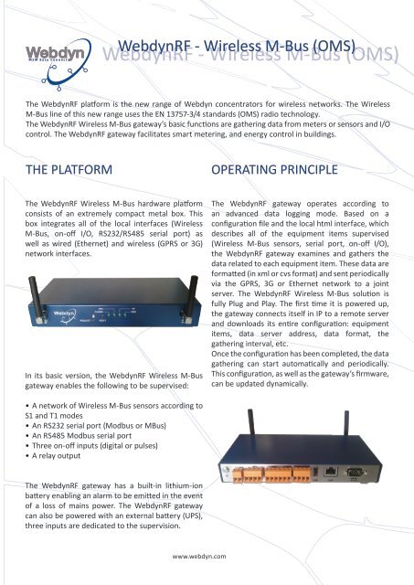
The <strong>WebdynRF</strong> platform is the new range of Webdyn concentrators for wireless networks. The <strong>Wireless</strong><br />
M-<strong>Bus</strong> line of this new range uses the EN 13757-3/4 standards (<strong>OMS</strong>) radio technology.<br />
The <strong>WebdynRF</strong> <strong>Wireless</strong> M-<strong>Bus</strong> gateway’s basic functions are gathering data from meters or sensors and I/O<br />
control. The <strong>WebdynRF</strong> gateway facilitates smart metering, and energy control in buildings.<br />
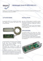
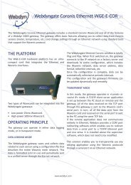
THE PLATFORM<br />
OPERATING PRINCIPLE<br />
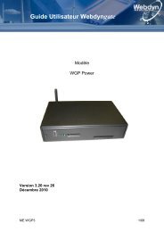
The <strong>WebdynRF</strong> <strong>Wireless</strong> M-<strong>Bus</strong> hardware platform<br />
consists of an extremely compact metal box. This<br />
box integrates all of the local interfaces (<strong>Wireless</strong><br />
M-<strong>Bus</strong>, on-off I/O, RS232/RS485 serial port) as<br />
well as wired (Ethernet) and wireless (GPRS or 3G)<br />
network interfaces.<br />
In its basic version, the <strong>WebdynRF</strong> <strong>Wireless</strong> M-<strong>Bus</strong><br />
gateway enables the following to be supervised:<br />
The <strong>WebdynRF</strong> gateway operates according to<br />
an advanced data logging mode. Based on a<br />
configuration file and the local html interface, which<br />
describes all of the equipment items supervised<br />
(<strong>Wireless</strong> M-<strong>Bus</strong> sensors, serial port, on-off I/O),<br />
the <strong>WebdynRF</strong> gateway examines and gathers the<br />
data related to each equipment item. These data are<br />
formatted (in xml or cvs format) and sent periodically<br />
via the GPRS, 3G or Ethernet network to a joint<br />
server. The <strong>WebdynRF</strong> <strong>Wireless</strong> M-<strong>Bus</strong> solution is<br />
fully Plug and Play. The first time it is powered up,<br />
the gateway connects itself in IP to a remote server<br />
and downloads its entire configuration: equipment<br />
items, data server address, data format, the<br />
gathering interval, etc.<br />
Once the configuration has been completed, the data<br />
gathering can start automatically and periodically.<br />
This configuration, as well as the gateway’s firmware,<br />
can be updated dynamically.<br />
• A network of <strong>Wireless</strong> M-<strong>Bus</strong> sensors according to<br />
S1 and T1 modes<br />
• An RS232 serial port (Modbus or M<strong>Bus</strong>)<br />
• An RS485 Modbus serial port<br />
• Three on-off inputs (digital or pulses)<br />
• A relay output<br />
The <strong>WebdynRF</strong> gateway has a built-in lithium-ion<br />
battery enabling an alarm to be emitted in the event<br />
of a loss of mains power. The <strong>WebdynRF</strong> gateway<br />
can also be powered with an external battery (UPS),<br />
three inputs are dedicated to the supervision.<br />
www.webdyn.com
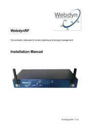
ARCHITECTURE<br />
Wirelless M-<strong>Bus</strong><br />
meters<br />
<strong>Wireless</strong> M-<strong>Bus</strong><br />
Ethernet<br />
3G<br />
GPRS<br />
Server<br />
User<br />
Pulse meters<br />
Pulses<br />
RS485<br />
RS232<br />
<strong>WebdynRF</strong> <strong>Wireless</strong> M-<strong>Bus</strong><br />
Modbus or M<strong>Bus</strong><br />
equipements<br />
I/O<br />
Circuit breakers,<br />
relays<br />
TECHNICAL CHARACTERISTICS<br />
Radio interface<br />
<strong>Wireless</strong> M-<strong>Bus</strong><br />
I/O interface<br />
Digital inputs<br />
Digital outputs<br />
Serial interface<br />
Port 1<br />
Port 2<br />
Network interface<br />
Ethernet<br />
GSM/GPRS<br />
3G<br />
General characteristics<br />
Power supply<br />
Internal battery<br />
External battery<br />
Temperatures<br />
Dimensions<br />
RTTE authorisations<br />
Characteristics<br />
Frequency bands:<br />
868,3 and 868,95 MHz<br />
3 inputs<br />
1 outputs<br />
RS485<br />
RS232<br />
10/100Mbits/s<br />
850/900/1800/1900 MHz<br />
900/2100 MHz<br />
Protocol<br />
Operating mode S1 et T1<br />
EN 13757-4 protocol<br />
On-Off - Pulses<br />
Relay<br />
Modbus<br />
Modbus/M<strong>Bus</strong><br />
IP services<br />
IP services<br />
IP services<br />
Connectors<br />
Antenna - SMA<br />
Screw terminal<br />
Screw terminal<br />
Screw terminal<br />
DB9<br />
RJ45<br />
Antenna - SMA<br />
Antenna - SMA<br />
[+12/24V] DC provided by an external power supply (Accessory)<br />
Li-Ion 650mAH<br />
Management of one external UPS per three dedicated on-off inputs<br />
Operating temperatures: -20°C to +70°C Storage temperatures: -20°C to +85°C<br />
20cm (L) x 12cm (D) x 3,2cm (H)<br />
1995/5/EEC<br />
REFERENCES<br />
Products<br />
WG0607-A01<br />
WG0607-A02<br />
Accessories<br />
AC0102-02<br />
AC0103-00<br />
AC0201-01<br />
AC0201-02<br />
AC0301-01<br />
2G modem - <strong>Wireless</strong> M-<strong>Bus</strong><br />
3G modem - <strong>Wireless</strong> M-<strong>Bus</strong><br />
DIN 12V external power supply unit<br />
24V DIN Rail power supply<br />
GPRS two-band remote antenna with 5m of cable<br />
GPRS two-band remote antenna with 20m of cable<br />
DIN Rail and wall-mounting fastening kit<br />
CONTACT<br />
26 rue des Gaudines<br />
78100 Saint-Germain-en-Laye - FRANCE<br />
T +33 1 39 04 29 40<br />
F +33 1 39 04 29 41<br />
contact@webdyn.com<br />
www.webdyn.com