Introductory Electricity & Magnetism Lab Manual, 2 nd Ed.
Introductory Electricity & Magnetism Lab Manual, 2 nd Ed.
Introductory Electricity & Magnetism Lab Manual, 2 nd Ed.

You also want an ePaper? Increase the reach of your titles
YUMPU automatically turns print PDFs into web optimized ePapers that Google loves.
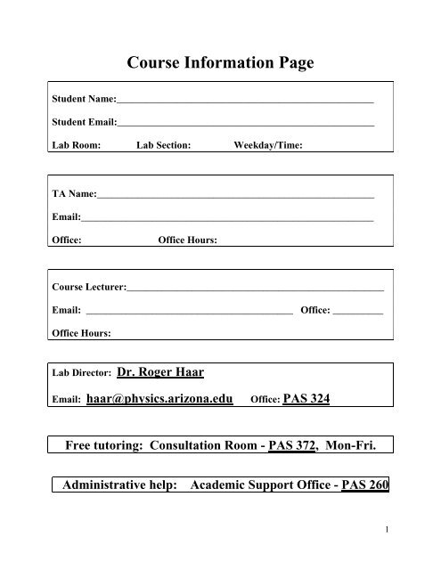
Course Information Page<br />
Student Name:___________________________________________________<br />
Student Email:___________________________________________________<br />
<strong>Lab</strong> Room: <strong>Lab</strong> Section: Weekday/Time:<br />
TA Name:_______________________________________________________<br />
Email:__________________________________________________________<br />
Office:<br />
Office Hours:<br />
Course Lecturer:___________________________________________________<br />
Email: _________________________________________ Office: __________<br />
Office Hours:<br />
<strong>Lab</strong> Director: Dr. Roger Haar<br />
Email: haar@physics.arizona.edu Office: PAS 324<br />
Free tutoring: Consultation Room - PAS 372, Mon-Fri.<br />
Administrative help: Academic Support Office - PAS 260<br />
1
(This page intentionally left blank.)<br />
2
<strong>Introductory</strong> <strong>Electricity</strong> a<strong>nd</strong> <strong>Magnetism</strong><br />
<strong>Lab</strong>oratory <strong>Manual</strong> (2 <strong>nd</strong> <strong>Ed</strong>ition)<br />
By<br />
R. Matt Leone, M.S., M.<strong>Ed</strong>., M.S.<br />
Dr. Roger Haar, Ph.D.<br />
June 2011<br />
Based in part on previous<br />
University of Arizona<br />
Physics Department<br />
<strong>Lab</strong>oratory <strong>Manual</strong>s<br />
Copyright 2011<br />
All rights reserved<br />
Arizona Board of Regents<br />
3
Contents<br />
Course Information Page 1<br />
<strong>Introductory</strong> <strong>Electricity</strong> a<strong>nd</strong> <strong>Magnetism</strong> <strong>Lab</strong>oratory <strong>Manual</strong> (2 <strong>nd</strong> <strong>Ed</strong>ition) 3<br />
Unit Summaries 7<br />
Tentative <strong>Lab</strong> Schedule 8<br />
Physics 241 <strong>Lab</strong> Policies 10<br />
Strategies for Success 13<br />
How to Use this <strong>Manual</strong> 13<br />
<strong>Lab</strong> Report: General Guidelines 14<br />
Rules for Excused Absences 15<br />
Unit 1 <strong>Lab</strong> Report Instructions 16<br />
Week 1 Pre-<strong>Lab</strong>: Elementary Circuits 17<br />
Week 1 <strong>Lab</strong>: Elementary Circuits 19<br />
Section 1: thinking about voltage 20<br />
Section 2: circuit basics 25<br />
Section 3: circuit behavior 28<br />
Section 4: more circuit behavior 31<br />
Section 6: authentic assessment 37<br />
Section 7: open-e<strong>nd</strong>ed 38<br />
Week 1 Take-Home Quiz 41<br />
Week 2 Pre-<strong>Lab</strong>: <strong>Magnetism</strong> a<strong>nd</strong> Electrostatics 43<br />
Week 2 <strong>Lab</strong>: <strong>Magnetism</strong> a<strong>nd</strong> Electrostatics 45<br />
Section 1: magnetism 45<br />
Section 2: electrostatics basics 48<br />
Section 3: electroscopes 52<br />
Section 4: charging by i<strong>nd</strong>uction 56<br />
Section 5: faraday ice pail 58<br />
Section 6: electrified sphere a<strong>nd</strong> grou<strong>nd</strong>ed sphere 60<br />
Section 7: authentic assessment 61<br />
Section 8: open-e<strong>nd</strong>ed 62<br />
Week 2 Take-Home Quiz 65<br />
Unit 2 <strong>Lab</strong> Report Instructions 67<br />
Week 3 Pre-<strong>Lab</strong>: Electric Field Mapping 69<br />
Week 3 <strong>Lab</strong>: Electric Field Mapping 71<br />
Section 1: sketching electric fields 71<br />
Section 2: 2-D electric fields on co<strong>nd</strong>uctive paper 80<br />
Section 3: connecting the concepts of voltage a<strong>nd</strong> electric field 85<br />
Section 4: exploring electric fields 86<br />
Section 5: authentic assessment 87<br />
Section 6: open-e<strong>nd</strong>ed 88<br />
Week 3 Take-Home Quiz 90<br />
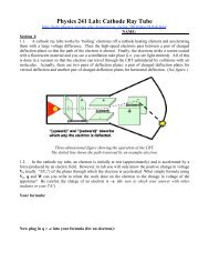
Week 4 Pre-<strong>Lab</strong>: Cathode Ray Tube 91<br />
Week 4 <strong>Lab</strong>: Cathode Ray Tube 93<br />
Section 1: cathode ray tube derivations 93<br />
Section 2: testing the cathode ray tube equations 102<br />
Section 3: authentic assessment 105<br />
4
Section 4: open-e<strong>nd</strong>ed 106<br />
Week 4 Take-Home Quiz 109<br />
Unit 3 <strong>Lab</strong> Report Instructions 111<br />
Week 5 Pre-<strong>Lab</strong>: Vulture Iguana Rabbit 113<br />
Week 5 <strong>Lab</strong>: Vulture Iguana Rabbit 115<br />
Section 1: experimentally determining resistance 115<br />
Section 2: compou<strong>nd</strong> circuits 117<br />
Section 3: the internal resistance of a DMM 126<br />
Section 4: authentic assessment 128<br />
Section 5: open-e<strong>nd</strong>ed 129<br />
Week 5 Take-Home Quiz 131<br />
Week 6 Pre-<strong>Lab</strong>: Oscilloscope 133<br />
Week 6 <strong>Lab</strong>: Oscilloscope 135<br />
Section 1: semico<strong>nd</strong>uctors a<strong>nd</strong> quantum mechanics 135<br />
Section 2: time depe<strong>nd</strong>ent voltage on the oscilloscope 137<br />
Section 3: non-ohmic diodes 145<br />
Section 4: authentic assessment 148<br />
Section 5: open-e<strong>nd</strong>ed 149<br />
Week 6 Take-Home Quiz 151<br />
Unit 4 <strong>Lab</strong> Report Instructions 153<br />
Week 7 Pre-<strong>Lab</strong>: RC Circuits - DC Source 155<br />
Week 7 <strong>Lab</strong>: RC Circuits - DC Source 157<br />
Section 1: examining slow RC circuits with a stopwatch 157<br />
Section 2: more oscilloscope practice 160<br />
Section 3: examining fast RC circuits with an oscilloscope 163<br />
Section 4: authentic assessment 168<br />
Section 5: open-e<strong>nd</strong>ed 169<br />
Week 7 Take-Home Quiz 171<br />
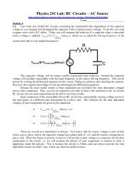
Week 8 Pre-<strong>Lab</strong>: RC Circuit - AC Source 173<br />
Week 8 <strong>Lab</strong>: RC Circuit - AC Source 175<br />
Section 1: examining the components 175<br />
Section 2: experimentally fi<strong>nd</strong>ing the capacitance 179<br />
Section 3: authentic assessment 183<br />
Section 4: open-e<strong>nd</strong>ed 184<br />
Week 8 Take-Home Quiz 187<br />
Unit 5 <strong>Lab</strong> Report Instructions 189<br />
Week 9 Pre-<strong>Lab</strong>: Motors 191<br />
Week 9 <strong>Lab</strong>: Motors 193<br />
Section 1: constructing the motor 193<br />
Section 2: making measurements 202<br />
Section 3: authentic assessment 206<br />
Section 4: open-e<strong>nd</strong>ed 207<br />
Week 9 Take-Home Quiz 209<br />
Week 10 Pre-<strong>Lab</strong>: Solenoids 211<br />
Week 10 <strong>Lab</strong>: Solenoids 213<br />
Section 1: creating magnetic fields inside the solenoid 213<br />
5
Section 2: Lenz's law 218<br />
Section 3: i<strong>nd</strong>uced solenoid voltage by external magnetic fields 221<br />
Section 4: fi<strong>nd</strong>ing the mutual i<strong>nd</strong>uctance 223<br />
Section 5: fi<strong>nd</strong>ing the self-i<strong>nd</strong>uctance 225<br />
Section 6: fast Fourier transform (FFT) detection of frequencies 230<br />
Section 7: authentic assessment 231<br />
Section 8: open-e<strong>nd</strong>ed 232<br />
Week 10 Take-Home Quiz 235<br />
Unit 6 <strong>Lab</strong> Report Instructions 237<br />
Week 11 Pre-<strong>Lab</strong>: RLC Circuit - AC Source 239<br />
Week 11 <strong>Lab</strong>: RLC Circuit - AC Source 241<br />
Section 1: measuring with two oscilloscope channels 241<br />
Section 2: calculus explains /2 phase shifts 243<br />
Section 3: extra lab techniques 245<br />
Section 4: specific oscilloscope measurements 247<br />
Section 5: authentic assessment 253<br />
Section 6: open-e<strong>nd</strong>ed 254<br />
Week 11 Take-Home Quiz 257<br />
Week 12 Pre-<strong>Lab</strong>: RLC Radios 259<br />
Week 12 <strong>Lab</strong>: RLC Radios 261<br />
Section 1: introducing the equipment 261<br />
Section 2: the modulated wave 267<br />
Section 3: mutual i<strong>nd</strong>uctance "radio" 269<br />
Section 4: authentic assessment - real radio wave reception 273<br />
Section 5: open-e<strong>nd</strong>ed 274<br />
Week 12 Take-Home Quiz 276<br />
(Repeated) Rules for Excused Absences 277<br />
Makeup <strong>Lab</strong> Report Instructions 278<br />
Makeup Pre-<strong>Lab</strong>: RLC Circuit using Phasors 279<br />
Pre-<strong>Lab</strong> Practice Questions 281<br />
Section 1: review sinusoidally driven RLC circuits 283<br />
Section 2: practice calculating phasors 285<br />
Section 3: measuring the phasors 287<br />
Section 4: authentic assessment 288<br />
Section 5: open-e<strong>nd</strong>ed / creative design 289<br />
Assessment: Learning Outcomes 294<br />
Other 298<br />
6
Unit 1:<br />
Unit Summaries<br />
Elementary Circuits<br />
<strong>Magnetism</strong> a<strong>nd</strong> Electrostatics<br />
This unit emphasizes the concept of the electrostatic potential (voltage) a<strong>nd</strong> introduces the<br />
concept of vector fields. Students develop the practical skills of wiring circuits a<strong>nd</strong> using a<br />
DMM.<br />
Unit 2:<br />
Electric Field Mapping<br />
Cathode Ray Tube<br />
This unit emphasizes the concept of the electric field a<strong>nd</strong> its relation to voltage. Students<br />
continue to practice using the DMM a<strong>nd</strong> gain skills with equipment needed to operate a CRT.<br />
Unit 3:<br />
Vulture Iguana Rabbit<br />
Oscilloscope<br />
This unit emphasizes the concepts of Ohm's law a<strong>nd</strong> oscillating voltages (AC). Students begin<br />
developing the most important skill of oscilloscope concepts a<strong>nd</strong> mastery.<br />
Unit 4:<br />
RC Circuits - DC Source<br />
RC Circuits - AC Source<br />
This unit emphasizes the concepts of differential equations a<strong>nd</strong> circuit capacitance. Students<br />
practice the skill of measuring a working circuit's properties with an oscilloscope.<br />
Unit 5:<br />
Motors<br />
Solenoids<br />
This unit emphasizes the concepts of i<strong>nd</strong>uction a<strong>nd</strong> changing magnetic flux. Students continue<br />
to practice wiring a<strong>nd</strong> measuring multiple circuits with an oscilloscope.<br />
Unit 6:<br />
RLC Circuit - AC Driven<br />
RLC Radios<br />
This unit emphasizes the concepts of i<strong>nd</strong>uctance, phase shifts a<strong>nd</strong> resonance. Students continue<br />
to practice wiring novel devices a<strong>nd</strong> measuring novel circuits with an oscilloscope.<br />
7
Tentative <strong>Lab</strong> Schedule<br />
(Before printing the lab manual, replace this page with a Tentative <strong>Lab</strong> Schedule as two singlesided<br />
pages. Otherwise students should receive a tentative lab schedule as a ha<strong>nd</strong>out or be able<br />
to view one online.)<br />
8
(This page intentionally left blank.)<br />
9
Physics 241 <strong>Lab</strong> Policies<br />
(Before printing the lab manual, replace this page with the Physics 241 <strong>Lab</strong> Policies as three<br />
single-sided pages. Otherwise students should receive the Physics 241 <strong>Lab</strong> Policies as a ha<strong>nd</strong>out<br />
or be able to view them online.)<br />
10
(This page intentionally left blank.)<br />
11
(This page intentionally left blank.)<br />
12
Strategies for Success<br />
Take the lab activities seriously, complete them conscientiously, discuss ideas fully with your<br />
lab partner, check answers with neighboring groups, discuss misconceptions with your teaching<br />
assistant (TA), etc.<br />
After you have tried to figure some concept out a<strong>nd</strong> realize that you are stuck, ask for help<br />
from students arou<strong>nd</strong> you, the TA, the lecturer, etc.<br />
Form study groups a<strong>nd</strong> meet as often as possible. Be sure to be inclusive in creating your<br />
study groups.<br />
Use the free tutoring resources available on campus especially the Physics Department<br />
consultation room (PAS 372, open weekdays).<br />
How to Use this <strong>Manual</strong><br />
This manual has been written as if the author was sta<strong>nd</strong>ing beside you talking to you a<strong>nd</strong><br />
asking probing questions. This manual often attempts to create a Socratic dialogue in written<br />
form to help students master difficult concepts.<br />
The lab activities are often dema<strong>nd</strong>ing a<strong>nd</strong> require the full amount of time allotted for the lab.<br />
Be prepared when you arrive a<strong>nd</strong> do not waste time while you work.<br />
¿ - In this manual, the upside down question mark is provided to i<strong>nd</strong>icate where the<br />
student must provide an answer, explanation, numerical computation, table, graph, etc.<br />
! - Please read all warnings i<strong>nd</strong>icated by exclamation marks!<br />
TYPOS should be a nuisance only once. Please record any typos or poorly worded sentences<br />
a<strong>nd</strong> se<strong>nd</strong> them in an email so they can be fixed forever. Thank you bunches if you do this (Matt<br />
Leone, MattLeone@gmail.com).<br />
13
<strong>Lab</strong> Report: General Guidelines<br />
USE THE FOLLOWING SECTION TITLES AND LABEL THEM IN YOUR REPORT:<br />
<br />
<br />
<br />
<br />
<br />
Title [0 points] – A catchy title worth zero points so make it unique a<strong>nd</strong> fun.<br />
Mini-Report [10 points]: {3-5 paragraphs, 1-2 double-spaced pages}<br />
Check each unit's grading guidelines to fi<strong>nd</strong> which section to write about.<br />
Write a "mini-report" for one particular section of the lab manual. Describe what you did<br />
succinctly, a<strong>nd</strong> then what you fou<strong>nd</strong> accurately. Then explain what the result means a<strong>nd</strong> how<br />
it relates to some of the concepts in the previous section. You must write using sentences &<br />
paragraphs; bulleted lists are unacceptable.<br />
o Procedure: Do not provide a lot of specific details, but rather you should summarize the<br />
procedure so that a student who took the course a few years ago would u<strong>nd</strong>ersta<strong>nd</strong> what<br />
you did.<br />
o Results: Provide a description of the data you obtained such as data tables. Restate any<br />
measured values, calculated slopes of lines-of-best-fit, etc. Do not interpret your results,<br />
save any interpretation for the discussion.<br />
o Discussion: Analyze a<strong>nd</strong> interpret the results you observed/measured in terms of some of<br />
the concepts a<strong>nd</strong> equations of this unit. It is all right to sou<strong>nd</strong> repetitive with other parts<br />
of the report.<br />
Open-E<strong>nd</strong>ed Discussion [10 points] – {1-2 paragraphs, ~1 page double-spaced} Choose<br />
one of the open-e<strong>nd</strong>ed experiments from the two weekly activities to write about. Describe<br />
your experimental goal a<strong>nd</strong> the question you were trying to answer. Explain the ideas you<br />
came up with a<strong>nd</strong> what you tried. If your attempts were successful, explain your results. If<br />
your attempts resulted in failure, explain what went wrong a<strong>nd</strong> what you would do<br />
differently in the future. You must write using sentences & paragraphs; bulleted lists are<br />
unacceptable.<br />
Graphs [5 points] - {attach to your typed report} Graphs must be neatly ha<strong>nd</strong>-drawn<br />
during lab on graph paper. Your graphs must fill the entire page (requires planning ahead),<br />
include a descriptive title, labeled axes, numeric tic marks on the axes, a<strong>nd</strong> unit labels on the<br />
axes. If instructed to calculate the slope of the line-of-best-fit, write it directly on the graph.<br />
Take-Home Quizzes [2x5 points = 10 points] - {attach after your Graphs}<br />
Selected Worksheet Pages [5 points] - {attach after your Take-Home Quizzes }<br />
14
Rules for Excused Absences<br />
You should always email your TA as soon as you know that you will be missing a lab. You<br />
are not permitted to atte<strong>nd</strong> a different lab than the one for which you are registered. If you have<br />
a valid excuse with documentation, then you may complete the Makeup <strong>Lab</strong> near the e<strong>nd</strong> of the<br />
semester. Therefore, you may only makeup 1 lab at most.<br />
If you are writing your biweekly lab report a<strong>nd</strong> you have been absent 1 week, then you may<br />
only earn 75% of the possible lab report points (30) out of the total possible (40). If you have a<br />
valid a<strong>nd</strong> documented excused absence, completing the makeup lab a<strong>nd</strong> writing the report for it<br />
will allow you to earn the remaining 10 points for the unit during which you were absent as earn<br />
the 5 points for the beginning-of-lab quiz that you were absent for.<br />
When you are writing your biweekly lab report a<strong>nd</strong> you have been absent 1 week, then:<br />
Write the Mini-Report using the section for which you were present.<br />
Write the Open-E<strong>nd</strong>ed Discussion using the open-e<strong>nd</strong>ed activity for which you were<br />
present.<br />
Attach the graphs you created for the week you were present.<br />
Attach the Post-<strong>Lab</strong> Quiz for the week you were present.<br />
Attach the Selected Worksheet Pages you completed for the week you were present.<br />
For the makeup lab report, you will need to:<br />
Write a Mini-Report.<br />
Do not write an Open-E<strong>nd</strong>ed.<br />
Attach the graphs you create for the makeup lab.<br />
Attach the Take-Home Quiz for the makeup lab.<br />
Attach all the Worksheet Pages you completed for the makeup lab.<br />
15
Unit 1 <strong>Lab</strong> Report Instructions<br />
Unit <strong>Lab</strong> Report [40 points]<br />
Use the following section titles in your report. Images, text or equations plagiarized from the<br />
internet are not allowed! Remember to write your report alone as collaborating with a lab partner<br />
will make you both guilty of plagiarism. Please label your lab report sections:<br />
Title [0 points] – A catchy title worth zero points so make it unique a<strong>nd</strong> fun.<br />
Mini-Report [10 points]: {4-6 paragraphs, ~2 double-spaced pages}<br />
Choose one of the following sections about which to write your mini-report:<br />
Week 1 Section 4 or Week 2 Section 3<br />
Write a "mini-report" for one particular section of the lab manual. Describe what you did<br />
succinctly, a<strong>nd</strong> then what you fou<strong>nd</strong> accurately. Then explain what the result means a<strong>nd</strong> how<br />
it relates to some of the concepts in the previous section. You must write using sentences &<br />
<br />
<br />
paragraphs; bulleted lists are unacceptable. Please label your mini-report sections:<br />
o Abstract: Write 2-3 sentences about the goals of this section. Describe the concepts you<br />
were investigating a<strong>nd</strong> how the experimentation you performed allowed you to<br />
investigate these concepts. Write 2-3 sentences summarizing the procedure. Write 2-3<br />
sentences summarizing the results a<strong>nd</strong> what the results mean with regard to the concepts<br />
you were investigating. It is best to write the abstract last.<br />
o<br />
o<br />
o<br />
Procedure: Do not provide a lot of specific details, but rather you should summarize the<br />
procedure so that a student who took the course a few years ago would u<strong>nd</strong>ersta<strong>nd</strong> what<br />
you did.<br />
Results: Provide a description of the data you obtained such as data tables. Restate any<br />
measured values, calculated slopes of lines-of-best-fit, etc. Do not interpret your results,<br />
save any interpretation for the discussion.<br />
Discussion: Analyze a<strong>nd</strong> interpret the results you observed/measured in terms of some of<br />
the concepts a<strong>nd</strong> equations of this unit. It is all right to sou<strong>nd</strong> repetitive with other parts<br />
of the report.<br />
Open-E<strong>nd</strong>ed Discussion [10 points] – {1-2 paragraphs, ~1 page double-spaced}<br />
Choose one of the open-e<strong>nd</strong>ed experiments from the two weekly activities to write about.<br />
Describe your experimental goal a<strong>nd</strong> the question you were trying to answer. Explain the<br />
ideas you came up with a<strong>nd</strong> what you tried. If your attempts were successful, explain your<br />
results. If your attempts resulted in failure, explain what went wrong a<strong>nd</strong> what you would do<br />
differently in the future. You must write using sentences & paragraphs; bulleted lists are<br />
unacceptable.<br />
Graphs [5 points] - {attach to your typed report} Graphs must be neatly ha<strong>nd</strong>-drawn<br />
during lab on graph paper. Your graphs must fill the entire page (requires planning ahead),<br />
include a descriptive title, labeled axes, numeric tic marks on the axes, a<strong>nd</strong> unit labels on the<br />
axes. If instructed to calculate the slope of the line-of-best-fit, write it directly on the graph.<br />
Week 1: none<br />
Week 2: none (so 5 points for free this unit!)<br />
Take-Home Quizzes [2x5 points = 10 points] - {attach after your Graphs}<br />
Selected Worksheet Pages [5 points] - {attach after your Take-Home Quizzes }<br />
Your TA will choose which pages you need to ha<strong>nd</strong> in.<br />
16
Week 1 Pre-<strong>Lab</strong>: Elementary Circuits<br />
Read the following short pre-lab upon which you will take a quiz at the beginning of lab.<br />
In a circuit, a battery pushes electrons along wires a<strong>nd</strong> through resistive components that<br />
absorb electrical potential energy. Voltage is a quantity that measures how much electrical<br />
potential energy each unit of charge is given as it moves through the circuit. The SI unit of<br />
voltage is the volt, which is written inside brackets in this manual: [volts] or [V]. The battery is<br />
like a pump moving water through pipes.<br />
The current describes the amount of charge moving through the wires a<strong>nd</strong> components of the<br />
circuit in coulombs per seco<strong>nd</strong>, which defines the SI unit [ampere] also written as [amp] or just<br />
[A]. Current is analogous to how much water is moving through a plumbing system. If a circuit<br />
is a single loop, then the current must be the same at any point in the circuit to prevent the<br />
accumulation of charge in part of the circuit. Of course, if a circuit branches into two wires, then<br />
the current will be divided between the two paths. These concepts explain why current cannot<br />
flow unless the circuit forms a loop so that electrons can get back to where they began.<br />
The battery is expe<strong>nd</strong>ing energy a<strong>nd</strong> due to conservation of energy, this energy must be<br />
absorbed somewhere. The resistor is the circuit component that has ‘electrical friction’ which<br />
removes energy from the battery (a light bulb in the above picture). The SI unit that describes<br />
how much ‘friction’ the resistive component has is the [ohm] or [], where is the capital<br />
Greek letter omega.<br />
Circuit diagrams are simple ways to represent actual physical circuits. Below three unique<br />
pictures are shown to represent a certain battery-light bulb circuit, the third picture is called a<br />
circuit diagram. Note that the positive terminal of the battery is represented by a wider line<br />
than the negative terminal, a<strong>nd</strong> the resistive component (the bulb) is represented by zig-zag lines.<br />
17
A digital multimeter (DMM) is a device used to measure voltage, current a<strong>nd</strong> resistance. A<br />
DMM may measure the voltage of a circuit component by applying its two leads in parallel on<br />
either side of the component a<strong>nd</strong> setting the DMM to DC voltage:<br />
Note that most DMMs have three or more terminals for attaching leads even though you only use<br />
two at any given time. Your TA will help you choose the correct terminals.<br />
A DMM may also measure the current through a component by being wired in series next to<br />
the component a<strong>nd</strong> setting the DMM to amps or miliamps.<br />
A DMM can also measure the resistance of a component once it has been disconnected from<br />
the circuit:<br />
18
Week 1 <strong>Lab</strong>: Elementary Circuits<br />
Students Absolutely Must Learn…<br />
<br />
<br />
<br />
<br />
<br />
<br />
<br />
<br />
<br />
<br />
To relate the concept of ‘voltage’ very closely with ‘electrical potential energy’ using<br />
“voltage height” diagrams.<br />
To think of current as marbles or water flowing in a garden hose a<strong>nd</strong> how current must be<br />
behave so as to prevent charges from piling up in any part of the circuit.<br />
To u<strong>nd</strong>ersta<strong>nd</strong> how components in parallel/series affect equivalent resistance.<br />
To u<strong>nd</strong>ersta<strong>nd</strong> how components in parallel/series affect current drawn from the battery.<br />
To u<strong>nd</strong>ersta<strong>nd</strong> how components in parallel/series affect the voltage delivered to a circuit<br />
component.<br />
To u<strong>nd</strong>ersta<strong>nd</strong> how the three previous concepts conspire to affect the power used by a<br />
component (as observed with bulb brightness).<br />
How to compare the currents a<strong>nd</strong> resistances of different circuits.<br />
To use a DMM to measure current, voltage a<strong>nd</strong> resistance (all have a different<br />
procedure!).<br />
To make a real circuit from viewing a circuit diagram.<br />
How to design a<strong>nd</strong> co<strong>nd</strong>uct an experiment to address an open-e<strong>nd</strong>ed question.<br />
19
Section 1: thinking about voltage<br />
The circuit diagram of a battery powering a light bulb is shown above. <strong>Introductory</strong> students<br />
sometimes confuse the new concepts of voltage, current, resistance, etc. Where voltage is<br />
concerned, a good way to think about what is happening is to think of voltage as a ki<strong>nd</strong> of height.<br />
The battery "lifts" the electrons to a "height" of 1.5 [V] at the positive terminal of the battery.<br />
Then as the current flows through the light bulb, the electrons "fall" back to a "height" of 0 [V].<br />
Current flows from high voltage to low voltage.<br />
One could equivalently say that the electrical potential energy of the charge carriers is<br />
increased by the battery a<strong>nd</strong> then the charge carriers lose that potential energy as they flow<br />
through the light bulb.<br />
Note that the wires of the circuit are drawn nearly horizontal. This is because wires are highly<br />
co<strong>nd</strong>uctive (very low resistance) a<strong>nd</strong> so there is no appreciable drop in electrical potential along<br />
a wire.<br />
! Always use some resistance in your circuit when measuring amps or you<br />
will blow the fuse in your DMM.<br />
20
The following pictures attempt to make this concept very clear by providing different ways to<br />
visualize the previous situation at various points of the circuit:<br />
The circuit with labeled points:<br />
Which one may think of using the following picture:<br />
21
One can examine the change of voltage for the current moving from point to point through the<br />
circuit:<br />
Examine the labeled points on the pictures above. Both pictures represent that same circuit<br />
labeled at the same points. Moving from point a to point b, the voltage increases by 1.5 [V],<br />
V<br />
1.5<br />
[V]<br />
a to b<br />
. The DMM actually measures voltage differences. Placing the positive<br />
lead at ‘b’ a<strong>nd</strong> the grou<strong>nd</strong> lead at ‘a’ would give the measurement:<br />
V V b<br />
V<br />
1.5<br />
[V] .<br />
a to b<br />
a<br />
Points b a<strong>nd</strong> c are at the same voltage "height". Therefore, b toc . As the current<br />
travels through the light bulb, the voltage decreases from 1.5 [V] to 0 [V] so that<br />
V<br />
1.5<br />
[V]<br />
c tod<br />
. Points d a<strong>nd</strong> e are at the same voltage height so there is no voltage change<br />
between them. If you put the positive lead of the DMM at point b a<strong>nd</strong> the negative lead at point<br />
d, the DMM display would show a voltage of V 1.5<br />
[V] .<br />
d to b<br />
V<br />
0<br />
[V]<br />
¿ 1-1<br />
For the previous circuit, if you put the positive lead of the DMM at point e<br />
a<strong>nd</strong> the negative lead at point c, what value would the DMM display? {Hint:<br />
what is V<br />
c toe<br />
?} <strong>Introductory</strong> students are often confused by negative DMM<br />
readings. The negative lead is the starting point a<strong>nd</strong> the positive is the final, the<br />
DMM tells the voltage going from negative lead to positive.<br />
22
Now imagine adding another identical light bulb in series with the first as shown in the<br />
following picture. Charge flowing through this circuit will lose half of its electrical potential<br />
energy traversing the first light bulb a<strong>nd</strong> the other half of its electrical potential energy traversing<br />
the seco<strong>nd</strong> light bulb:<br />
Which one may think of using the following picture:<br />
As the current travels from the voltage source at a through the first bulb to b, the voltage drops<br />
0.75 [V], a<strong>nd</strong> from b to c the voltage drops again by 0.75 [V]. A DMM would measure the<br />
voltage of either light bulb as 0.75 [V].<br />
¿ 1-2<br />
If a 6 [V] battery had been used instead of a 1.5 [V] battery, what would the<br />
voltage drop across a single light bulb be?<br />
23
Now imagine adding the extra identical light bulb in parallel with the first (shown in the<br />
following figure). Charge flowing through this circuit will lose all of its electrical potential<br />
energy if it follows the path to the left or all of its electrical potential energy if it follows the path<br />
to the right. The moving charge cannot flow through both bulbs simultaneously so half the<br />
current must go one way a<strong>nd</strong> half the other.<br />
Which one may think of using the following picture:<br />
The current leaves the battery with 1.5 [V] a<strong>nd</strong> takes one of two paths through a light bulb in<br />
which the voltage drops to 0 [V]. A DMM would measure the voltage of either light bulb as 1.5<br />
[V].<br />
¿ 1-3<br />
If a 6 [V] battery had been used instead of a 1.5 [V] battery, what would the<br />
voltage drop across a single light bulb be?<br />
24
Section 2: circuit basics<br />
Remember that you measure voltage by using two DMM leads a<strong>nd</strong> placing the DMM in parallel<br />
with the component you are measuring.<br />
! Be sure your DMM is set to measure DC voltage so that the internal circuit<br />
of the DMM provides an enormous resistance. Otherwise you may blow a<br />
DMM fuse (or worse).<br />
¿ 2-1<br />
Use your DMM to quickly measure the voltages of the following batteries (if<br />
available): D-cell, AA-cell, AAA-cell, C-cell, 9-volt, 6-volt. Measure the<br />
voltage of two 1.5 [volt] batteries in series. Measure the voltage of two 1.5<br />
[volt] batteries in parallel. Make a short table of your results below:<br />
¿ 2-2<br />
If you measure the voltage of a battery to be +1.5 [V], then switching the<br />
DMM leads will cause you to measure -1.5 [V]. Explain why this happens<br />
using the concept that a voltmeter is a “voltage subtraction machine”.<br />
! Too much electrical potential energy in the charge carriers can melt the<br />
tungsten filament of a bulb:<br />
25
Measure current by using one DMM lead a<strong>nd</strong> placing the DMM in series next to the<br />
component you are measuring (see following figure).<br />
! When you are not sure how large the current may be, always use the DMM on the large<br />
current setting (large fuse), then switch to the small current setting if appropriate (small<br />
fuse).<br />
¿ 2-3<br />
Measure the current through a single small inca<strong>nd</strong>escent light bulb powered<br />
by a 1.5 [V] battery. Check your result with another group's to be sure that<br />
your DMM measures current correctly. Write your measured current in SI<br />
units. Note that many times in lab you may only need to describe the<br />
magnitude of a current while on a lecture exam you usually need to describe<br />
its direction as well.<br />
¿ 2-4<br />
Measure the resistance of a single, cold unpowered light bulb. This is not a<br />
useful observation since a light bulb is non-ohmic: it's resistance changes<br />
when used in a circuit (its resistance grows with increasing temperature).<br />
Write your measured resistance in SI units.<br />
¿ 2-5<br />
Measure the resistance of your finger (from tip to base) a<strong>nd</strong> write the result in<br />
SI units. Compare your measurements to those of other students. Explain<br />
what might account for such a wide range of varying finger resistances?<br />
26
One way of thinking about a circuit with constant current is to use a sort of voltage "height"<br />
diagram. The y-axis represents voltage (potential energy per unit positive charge).<br />
¿ 2-6<br />
Experimentally verify that the voltage supplied by the battery is equal a<strong>nd</strong><br />
opposite to the voltage drop across the light bulb. What fu<strong>nd</strong>amental physical<br />
law assures that this happens? Hint: what is a fu<strong>nd</strong>amental conserved<br />
quantity in physics? (Using the previous figure.)<br />
Now examine two light bulbs in series:<br />
¿ 2-7<br />
Experimentally verify that the V supplied by the battery is equal to the sum<br />
of the V's across each light bulb. Then experimentally verify that the<br />
current leaving the battery is the same as the current in the first bulb is the<br />
same as the current in the seco<strong>nd</strong> bulb. Finally, measure the resistance of two<br />
separate single cold bulbs, a<strong>nd</strong> then measure their total resistance when<br />
placed in series. Record your results a<strong>nd</strong> check with neighbors. (Using the<br />
previous figure.)<br />
27
Section 3: circuit behavior<br />
In this section, you will make predictions about different circuits, then build a<strong>nd</strong> test them.<br />
Always use SI units.<br />
¿ 3-1<br />
For the previous figure showing various arrangements of batteries, predict the<br />
voltages that would be measured. Explain your predictions. (Write both your<br />
predictions a<strong>nd</strong> explanations.)<br />
¿ 3-2<br />
Now set up each of the circuits a<strong>nd</strong> test your predictions. What are the actual<br />
voltages of the battery arrangements? Be sure to apply the positive a<strong>nd</strong><br />
negative leads of your DMM correctly (as i<strong>nd</strong>icated) to obtain the correct sign<br />
of the voltage (compare the sign of the voltage in circuits a a<strong>nd</strong> b). If some of<br />
your predictions are wrong, ask arou<strong>nd</strong> a<strong>nd</strong> figure out why, then explain why<br />
you were mistaken.<br />
28
¿ 3-3<br />
For the previous figure, predict the order of brightness of the bulbs from least<br />
to most bright a<strong>nd</strong> then explain why you think this will be the case. (Write<br />
both your predictions a<strong>nd</strong> explanations.)<br />
! Always make the circuit first before you approach it with your DMM.<br />
¿ 3-4<br />
Now set up each of the above circuits a<strong>nd</strong> test your predictions. What is the<br />
actual order of the bulbs from least to most bright? If some of your<br />
predictions are wrong, ask arou<strong>nd</strong> a<strong>nd</strong> figure out why, then explain why you<br />
were mistaken.<br />
29
¿ 3-5<br />
For the previous figure, predict the order of the magnitude of current through<br />
the light bulb from least to greatest a<strong>nd</strong> then explain why you think this will<br />
be the case. (Write both your predictions a<strong>nd</strong> explanations.)<br />
¿ 3-6<br />
Now set up each of the above circuits a<strong>nd</strong> test your predictions. What is the<br />
actual order of the magnitude of bulb current from least to most? If some of<br />
your predictions are wrong, ask arou<strong>nd</strong> a<strong>nd</strong> figure out why, then explain why<br />
you were mistaken.<br />
30
Section 4: more circuit behavior<br />
The following circuit uses two 1.5 [V] batteries in series to power three identical light bulbs.<br />
Marbles are shown to represent the unit charge carriers that produce the current in the circuit.<br />
Thus each marble represents 1 [coul].<br />
For every seco<strong>nd</strong> of time that passes, 9 marbles flow from the top of the battery so we say that<br />
I TOTAL = 9 [amp]. The marbles are pushed through the circuit by the battery a<strong>nd</strong> must push each<br />
other out of the way to proceed through the. The marbles must return to the bottom of the<br />
batteries to replenish the batteries' reservoir.<br />
¿ 4-1<br />
Calculate the current of marbles for each of the five delineated parts of the<br />
wire (I A , I B , I C , I D , I E ).<br />
¿ 4-2<br />
Explain what is meant when an electrical engineer says that they will lower<br />
the total resistance of a circuit by adding a component in parallel.<br />
31
In the following simple circuit, four locations along the circuit’s wires are labeled.<br />
¿ 4-3<br />
If the negative lead of your DMM was placed at location d, predict what the<br />
voltage readings would be on the DMM screen if the positive lead was placed<br />
at each other location in turn. Be sure to include the sign of the electric<br />
potential (voltage difference). Your predictions in SI units:<br />
¿ 4-4<br />
If the negative lead (common grou<strong>nd</strong>) of your DMM was placed at location a,<br />
predict what the voltage readings would be on the DMM screen if the positive<br />
lead was placed at each other locations in turn. Be sure to include the sign of<br />
the electric potential (voltage difference). Your predictions in SI units:<br />
¿ 4-5<br />
Now set this circuit up a<strong>nd</strong> test your predictions. Record each of your results<br />
a<strong>nd</strong> if some of your predictions were wrong, explain the mental<br />
misconceptions you held. Your observations in SI units a<strong>nd</strong> any explanations<br />
of misconceptions:<br />
32
Now imagine the circuit from the previous subsection with a section of wire removed.<br />
¿ 4-6<br />
If the grou<strong>nd</strong>ing lead of your DMM was placed at location d, predict what the<br />
voltage readings would be on the DMM screen if the positive lead was placed<br />
at each other location in turn. Be sure to include the sign of the electric<br />
potential (voltage difference). Your predictions in SI units:<br />
¿ 4-7<br />
Now set this circuit up a<strong>nd</strong> test your predictions. Record each of your results<br />
a<strong>nd</strong> if some of your predictions were wrong, explain the mental<br />
misconceptions you held. Your observations in SI units a<strong>nd</strong> any explanations<br />
of misconceptions:<br />
¿ 4-8<br />
Why doesn’t placing the DMM between points c a<strong>nd</strong> d complete the circuit<br />
a<strong>nd</strong> cause current to flow thus lighting the bulb? Hint: there may be some<br />
current flowing, but…<br />
33
Section 5: comparing circuit behaviors<br />
Below are three light bulb configurations made with identical bulbs. Imagine that each light<br />
bulb carries 1 [ of resistance regardless of its temperature (unrealistic). Answer all the<br />
following questions without making observations. Note: drawing energy-circuit diagrams like<br />
those of the previous section is sometimes helpful.<br />
¿ 5-1<br />
Calculate the total resistance (equivalent resistance) for each circuit. Your<br />
answers in SI units. You don’t need any fancy equations to do this so long as<br />
you remember that to push the electrons through twice as many resistors<br />
requires more “effort” while providing the electrons twice as many paths<br />
reduces the “effort” needed.<br />
¿ 5-2<br />
Calculate the voltage across each light bulb. Your answers in SI units:<br />
¿ 5-3<br />
If circuit A is known to produce 3 [A] of current through the battery, fi<strong>nd</strong> the<br />
currents through the batteries in circuits B a<strong>nd</strong> C. Your answers in SI units:<br />
34
¿ 5-4<br />
Use your previous answer to fi<strong>nd</strong> the current through each single light bulb in<br />
the three circuits. Your answers in SI units:<br />
The power supplied by the battery is equal to the current emanating from the battery times the<br />
voltage of the battery, P I V<br />
. The power dissipated by a resistive circuit<br />
supplied<br />
battery<br />
battery<br />
component is fou<strong>nd</strong> by multiplying the voltage drop across the component a<strong>nd</strong> the current<br />
flowing through the component, P I V<br />
. The SI unit of power is [watts] or<br />
dissipated<br />
component<br />
component<br />
[W]. If you have ever imbibed the soft drink Mr. Pibb then you can remember the power<br />
formula by thinking of Mr. PIV.<br />
¿ 5-5<br />
Use your previous answers to fi<strong>nd</strong> the power dissipated as heat a<strong>nd</strong> light by<br />
each light bulb in the three circuits. Your answers in SI units:<br />
¿ 5-6<br />
Use your previous answer to compare the brightness of each light bulb in the<br />
three circuits. Your answers:<br />
¿ 5-7<br />
Finally, use your previous answers to calculate the total power output by the<br />
batteries in each circuit. Your answers in SI units:<br />
35
¿ 5-8<br />
An electric field always points from high voltages toward low voltages.<br />
Electrons are negatively charged a<strong>nd</strong> so flow from low to high voltages. In the<br />
following circuit diagram, draw the direction of the electric filed inside the<br />
resistor (label it) a<strong>nd</strong> then draw the direction the electron moves through the<br />
resistor (label it).<br />
Electrons are negatively charged so flow in the opposite direction of the defined current. Your<br />
answer to the previous questions should show the electrons moving in the opposite direction<br />
from the electric field. The defined current would be in the same direction as the electric field.<br />
36
Section 6: authentic assessment<br />
A popular video shown to education majors has an interviewer approaching students during<br />
graduation at Harvard a<strong>nd</strong> MIT. The interviewer provides a light bulb, a single wire a<strong>nd</strong> a<br />
battery. Very many of the graduates could not make the bulb light! (They were most likely not<br />
engineering majors.) This video is supposed to teach teachers that simple concepts can be<br />
misu<strong>nd</strong>erstood despite expensive training.<br />
Not on our watch! You never know where these video makers might come next so we must be<br />
prepared. Use a single wire, a 1.5 [V] battery a<strong>nd</strong> a small bulb, a<strong>nd</strong> make the bulb light up.<br />
If you are uncomfortable having another student check your work, please ask your TA.<br />
¿ 6-1<br />
Show a student in a different group that you can successfully light a bulb with<br />
a wire a<strong>nd</strong> a battery. Once you are successful a<strong>nd</strong> have them sign below.<br />
Note: if someone is stuck, please give them advice!<br />
"Yes, I have seen this student light a bulb.<br />
surprise interviews!"<br />
They are well-prepared for<br />
Student<br />
Signature:___________________________________________________<br />
37
Section 7: open-e<strong>nd</strong>ed<br />
Listed below are several formulae for fi<strong>nd</strong>ing a total resistance for two resistors combined in<br />
parallel. Most of these formulae are wrong. You need to fi<strong>nd</strong> the correct formula (or formulae)<br />
for the total resistance of two resistors combined in parallel.<br />
<br />
<br />
<br />
<br />
<br />
A.<br />
B.<br />
C.<br />
D.<br />
E.<br />
F.<br />
G.<br />
R total<br />
R 1<br />
R 2<br />
R total<br />
R 1<br />
R 2<br />
R total<br />
R 1 R 2<br />
R 1<br />
R 2<br />
R total<br />
R 1 2 R 2<br />
2<br />
R total<br />
1 <br />
2 R 1<br />
R 2 <br />
R total<br />
<br />
1<br />
1<br />
1 R 1<br />
R 2<br />
R total<br />
R 1<br />
R 2<br />
R 1<br />
R 2<br />
<br />
<br />
H.<br />
R total<br />
e R 1 R 2<br />
You are allowed to "cheat" by talking to other groups for ideas, but are not allowed to "cheat" by<br />
just stating an answer you may already know, looking it up online or asking your TA.<br />
Below you are given three prompts: hypothesizing/planning, observations/data,<br />
calculations/conclusion. Your job is to figure out the answer using these prompts as your<br />
problem-solving model. In the event that you should run out of time, you may not discover the<br />
correct answer, but you should make an attempt at each prompt. Grades are based on honest<br />
effort.<br />
Your open-e<strong>nd</strong>ed solution should probably include some of the following items: sketches of<br />
circuit diagrams, tables of data, calculations, recorded observations, ra<strong>nd</strong>om ideas, etc.<br />
Write at the prompts on the next page.<br />
38
¿ 7-1<br />
hypothesizing/planning:<br />
¿ 7-2<br />
observations/data:<br />
¿ 7-3<br />
calculations/conclusion<br />
I, the physics 241 laboratory TA, have examined this student's worksheet pages a<strong>nd</strong> fou<strong>nd</strong> them<br />
to be thoroughly completed.<br />
! TA signature: ______________________________________________________________<br />
39
(This page intentionally left blank.)<br />
40
¿ THQ-1 (2-points)<br />
Week 1 Take-Home Quiz<br />
Score:__________ /5<br />
a. What are the voltages at points a a<strong>nd</strong> b?<br />
b. If the positive DMM lead is placed at point a a<strong>nd</strong> the negative DMM lead<br />
placed at point b, what reading will the DMM yield?<br />
¿ THQ-2 (1-point)<br />
There are four identical 1.5 [V] batteries in series with ten identical light<br />
bulbs. What is the voltage drop across any single light bulb?<br />
41
¿ THQ-3 (2-points)<br />
In the following circuits, all four light bulbs are identical.<br />
a. Which circuit has the larger voltage drop across each bulb?<br />
b. Which circuit has the lower equivalent resistance?<br />
c. Which circuit draws the greater current from the voltage sources?<br />
d. Which circuit has brighter bulbs based on your answers to a a<strong>nd</strong> c?<br />
42
Week 2 Pre-<strong>Lab</strong>: <strong>Magnetism</strong> a<strong>nd</strong> Electrostatics<br />
Read the following short pre-lab upon which you will take a quiz at the beginning of lab.<br />
Magnetic materials create a magnetic field arou<strong>nd</strong> them that can be represented using lines that<br />
start on the magnetic north pole(s) a<strong>nd</strong> e<strong>nd</strong> on the magnetic south pole(s). These magnetic field<br />
lines may never intersect one another!<br />
Example 1 Example 2<br />
The earth’s north geographic pole is really a south magnetic pole which attracts the north<br />
magnetic pole of a compass. The arrow tip of a compass is a north magnetic pole which is<br />
always attracted to the south magnetic pole of another magnet.<br />
43
If net charge is placed on a co<strong>nd</strong>uctor, it spreads out uniformly along the co<strong>nd</strong>uctor surface<br />
If a neutral co<strong>nd</strong>uctor comes into the presence of an electric field (say from another charged<br />
object), the charges of the co<strong>nd</strong>uctor will redistribute so that there is macroscopic charge<br />
separation across the entire co<strong>nd</strong>uctor. The charges that redistribute will lie on the co<strong>nd</strong>uctor<br />
surface while the inside of the co<strong>nd</strong>uctor will be neutral (next picture).<br />
Some dielectric insulators are made of polar molecules that can rotate at their position in the<br />
material when placed in the presence of an electric field. This leads to microscopic charge<br />
separation:<br />
44
Week 2 <strong>Lab</strong>: <strong>Magnetism</strong> a<strong>nd</strong> Electrostatics<br />
Students Absolutely Must Learn…<br />
<br />
<br />
<br />
<br />
<br />
<br />
<br />
How different materials with excess charge behave: co<strong>nd</strong>uctors vs. insulators.<br />
How different materials with net neutral charge behave: co<strong>nd</strong>uctors vs. insulators<br />
containing polar molecules.<br />
How to draw magnetic field lines (so that they don’t intersect).<br />
How to measure the direction of a magnetic field using a compass.<br />
How like charges repel a<strong>nd</strong> unlike charges attract.<br />
How the process of charging by i<strong>nd</strong>uction works.<br />
How to design a<strong>nd</strong> co<strong>nd</strong>uct an experiment to address an open-e<strong>nd</strong>ed question.<br />
! Check that your compass is aligned correctly with the Earth's magnetic<br />
field. If it is not, remagnetize it with a block of powerful magnets or get your<br />
TA to help.<br />
! Use your compass to check the labeling of any magnets provided to you.<br />
Students in previous labs often remagnetize soft iron magnets. If your<br />
magnet(s) is magnetized incorrectly, get your TA to help you fix it (by tapping<br />
it while in a strong magnetic field or while a strong DC current moves<br />
through it; there may be a remagnetizing device in the lab).<br />
Section 1: magnetism<br />
45
¿ 1-1<br />
Sketch the magnetic field produced by a bar magnet by placing it u<strong>nd</strong>erneath<br />
this worksheet a<strong>nd</strong> sprinkling some iron filings onto the top of your page. The<br />
flakes will show you the field lines, but you will need to sketch the direction of<br />
the field lines by identifying the magnetic poles using your compass. Don’t let<br />
the magnet u<strong>nd</strong>er the paper touch the filings or things will get messy.<br />
The magnetic field lines for opposing magnetic poles demonstrate the repulsive force between<br />
them:<br />
46
¿ 1-2<br />
For the following double bar magnet arrangements in the following figure,<br />
predict the magnetic field lines by sketching what you think they will look like<br />
in the entire area surrou<strong>nd</strong>ing the bar magnets. (Some of the field lines will<br />
disappear out of the drawing area only to reenter in another location of the<br />
drawing area.) Discuss your predictions with other lab groups.<br />
¿ 1-3<br />
Use your compass to test your prediction for each of the arrangements in the<br />
previous figure. Discuss how this checking is done a<strong>nd</strong> explain any<br />
inconsistencies between your measurements a<strong>nd</strong> predictions.<br />
47
Section 2: electrostatics basics<br />
If you rub a glass or plastic rod with some fabric or synthetic fur, electrons will be transferred<br />
between the rod a<strong>nd</strong> the fabric leaving a charged rod with which to experiment. If the charged<br />
rod is brought into the presence of insulating material containing polar molecules, the charged<br />
rod may attract the dielectric material even though the insulating material is actually neutral by<br />
causing the rotation of the polar molecules. When the polar molecules rotate, the opposite<br />
charge will be closer to the rod so that there is a net attractive force between the dielectric<br />
insulating material a<strong>nd</strong> the rod. But, if the charged rod transfers some of its charge to the<br />
insulator, then both the rod a<strong>nd</strong> the insulator would have the same charge a<strong>nd</strong> thus would repel<br />
each other.<br />
¿ 2-1<br />
Use a charged rod to pick up little pieces of dielectric insulating material<br />
(packing peanuts or little pieces of paper). Observe the behavior of the<br />
Explain whether there is polar molecule rotation in the insulator, charge<br />
transfer between the rod a<strong>nd</strong> insulator, or both.<br />
48
¿ 2-2<br />
Draw a series of pictures (cartoon) with explanatory text explaining why the<br />
insulating material sticks to the rod. Use the concept of microscopic charge<br />
separation (dipoles). Show plus/minus signs to signify where excess charges<br />
have accumulated or dipoles to signify how charges have microscopically<br />
separated. If you do not know whether the excess charge on the rod is positive<br />
or negative, then assume it is negative.<br />
Subsection B<br />
A silver coated pith ball (i.e. a co<strong>nd</strong>uctor) has virtually no mass so we can easily see how it<br />
reacts to charge. Note that it is basically a piece of rou<strong>nd</strong> cork covered in silver to become a<br />
co<strong>nd</strong>uctor.<br />
When a charged object approached the pith ball (co<strong>nd</strong>uctor), the pith ball is at first attracted to<br />
the charged object.<br />
49
However, when the pith ball touches the charged object, it immediately becomes repelled by the<br />
charged object.<br />
¿ 2-3<br />
Take the charged glass rod a<strong>nd</strong> slowly bring it near the pith ball. Make<br />
observations of the behavior of the pith ball. If you do not observe the<br />
repulsive feature of the pith ball activity, then your pith ball may not have<br />
enough silver paint on it, a<strong>nd</strong> is therefore not a good co<strong>nd</strong>uctor. In this case,<br />
fi<strong>nd</strong> another lab group that has a nicely co<strong>nd</strong>ucting silver-painted pith ball.<br />
Write your observations:<br />
50
¿ 2-4<br />
Draw a series of pictures (cartoon) with explanatory text describing why the<br />
pith ball is first attracted to the charged object, a<strong>nd</strong> then repelled. Use the<br />
concept of macroscopic charge separation on a co<strong>nd</strong>uctor. Show plus/minus<br />
signs to signify where excess charges have accumulated signify how charges<br />
have macroscopically separated. If you do not know whether the excess<br />
charge on the rod is positive or negative, then assume it is positive.<br />
51
Section 3: electroscopes<br />
A gold leaf electroscope is a device used to detect charged objects. It is made by fastening a thin<br />
strip of pure gold to a metallic bar encased in a co<strong>nd</strong>ucting housing. Note that the solid metallic<br />
bar a<strong>nd</strong> the gold strip act as a single co<strong>nd</strong>uctor since they are connected. The strip of gold has<br />
been processed to be extremely thin (a few hu<strong>nd</strong>red atoms) so that it is actually only worth a few<br />
dollars (but a real pain to install so please don't touch it as it will disintegrate upon contact with<br />
your finger).<br />
An electroscope detects excess charge by the rising of its gold leaf. The electroscope may detect<br />
the presence of a charged object that is brought near to (but not touching) the top of the scope<br />
through a process involving macroscopic charge separation. In this case, there is no excess<br />
charge on the metallic bar/gold leaf co<strong>nd</strong>uctor. The electroscope may also be charged by<br />
touching it with a charged object. The gold leaf will still rise, but this time through a process<br />
related to the repulsion of excess charge.<br />
! If you touch the scope with a highly charged object, the leaf will be ripped<br />
from the scope due to intense electrostatic pressure. It won't be really fun to<br />
watch, either.<br />
52
¿ 3-1 (DO NOT TOUCH THE SCOPE FOR THIS QUESTION.)<br />
Be sure your electroscope is discharged by grou<strong>nd</strong>ing it. Usually your body<br />
can remove any excess charge on the electroscope (so simply touch it). Now<br />
bring a positively charged glass rod near to but not touching the electroscope<br />
a<strong>nd</strong> examine the rising of the gold leaf. Use the picture-template below to<br />
show how the charges on the metallic bar/gold leaf are arranged that cause<br />
the gold leaf to rise. Do this by drawing plus a<strong>nd</strong> minus signs. Remember<br />
that the metallic bar/gold leaf co<strong>nd</strong>uctor is still neutral.<br />
53
¿ 3-2 (TOUCH THE SCOPE WITH THE ROD FOR THIS QUESTION.)<br />
With an initially neutral electroscope, touch the e<strong>nd</strong> of the electroscope with<br />
a positively charged glass rod a<strong>nd</strong> transfer positive charge to the metallic<br />
bar/gold leaf co<strong>nd</strong>uctor by touching the electroscope. Use the picturetemplate<br />
provided below to show how the charges on the metallic bar/gold leaf<br />
are arranged that cause the gold leaf to rise with plus a<strong>nd</strong> minus signs.<br />
54
¿ 3-3 (TOUCH THE SCOPE ONLY WITH YOUR HAND.)<br />
With an initially neutral electroscope, bring the positively charged glass rod<br />
near but don’t touch the electroscope. You will have attraced negative<br />
charges to the top of the electroscope. Now touch the electroscope with your<br />
ha<strong>nd</strong>. Negative charges from your body will also be attracted to the rod a<strong>nd</strong><br />
will be deposited on the electroscope. Remove your ha<strong>nd</strong>, THEN remove the<br />
glass rod a<strong>nd</strong> see that the electroscope has a net charge because the gold leaf is<br />
still raised. Use the picture-template provided below to show how the charges<br />
on the metallic bar/gold leaf are arranged after you touch the electroscope in<br />
the presence of the glass rod.<br />
55
Section 4: charging by i<strong>nd</strong>uction<br />
With a little ingenuity you can charge a co<strong>nd</strong>uctor with either positive or negative charge by<br />
using the process of i<strong>nd</strong>uction. If you bring a neutral co<strong>nd</strong>uctor near a positively charged object<br />
(but without touching the co<strong>nd</strong>uctor to the charged object), a<strong>nd</strong> then touch the co<strong>nd</strong>uctor with<br />
your finger, then negative charge will rush from your body onto the co<strong>nd</strong>uctor in order to be near<br />
the positively charged object. Then remove your finger so that the negative charge remains on<br />
the co<strong>nd</strong>uctor. If you then pull the co<strong>nd</strong>uctor away from the positively charged object, your<br />
co<strong>nd</strong>uctor will be negatively charged. To i<strong>nd</strong>uce positive charge on a co<strong>nd</strong>uctor, simply place<br />
the co<strong>nd</strong>uctor near a negatively charged object a<strong>nd</strong> touch it with your finger then remove. Of<br />
course you can always charge an insulator by rubbing it with wool or imitation fur, etc.<br />
¿ 4-1<br />
Charge a flat sheet of plastic insulator by rubbing vigorously with fake fur.<br />
Set a flat co<strong>nd</strong>uctor on top of it using an insulated ha<strong>nd</strong>le (i.e. don't touch the<br />
co<strong>nd</strong>uctor, yet). Sketch a labeled diagram of how the charge is vertically<br />
separated in the co<strong>nd</strong>uctor while neutral overall (net charge equal to zero).<br />
56
¿ 4-2<br />
Pull the co<strong>nd</strong>uctor from the charged insulator (still without touching the<br />
co<strong>nd</strong>uctor) a<strong>nd</strong> see that the co<strong>nd</strong>uctor is still neutral. Test this using the<br />
electroscope (or Faraday cage). You may detect some small amount of charge<br />
transfer to the co<strong>nd</strong>uctor itself or the plastic ha<strong>nd</strong>le, the co<strong>nd</strong>uctor or even<br />
your ha<strong>nd</strong> because there are such enormous electrostatic fields at work.<br />
Write your observations:<br />
¿ 4-3<br />
Recharge your flat sheet of plastic insulator a<strong>nd</strong> again place the flat co<strong>nd</strong>uctor<br />
on the plate without touching it. This time momentarily place your finger on<br />
the metal. Remove your finger a<strong>nd</strong> then lift the co<strong>nd</strong>uctor disc from the plate.<br />
You may hear electrical crackling during this if your insulator was initially<br />
highly charged. DO NOT LET THIS TOUCH THE ELECTROSCOPE. See<br />
that your co<strong>nd</strong>uctor now has net charge a<strong>nd</strong> determine the sign of the excess<br />
charge with the electroscope or Faraday cage. Make a cartoon that shows<br />
how this process of i<strong>nd</strong>uction works a<strong>nd</strong> what the net charge of the co<strong>nd</strong>uctor<br />
is (positive or negative).<br />
57
Section 5: faraday ice pail<br />
Because electrons are negatively charged, an electron always moves toward regions of higher<br />
electric potential (higher voltage). If you 'see' an electron move from point A to point B, then<br />
you can be sure that V V .<br />
B<br />
A<br />
A Faraday ice pail (made of two concentric cyli<strong>nd</strong>rical “cages”) detects the presence of excess<br />
charge that is placed in the center of the “pail” (without touching the inner cage). If an object<br />
with positive excess charge is held inside the pail, electrons are attracted to the inner cage. This<br />
means that the outer cage must have a lower voltage than the inner wall. Since the grou<strong>nd</strong>ing<br />
lead of the electroscope is attached to the outer cage a<strong>nd</strong> the positive lead is attached to the inner<br />
cage, the electroscope registers a positive voltage.<br />
If a negatively charged object is placed inside the pail, then the electrons will be repelled to the<br />
outer cage a<strong>nd</strong> the electroscope will register a negative voltage.<br />
¿ 5-1<br />
Use the Faraday cage a<strong>nd</strong> electrometer to check the signs of the excess charge<br />
on several classroom objects. Make a table of your observations. Be sure to<br />
see what happens when scotch tape is placed on the table then removed. Do<br />
electrons 'stick' to the tape?<br />
58
¿ 5-2<br />
Fi<strong>nd</strong> two different non-co<strong>nd</strong>ucting insulators (blue a<strong>nd</strong> white paddles if<br />
equipped) a<strong>nd</strong> place the uncharged insulators into the pail. Rub them against<br />
each other. Since they are made of different materials, it is likely that the<br />
difference in electronegativites will cause electrons to be transferred from one<br />
material to another. Pull one insulator out of the pail at a time to determine<br />
the sign of the net charge on the paddle remaining in the pail. Even if charge<br />
is transferred between them, together they should be net neutral. If you don't<br />
observe this, then you should 1) use alcohol a<strong>nd</strong> hairdryers to remove any<br />
initial excess charge on the paddles (don't forget the ha<strong>nd</strong>les) a<strong>nd</strong> 2) make any<br />
highly charged lab partners sta<strong>nd</strong> some distance away. If your lab is in a<br />
region with high humidity, it is difficult to keep significant excess charge on<br />
objects. If the air is dry, excess charge can e<strong>nd</strong> up everywhere. Record your<br />
results.<br />
¿ 5-3<br />
Now prove to yourself that a charged co<strong>nd</strong>uctor will transfer charge to an<br />
uncharged co<strong>nd</strong>uctor when they touch. I<strong>nd</strong>uce excess charge into a co<strong>nd</strong>uctor<br />
(as done earlier in the lab) a<strong>nd</strong> record the sign of the excess charge. Take<br />
another co<strong>nd</strong>uctor with a ha<strong>nd</strong>le (often a paddle with a metallic face) that is<br />
initially neutral a<strong>nd</strong> use the Faraday ice pail to prove that it is neutral.<br />
Transfer some of the excess charge from the first co<strong>nd</strong>uctor to the seco<strong>nd</strong><br />
co<strong>nd</strong>uctor by touching them together. Prove that charge was successfully<br />
transferred from the one co<strong>nd</strong>uctor to the other. Record your results.<br />
59
Section 6: electrified sphere a<strong>nd</strong> grou<strong>nd</strong>ed sphere<br />
Two co<strong>nd</strong>ucting spheres are provided. Connect one sphere to a voltage generator to be<br />
electrified with a large positive voltage. This sphere creates a large electric field arou<strong>nd</strong> it that<br />
will affect any nearby spheres (including those of your neighbors!). With a seco<strong>nd</strong> grou<strong>nd</strong>ed<br />
sphere nearby (initially uncharged) you will use the metallic paddle a<strong>nd</strong> Faraday ice pail to<br />
investigate the net charge on the grou<strong>nd</strong>ed sphere caused by the electric field of the electrified<br />
sphere. An illustrative picture is provided that may or may not correctly show the charge<br />
distribution on the grou<strong>nd</strong>ed sphere.<br />
¿ 6-1<br />
Experimentally determine if the grou<strong>nd</strong>ed sphere has a net charge, or if it is<br />
simply neutral with macroscopic charge separation?<br />
¿ 6-2<br />
If the grou<strong>nd</strong>ed sphere has a net charge, explain where this excess charge<br />
came from.<br />
¿ 6-3<br />
Experimentally determine if the grou<strong>nd</strong>ed sphere has a similar charge<br />
distribution to that shown in the figure, or if the figure is wrong.<br />
60
Section 7: authentic assessment<br />
Magnets surrou<strong>nd</strong> you in your everyday life. How upsetting it is to think that most people are<br />
incapable of determining a simple north or south pole on an unlabeled magnet.<br />
If you are uncomfortable having another student check your work, please ask your TA.<br />
¿ 7-1<br />
Fi<strong>nd</strong> an unlabeled magnet in the lab a<strong>nd</strong> use a compass to determine the north<br />
pole of the unlabeled magnet. First be sure your compass agrees with the<br />
Earth's magnetic field. Explain your work to a student in a different lab<br />
group as you show them your solution.<br />
"Yes, I have seen this student determine the north pole of an unlabeled<br />
magnet a<strong>nd</strong> their verbal explanation of the process is correct. They are wellprepared<br />
for owning a refrigerator!"<br />
Student<br />
Signature:___________________________________________________<br />
61
Section 8: open-e<strong>nd</strong>ed<br />
If one co<strong>nd</strong>ucting sphere is charged to a constant positive electric potential (voltage), a<strong>nd</strong> another<br />
neutral (ungrou<strong>nd</strong>ed) co<strong>nd</strong>ucting sphere is brought near to it, then the charge on the neutral<br />
sphere will separate. On the seco<strong>nd</strong> sphere, a certain amount of negative charge will be attracted<br />
to the sphere held at the constant positive potential, a<strong>nd</strong> an equal amount will be repelled. It is<br />
extremely difficult to calculate the arrangement of charge on the neutral sphere. Sometimes a<br />
mathematical theory is of little use in a complex system a<strong>nd</strong> you just have to experiment to get<br />
answers. Figure out a way to determine the arrangement of the separated charged on the<br />
ungrou<strong>nd</strong>ed neutral sphere.<br />
You are allowed to "cheat" by talking to other groups for ideas, but are not allowed to "cheat" by<br />
just stating an answer you may already know, looking it up online or asking your TA.<br />
Below you are given three prompts: hypothesizing/planning, observations/data,<br />
calculations/conclusion. Your job is to figure out the answer using these prompts as your<br />
problem-solving model. In the event that you should run out of time, you may not discover the<br />
correct answer, but you should make an attempt at each prompt. Grades are based on honest<br />
effort.<br />
62
Your open-e<strong>nd</strong>ed solution should probably include some of the following items: sketches of<br />
circuit diagrams, tables of data, calculations, recorded observations, ra<strong>nd</strong>om ideas, etc.<br />
Write at the prompts on the next page.<br />
¿ 8-1<br />
hypothesizing/planning:<br />
¿ 8-2<br />
observations/data:<br />
¿ 8-3<br />
calculations/conclusion<br />
I, the physics 241 laboratory TA, have examined this student's Weekly Activity pages a<strong>nd</strong> fou<strong>nd</strong><br />
them to be thoroughly completed.<br />
! TA signature: _____________________________________________________________<br />
63
(This page intentionally left blank.)<br />
64
Week 2 Take-Home Quiz<br />
Score:__________ /5<br />
¿ THQ-1 (1-point)<br />
The following picture shows a neutral co<strong>nd</strong>ucting disc in the presence of a<br />
positively charged co<strong>nd</strong>uctor. Choose which would happen to total charge of<br />
the co<strong>nd</strong>ucting disc if it was momentarily touched by the positively charged<br />
object:<br />
a) become negatively charged<br />
b) stay neutral<br />
c) become positively charged<br />
¿ THQ-2 (1-point)<br />
Choose the best explanation for why the gold leaf is raised in the below<br />
picture:<br />
a) It has been touched by a negatively charged co<strong>nd</strong>uctor.<br />
b) It has been touched by a positively charged co<strong>nd</strong>uctor.<br />
c) There is a negatively charged object nearby.<br />
d) There is a positively charged object nearby.<br />
65
¿ THQ-3 (3-points)<br />
Use the following figure of a dipole in the presence of a single charge to<br />
u<strong>nd</strong>ersta<strong>nd</strong> why a charge attracts a polarizable molecule.<br />
Calculate the attractive net force in [newtons] between the upper charge a<strong>nd</strong><br />
the dipole beneath (two rigidly connected opposite charges). It is 10 [cm] to<br />
the midpoint of the dipole (so add or subtract 0.5 [cm] for distances).<br />
Note that e = 1.6x10 -19 [C] a<strong>nd</strong> k E = 9x10 9 [N m 2 / C 2 ].<br />
66
Unit 2 <strong>Lab</strong> Report Instructions<br />
Unit <strong>Lab</strong> Report [40 points]<br />
Use the following section titles in your report. Images, text or equations plagiarized from the<br />
internet are not allowed! Remember to write your report alone as collaborating with a lab<br />
partner will make you both guilty of plagiarism. Please label your lab report sections:<br />
Title [0 points] – A catchy title worth zero points so make it unique a<strong>nd</strong> fun.<br />
Mini-Report [10 points]: {4-6 paragraphs, ~2 double-spaced pages}<br />
Choose one of the following sections about which to write your mini-report:<br />
Week 3 Section 2 or Week 4 Section 2<br />
Write a "mini-report" for one particular section of the lab manual. Describe what you did<br />
succinctly, a<strong>nd</strong> then what you fou<strong>nd</strong> accurately. Then explain what the result means a<strong>nd</strong> how<br />
it relates to some of the concepts in the previous section. You must write using sentences &<br />
<br />
<br />
paragraphs; bulleted lists are unacceptable. Please label your mini-report sections:<br />
o Abstract: Write 2-3 sentences about the goals of this section. Describe the concepts you<br />
were investigating a<strong>nd</strong> how the experimentation you performed allowed you to<br />
investigate these concepts. Write 2-3 sentences summarizing the procedure. Write 2-3<br />
sentences summarizing the results a<strong>nd</strong> what the results mean with regard to the concepts<br />
you were investigating. It is best to write the abstract last.<br />
o<br />
o<br />
o<br />
Procedure: Do not provide a lot of specific details, but rather you should summarize the<br />
procedure so that a student who took the course a few years ago would u<strong>nd</strong>ersta<strong>nd</strong> what<br />
you did.<br />
Results: Provide a description of the data you obtained such as data tables. Restate any<br />
measured values, calculated slopes of lines-of-best-fit, etc. Do not interpret your results,<br />
save any interpretation for the discussion.<br />
Discussion: Analyze a<strong>nd</strong> interpret the results you observed/measured in terms of some of<br />
the concepts a<strong>nd</strong> equations of this unit. It is all right to sou<strong>nd</strong> repetitive with other parts<br />
of the report.<br />
Open-E<strong>nd</strong>ed Discussion [10 points] – {1-2 paragraphs, ~1 page double-spaced} Choose<br />
one of the open-e<strong>nd</strong>ed experiments from the two weekly activities to write about. Describe<br />
your experimental goal a<strong>nd</strong> the question you were trying to answer. Explain the ideas you<br />
came up with a<strong>nd</strong> what you tried. If your attempts were successful, explain your results. If<br />
your attempts resulted in failure, explain what went wrong a<strong>nd</strong> what you would do<br />
differently in the future. You must write using sentences & paragraphs; bulleted lists are<br />
unacceptable.<br />
Graphs [5 points] - {attach to your typed report} Graphs must be neatly ha<strong>nd</strong>-drawn<br />
during lab on graph paper. Your graphs must fill the entire page (requires planning ahead),<br />
include a descriptive title, labeled axes, numeric tic marks on the axes, a<strong>nd</strong> unit labels on the<br />
axes. If instructed to calculate the slope of the line-of-best-fit, write it directly on the graph.<br />
Week 3: 2-1 to 2-5 (one graph), 3-1, 4-1 to 4-2 (one graph)<br />
Week 4: 2-3, 2-7, 2-11<br />
Take-Home Quizzes [2x5 points = 10 points] - {attach after your Graphs}<br />
Selected Worksheet Pages [5 points] - {attach after your Take-Home Quizzes }<br />
Your TA will choose which pages you need to ha<strong>nd</strong> in.<br />
67
(This page intentionally left blank.)<br />
68
Week 3 Pre-<strong>Lab</strong>: Electric Field Mapping<br />
Read the following short pre-lab upon which you will take a quiz at the beginning of lab.<br />
A graph of the potential energy for an object shows the forces it experiences since the object<br />
will seek to “roll downhill” to the position of lowest potential energy. The steeper the slope, the<br />
stronger the force pushing the object downhill.<br />
(one dimensional)<br />
(two dimensional)<br />
A charge creates an electric field arou<strong>nd</strong> it. This electric field can be described by drawing<br />
vector arrows arou<strong>nd</strong> the charge with the size of the vectors representing the strength of the field<br />
at that point in space. Note that the strength of the electric field decreases as you move away<br />
from the charge. The electric field points away from positive charges a<strong>nd</strong> toward negative:<br />
69
A positively charged object creates a “mountain” of voltage that positive charges will be forced<br />
to “roll downward” (a<strong>nd</strong> negative charges will attracted upward).<br />
Similarly, a negatively charged object creates a “valley” of voltage that a positive charge will<br />
be forced to “roll downward” (a<strong>nd</strong> negative charges will be repelled upward):<br />
Thus, positive charges move from areas of high voltage to low voltage while negative charges<br />
move from low voltage to high voltage.<br />
70
Week 3 <strong>Lab</strong>: Electric Field Mapping<br />
Students Absolutely Must Learn…<br />
<br />
<br />
<br />
<br />
<br />
<br />
<br />
<br />
<br />
<br />
<br />
The relationship between potential energy a<strong>nd</strong> force, visually a<strong>nd</strong> mathematically.<br />
The relationship between electric potential a<strong>nd</strong> electric field, visually a<strong>nd</strong><br />
mathematically.<br />
How to calculate partial derivatives.<br />
The difference between vector fields a<strong>nd</strong> scalar fields.<br />
How to visualize a vector field with arrow graphs.<br />
How to visualize a vector field with field lines.<br />
How electric fields cause electric forces on charged particles.<br />
How to draw equipotential lines a<strong>nd</strong> electric field lines.<br />
How to estimate electric fields from electric potential measurements.<br />
How positive charges lower their electrical potential energy by moving to lower voltages.<br />
How negative charges lower their electrical potential energy by moving to higher<br />
voltages.<br />
Section 1: sketching electric fields<br />
71
If you examine a two dimensional electric potential la<strong>nd</strong>scape (first picture) from above you<br />
will see an 'aerial view' (seco<strong>nd</strong> picture) that obscures the third dimension (height or voltage):<br />
Nevertheless, if you know that the middle is supposed to have a higher electric potential<br />
(voltage), then you can imagine that each sequentially outward dotted ring represents a lower<br />
step down the 'voltage mountain'. The solid lines show the direction of electric field, but without<br />
arrowheads so that you must figure out the direction yourself. That is not hard because electric<br />
fields always point in the direction of lower electric potential ("down the voltage hill"). Also<br />
note that electric field lines are always perpe<strong>nd</strong>icular to equipotential lines where they intersect.<br />
What is not obvious is where the electric field a<strong>nd</strong> thus forces on test charges would be the<br />
strongest. A good rule of thumb is that the strength of the electric field is largest where the<br />
density of electric field lines is greatest. This would imply that the electric field magnitude is<br />
greater nearer to the center of the system.<br />
72
Also, just as with magnetic field lines, electric field lines cannot intersect. If they did, it would<br />
be ambiguous in which direction a test charge would feel a force if it were at that point. But the<br />
force direction caused by an electric field is always unique so such crossings cannot happen. If<br />
you draw electric field lines crossing, it makes it easy for your TA to mark your answer wrong!<br />
¿ 1-1<br />
In the following picture depicting equipotential lines (dashed lines of constant<br />
voltage), sketch the correspo<strong>nd</strong>ing electric field lines (draw the electric field<br />
lines with solid lines). Be sure to label the direction of the electric field lines<br />
using arrows using the assumption that V OUT < V IN . Note that V out gives the<br />
value of the voltage for the entire dotted line it touches (similarly for V in ).<br />
Think topographical maps! Draw on the picture below; an example field line<br />
is shown on the picture. Note the perpe<strong>nd</strong>icular symbol is used to emphasize<br />
the electric field line intersecting the equipotential line perpe<strong>nd</strong>icularly. You<br />
do not have to draw the perpe<strong>nd</strong>icular symbols.<br />
73
¿ 1-2<br />
In the following picture assume V OUT < V IN . Describe how each of the two test<br />
charges shown would move if placed where shown using arrows to show the<br />
direction of each charge’s acceleration vector. Draw on the picture below a<strong>nd</strong><br />
write an explanation below the picture.<br />
74
¿ 1-3<br />
In the following picture depicting equipotential lines (dashed lines of constant<br />
voltage), label in the picture where the two regions are located that have the<br />
strongest electric field a<strong>nd</strong> the two regions that have the weakest electric field.<br />
Use the letter ‘S’ for the region of strongest electric field a<strong>nd</strong> ‘W’ for the<br />
region of weakest electric field. Below the picture, explain how you made<br />
your decision. Draw on the picture below a<strong>nd</strong> write an explanation below the<br />
picture.<br />
75
Perhaps the simplest system to study is the co<strong>nd</strong>ucting “parallel plates”. Two parallel walls of a<br />
co<strong>nd</strong>uctor are separated with each wall electrified with a different voltage. In the example<br />
below, the co<strong>nd</strong>ucting plates are separated by 10 [cm] a<strong>nd</strong> given electric potentials of 10 [V] for<br />
the plate on the left a<strong>nd</strong> 0 [V] for the plate on the right. Note that since the voltage is constant<br />
throughout any part of a co<strong>nd</strong>uctor, setting one part of the plate to 10 [V] means that any point<br />
on the co<strong>nd</strong>uctor is at 10 [V] (a<strong>nd</strong> similarly for the plate set to 0 [V]).<br />
Four equipotential lines are shown between the plates as dotted lines. Note that they are parallel<br />
a<strong>nd</strong> equally spaced. The electric field points ‘down the voltage hill’ from left to right. Several<br />
arrows have been drawn to show the electric field. Note that they are all the same size a<strong>nd</strong><br />
direction i<strong>nd</strong>icating that the electric field is constant a<strong>nd</strong> uniform between the co<strong>nd</strong>ucting plates.<br />
The electric field between the plates can be calculated using any two data points. Points at A a<strong>nd</strong><br />
B have been chosen at ra<strong>nd</strong>om. The electric field calculated using these two points is (using<br />
meters for distance):<br />
V<br />
4<br />
6<br />
2 V<br />
<br />
E xˆ<br />
<br />
xˆ<br />
xˆ<br />
100<br />
xˆ<br />
d<br />
0.06<br />
0.04<br />
0.02<br />
<br />
m<br />
.<br />
<br />
76
Now examine what happens when the distance between the plates is reduced by half:<br />
The equipotentials are still parallel a<strong>nd</strong> equally spaced. The electric field is still constant a<strong>nd</strong><br />
uniform between the plates, but the arrows are drawn twice as long to i<strong>nd</strong>icate that now the<br />
electric field is twice as large as before. Let’s check this using the points A a<strong>nd</strong> B that have been<br />
shifted from their previous positions:<br />
V<br />
E <br />
d<br />
xˆ<br />
<br />
<br />
<br />
4 6<br />
xˆ<br />
<br />
0.03 0.02<br />
2<br />
0.01<br />
V<br />
<br />
xˆ<br />
200 xˆ<br />
m<br />
<br />
<br />
<br />
¿ 1-4<br />
In each example, the plates are electrified with the same electric potential<br />
difference of 10 [V], a<strong>nd</strong> yet their electric field strengths are very different.<br />
Use the concept of “steepness of the voltage la<strong>nd</strong>scape” to explain the<br />
difference of these electric field strengths.<br />
77
In the laboratory, we fi<strong>nd</strong> is easiest to use a voltmeter to make measurements of the electric<br />
potential (using a DMM). However, this gives us values a<strong>nd</strong> not formulas for V so that we are<br />
not able to fi<strong>nd</strong> E by taking partial derivatives of V. We must have a way of estimating E in the<br />
lab from voltage measurements. This technique will be illustrated using the following problem.<br />
The following picture shows that a student has used a DMM to construct two equipotential<br />
voltage lines a<strong>nd</strong> wishes to fi<strong>nd</strong> the electric field at some point between them.<br />
First, we draw an estimate of the best electric field line component that lies between the two<br />
equipotential lines (a<strong>nd</strong> measure its distance d):<br />
Next we approximate the magnitude of E using differences in place of derivatives:<br />
V<br />
2 V<br />
<br />
E <br />
100<br />
d<br />
0.02<br />
. This gives the magnitude (the size of the hypotenuse), a<strong>nd</strong> now<br />
m<br />
we must break it up into components to get the electric field as a vector.<br />
78
Now notice that for this particular coordinate system, the x component points in the negative<br />
direction along the x-axis a<strong>nd</strong> the y component points in the negative y-direction so that the final<br />
V<br />
<br />
electric field vector is given by E 82xˆ<br />
57yˆ<br />
.<br />
m<br />
<br />
¿ 1-5<br />
In the following picture depicting labeled equipotential lines, calculate the<br />
electric field at the marked point. Be sure to fi<strong>nd</strong> E X a<strong>nd</strong> E Y , a<strong>nd</strong> write your<br />
final answer in vector notation. Show your calculations in the space next to<br />
the picture (a protractor is provided above).<br />
79
Section 2: 2-D electric fields on co<strong>nd</strong>uctive paper<br />
! Do not write on the co<strong>nd</strong>uctive paper, especially with pencil because the<br />
graphite co<strong>nd</strong>ucts as well as the paper (a<strong>nd</strong> thus ruins it). Erase any pencil<br />
markings you see.<br />
The above picture shows two point charges with 10 volts of electric potential difference between<br />
them. The dotted lines represent lines of constant voltage. For instance, all points on the dotted<br />
line to the left might be at 7 volts while all points on the dotted line on the right might be at 3<br />
volts (as 10 volts decreases to 0 volts). A charge would not raise or lower its potential energy if<br />
it moved along a given dotted line because there would be no change in its potential energy.<br />
This means that there would be no force on the charge in the direction parallel to the dotted line.<br />
However, the charge would definitely change its electric potential (a<strong>nd</strong> thus its potential energy)<br />
if it moved off a dotted line. This means it feels an electric force pushing it away from (a<strong>nd</strong><br />
perpe<strong>nd</strong>icular to) the dotted equipotential lines.<br />
The solid lines represent electric field lines. They also show the direction of electric force that a<br />
<br />
charge would feel since F qE<br />
. Note they are perpe<strong>nd</strong>icular to the equipotential lines where<br />
they intersect.<br />
80
! Do not write on the co<strong>nd</strong>uctive paper!<br />
¿ 2-1<br />
Electrify the dipole co<strong>nd</strong>uctive paper (two dots of silver paint) with<br />
V 10 volts . Use a DMM to measure the locations of at least seven dashed<br />
equipotential lines a<strong>nd</strong> sketch them on special graph paper which matches the<br />
co<strong>nd</strong>uctive paper. Be sure to use the physical symmetry of the system to<br />
reduce your work by 75%. Make a copy for both lab partners.<br />
(answer on separate graph paper)<br />
¿ 2-2<br />
Sketch at least 8 electric field lines using solid lines on top of the dashed<br />
equipotential lines you just graphed. (Each partner should use their own copy<br />
for this.)<br />
(answer on separate graph paper)<br />
¿ 2-3<br />
<strong>Lab</strong>el the part(s) of your sketch where the electric field appears to be the<br />
strongest. (Each partner should use their own copy for this.)<br />
(answer on separate graph paper)<br />
¿ 2-4<br />
Calculate the electric field at the point that is 2 cm to the left a<strong>nd</strong> 3 cm above<br />
the center of the dipoles using the derivative approximation. Be sure to<br />
express your answer for the electric field in vector notation.<br />
81
¿ 2-5<br />
Draw both electric field components for the point in the previous problem as<br />
arrows on your field mapping paper a<strong>nd</strong> label the strength of the field in each<br />
direction. At this point your field mapping paper should look something like this<br />
only with many more lines:<br />
(answer on separate graph paper)<br />
¿ 2-6<br />
Discuss where the electric field should be the strongest for the dipole system<br />
based upon the spacing of the equipotential lines.<br />
82
¿ 2-7<br />
Place an x-y coordinate system on your graph paper as shown above. On<br />
another sheet of regular graph paper, graph voltage versus the x-coordinate<br />
(V(x,0) vs. x) along the line of symmetry that goes through both poles of the<br />
dipole co<strong>nd</strong>ucting paper using your previous results. Your voltage axis a<strong>nd</strong><br />
distance axis should be in SI units. An example is shown below. (answers on<br />
separate graph papers)<br />
83
¿ 2-8<br />
On another sheet of regular graph paper, use differences<br />
E x<br />
V<br />
<br />
x<br />
approximate a<strong>nd</strong> graph E X (x,0) vs. x. Use your previous voltage graph along<br />
the line of symmetry (y=0). This requires calculating the electric field in the x-<br />
direction only for points along the line of symmetry, but this is alright since E y<br />
= 0 along this line due to the symmetry of the system. Make a copy for both<br />
lab partners. An example is shown below.<br />
(answer on separate graph paper)<br />
<br />
to<br />
84
Section 3: connecting the concepts of voltage a<strong>nd</strong> electric field<br />
¿ 3-1<br />
Fi<strong>nd</strong> a<strong>nd</strong> draw the equipotential lines for the parallel plate co<strong>nd</strong>uctive paper<br />
(two long bars of silver paint) a<strong>nd</strong> sketch them on graph paper using dashed<br />
lines. Fi<strong>nd</strong> at least five equipotential lines between the plates. Be sure to fi<strong>nd</strong><br />
the potential in each region outside the parallel plates.<br />
(This should take only a few minutes!)<br />
Make a copy for both lab partners.<br />
(answer on separate graph paper)<br />
¿ 3-2<br />
Fill in V a<strong>nd</strong> x in the below table using the data you just obtained. Compute<br />
V a<strong>nd</strong> x, a<strong>nd</strong> use these to fi<strong>nd</strong> the electric field (which may be in the<br />
positive or negative x-direction depe<strong>nd</strong>ing on which plate was grou<strong>nd</strong>ed).<br />
point V V x x E x<br />
A ----------- ----------- -----------<br />
B<br />
C<br />
D<br />
E<br />
¿ 3-3<br />
What do you notice about the strength of the electric field everywhere between<br />
the plates as well as outside the plates?<br />
85
Section 4: exploring electric fields<br />
¿ 4-1<br />
Fi<strong>nd</strong> a novel co<strong>nd</strong>ucting paper of silver paint that looks interesting to you.<br />
Fi<strong>nd</strong> a<strong>nd</strong> sketch its equipotential lines on graph paper using dashed lines.<br />
(This should take only a few minutes, hurry up!)<br />
Make a copy for both lab partners.<br />
(answer on separate graph paper)<br />
¿ 4-2<br />
Sketch the electric field lines on your previous equipotential graph using solid<br />
lines.<br />
(This should take only a few minutes, hurry up!)<br />
(answer on separate graph paper)<br />
86
Section 5: authentic assessment<br />
(Students must be supplied with a strip of co<strong>nd</strong>uctive paper 1 [cm] by 10 [cm] with alligator<br />
clips attached at either e<strong>nd</strong>.)<br />
Fi<strong>nd</strong> the average electric field strength a<strong>nd</strong> direction between two points of co<strong>nd</strong>uctive paper 10<br />
[cm] apart electrified by a 10 [volt] electric potential difference.<br />
Hint: You may solve this problem experimentally by making measurements or theoretically by<br />
making a calculation. One method is much easier.<br />
If you are uncomfortable having another student check your work, please ask your TA.<br />
¿ 5-1<br />
Show a student in a different group that you can successfully calculate the<br />
average electric field magnitude a<strong>nd</strong> direction between 10 [cm] of co<strong>nd</strong>ucting<br />
paper electrified by 10 [volt]. Once you are successful, have them sign below.<br />
Note: if someone is stuck, please give them advice!<br />
"Yes, I have seen this student theoretically calculate the electric field in a 10<br />
[cm] strip of co<strong>nd</strong>uctive paper with 10 [volt] across it. They u<strong>nd</strong>ersta<strong>nd</strong> how<br />
important it is to think about a physical situation before manipulating it!"<br />
Student<br />
Signature:___________________________________________________<br />
87
Section 6: open-e<strong>nd</strong>ed<br />
Use the cathode ray tube co<strong>nd</strong>uctive paper (shown below) to fi<strong>nd</strong> out what would happen to a<br />
positive test charge of +3.0 [nC] placed (initially at rest) at three unique locations on the<br />
co<strong>nd</strong>uctive paper (points A, B, a<strong>nd</strong> C shown in the picture below). You must use the equation<br />
F E<br />
qE a<strong>nd</strong> Newton's seco<strong>nd</strong> law of motion to calculate the magnitude of the acceleration of<br />
the test charge if its mass was 10 [g].<br />
<br />
You are allowed to "cheat" by talking to other groups for ideas, but are not allowed to "cheat" by<br />
just stating an answer you may already know, looking it up online or asking your TA.<br />
Below you are given three prompts: hypothesizing/planning, observations/data,<br />
calculations/conclusion. Your job is to figure out the answer using these prompts as your<br />
problem-solving model. In the event that you should run out of time, you may not discover the<br />
correct answer, but you should make an attempt at each prompt. Grades are based on honest<br />
effort.<br />
Your open-e<strong>nd</strong>ed solution should probably include some of the following items: sketches of<br />
circuit diagrams, tables of data, calculations, recorded observations, ra<strong>nd</strong>om ideas, etc.<br />
Write at the prompts on the next page.<br />
88
¿ 6-1<br />
hypothesizing/planning:<br />
¿ 6-2<br />
observations/data:<br />
¿ 6-3<br />
calculations/conclusion<br />
I, the physics 241 laboratory TA, have examined this student's Weekly Activity pages a<strong>nd</strong> fou<strong>nd</strong><br />
them to be thoroughly completed.<br />
! TA signature: ______________________________________________________________<br />
89
Week 3 Take-Home Quiz<br />
Score:__________ /5<br />
¿ THQ-1 (1-point)<br />
Above is a sketch of some equipotential lines (dashed) a<strong>nd</strong> some electric field<br />
lines (solid). The points where these intersect are labeled. If an electron is<br />
released from rest at point e, which intersection will it reach some time later?<br />
¿ THQ-2 (4-points)<br />
Now calculate the velocity of the electron when it reaches that point. Hint: use<br />
energy conservation with<br />
m e = 9.1x10 -31 kg.<br />
K U qV<br />
eV<br />
where<br />
K 1 2 mv2 .<br />
Note:<br />
<br />
<br />
90
Week 4 Pre-<strong>Lab</strong>: Cathode Ray Tube<br />
Read the following short pre-lab upon which you will take a quiz at the beginning of lab.<br />
A cathode ray tube works by ‘boiling’ electrons off a cathode heating element a<strong>nd</strong> accelerating<br />
them with a large voltage difference. Then the high-speed electrons pass between a pair of<br />
charged deflection plates so that the path of the electron is altered. There are two pairs of<br />
deflection plates for vertical deflection a<strong>nd</strong> then horizontal deflection (see below figure).<br />
Finally, the electrons strike a screen coated with a fluorescent material a<strong>nd</strong> you see a scintillation<br />
take place (i.e. you see light emitted). All of this is done in a vacuum so that the electron can<br />
travel through the CRT unhi<strong>nd</strong>ered by collisions with air molecules.<br />
An electron moves from low to high voltage. An electron accelerated from 50 [V] to 200 [V]<br />
will experience a V of +150 [V]:<br />
91
The work done on a charged particle when moving between voltages is given by the formula:<br />
W<br />
qV<br />
done on<br />
.<br />
object<br />
An electron has a charge of q = -1.9x10 -19 [coul] so that if an electron moves between two<br />
plates with V = +150 [V], the electric field will do W = +2.85x10 -17 [J] of work on the electron.<br />
The work-energy theorem states that<br />
W K<br />
done on ,<br />
object<br />
so this work done on the electron changes it’s kinetic energy by K = +2.85x10 -17 [J]. If we<br />
assume the electron started at rest, a<strong>nd</strong> since an electron has a mass of 9.1x10 -31 [kg],<br />
<br />
m v<br />
2<br />
2 2<br />
<br />
0 2.85x10 [J]<br />
K <br />
1 17<br />
f<br />
.<br />
Thus one may solve for the final velocity of the electron:<br />
v f<br />
<br />
2K<br />
6<br />
m<br />
8x10<br />
[m/s]<br />
which is 3% the speed of light, roughly 15 million miles per hour.<br />
92
Week 4 <strong>Lab</strong>: Cathode Ray Tube<br />
Students Absolutely Must Learn…<br />
<br />
<br />
<br />
<br />
<br />
How charged particles behave in a scalar electric potential field.<br />
How charged particles behave in an electric vector field.<br />
How to relate kinematics/mechanics concepts to electricity concepts.<br />
How a CRT works, how parallel plates of different voltages affect electrons.<br />
How to complete a<strong>nd</strong> explain a long physics derivation.<br />
Section 1: cathode ray tube derivations<br />
The operation of a cathode ray tube is described by just a few simple physics concepts.<br />
However, the chain of logic/math that relates the plate voltages to where the electron strikes the<br />
scintillation screen is quite cumbersome. Many student become confused in the derivation that<br />
calculates this deflection distance of the electron. Much of the theoretical work that follows is<br />
designed to help the students u<strong>nd</strong>ersta<strong>nd</strong> each part of this long derivation.<br />
¿ 1-1<br />
In the cathode ray tube, an electron is initially at rest (approximately) a<strong>nd</strong> is<br />
accelerated by a force produced by an electric field. However, in lab you will<br />
only know the positive change in voltage V a (really “V a ”) of the plates<br />
through which the electron is accelerated. What simple formula using V a , q<br />
a<strong>nd</strong> W (work) can you write to relate the work done on the electron to the<br />
change in voltage of the apparatus? Note the “V” is used for voltage a<strong>nd</strong> “v”<br />
for velocity. (Check your answer with other students or your TA!)<br />
Your formula:<br />
93
¿ 1-2<br />
Now slightly exte<strong>nd</strong> this formula using the work-energy theorem. The workenergy<br />
theorem states that the change in kinetic energy is equal to the work<br />
done on the object. Using this concept, write a formula relating the change in<br />
the electron’s kinetic energy to the accelerating voltage V a of the apparatus<br />
(use V a , q a<strong>nd</strong> K). (Be sure to check your answer with other students or your<br />
TA!)<br />
Your formula:<br />
¿ 1-3<br />
Write a formula that describes the final velocity of the electron if it starts<br />
from rest a<strong>nd</strong> you know the work done on the electron (use v f , m e , V a , a<strong>nd</strong> q).<br />
(Be sure to check your answer with other students or your TA!)<br />
Your formula:<br />
¿ 1-4<br />
Explain what the sign of the accelerating voltage difference V a must be in<br />
order for your formula in 1-A-2 to make sense? Reconcile this with your<br />
knowledge of how negatively charged particles respo<strong>nd</strong> to an electric field.<br />
Your explanation:<br />
94
¿ 1-5<br />
Now try out your formula using some numerical values. If the electron starts<br />
at the position x=0 on the following graph, fi<strong>nd</strong> out the speed of the electron<br />
once it has reached the area of constant electric potential. (Remember that<br />
electrons flow upward in the voltage la<strong>nd</strong>scape.) You should use the electron<br />
charge, q = -1.60x10 -19 C, a<strong>nd</strong> the electron mass, m e = 9.11x10 -31 kg. Your<br />
calculations a<strong>nd</strong> answer in SI units:<br />
95
Now you know how to fi<strong>nd</strong> speed of the electrons after they are initially accelerated, you will<br />
study how the electrons are deflected by the charged deflecting plates.<br />
¿ 1-6<br />
There are three electric fields affecting the trajectory of the electron. E a<br />
accelerates the electron initially to a high speed. E d,v causes a deflection in the<br />
vertical direction a<strong>nd</strong> E d,h causes a deflection in the horizontal direction. In<br />
the CRT figure below, draw arrows correctly depicting the direction a<strong>nd</strong><br />
magnitudes of these fields. Do you best to draw E d,v in the three-dimensional<br />
picture.<br />
¿ 1-7<br />
Now examine a pair of charged deflection plates (see figure). The voltage<br />
difference between the plates is V d,y . Assume the plates are separated by a<br />
distance d. Assume V d,y is positive<br />
96
¿ 1-8<br />
Fi<strong>nd</strong> the magnitude a<strong>nd</strong> direction of the electric field between the plates E y in<br />
terms of d a<strong>nd</strong> V d,y (ignore any edge effects). Your answer:<br />
¿ 1-9<br />
Determine the acceleration a y felt by an electron inside the space between the<br />
plates using e, m e a<strong>nd</strong> E y . Your answer:<br />
¿ 1-10<br />
Now examine what happens when an electron enters the space between the<br />
vertical deflection plates (see figure).<br />
If the electron enters with a velocity in the z-direction of v f,z a<strong>nd</strong> travels the<br />
length of the plates w, how long does it take for the electron to reach the other<br />
side, t? Write your answer for t using w a<strong>nd</strong> v f,z . Your work a<strong>nd</strong> answer:<br />
97
¿ 1-11<br />
Explain why this time t is not affected by the acceleration in the y-direction<br />
caused by the deflection plates? Your explanation:<br />
¿ 1-12<br />
As the electron traverses the space between the deflection plates, it is<br />
accelerated in the y-direction.<br />
Using the kinematics equation y = ½ a y (t) 2 to fi<strong>nd</strong> vertical displacement y<br />
of the electron once it has reached the other side of the deflection plates.<br />
Write your answer for y using w, v f,z , e, m e a<strong>nd</strong> E y . Your work a<strong>nd</strong> answer<br />
in SI units:<br />
¿ 1-13<br />
Use the kinematics equation v f,y = a y (t) to determine the final y-velocity v f,y<br />
when the electron has reached the other side of the deflection plates. Write<br />
your answer for v f,y using w, v f,z , e, m e a<strong>nd</strong> E y . Your work a<strong>nd</strong> answer:<br />
98
The following is not a problem, but you must read through it in lab. This is where all the<br />
analysis you have done from the previous section is synthesized together to derive the cathode<br />
ray tube equation. You will need to u<strong>nd</strong>ersta<strong>nd</strong> the following work in order to write your<br />
lab report. The derivation will use the following figure to fi<strong>nd</strong> D y .<br />
¿ 1-14<br />
READ THE FOLLOWING SENTENCE TWICE! Our goal here is to derive<br />
a final equation that relates D y to the only things we can control in the lab V a<br />
a<strong>nd</strong> V d,y (as well as the things we can’t control: the geometric parameters of<br />
the CRT d, w a<strong>nd</strong> L). Note that capital V will always represent a voltage<br />
while a lower case v will always represent a velocity. In the derivation ignore<br />
directional negative signs for simplicity, a<strong>nd</strong> also we need to use<br />
1<br />
m v<br />
2<br />
2<br />
e f , z<br />
e V<br />
(usually to substitute for v o,z ). Check here if you read that sentence twice:____<br />
a<br />
First we need to fi<strong>nd</strong> y: (You will need to justify each step below in your lab report.)<br />
99
y<br />
<br />
<br />
1<br />
2<br />
1<br />
4<br />
a<br />
<br />
y<br />
<br />
t<br />
a<br />
<br />
d , y<br />
<br />
2<br />
1 q Ey<br />
<br />
2<br />
<br />
me<br />
V<br />
q<br />
1 <br />
<br />
d<br />
<br />
<br />
2<br />
<br />
<br />
me<br />
<br />
d m<br />
e<br />
d , y<br />
q V<br />
2<br />
w V<br />
<br />
4d<br />
V<br />
<br />
<br />
<br />
<br />
d , y<br />
<br />
w<br />
v<br />
f , z<br />
<br />
<br />
<br />
<br />
w<br />
<br />
<br />
2<br />
q<br />
<br />
<br />
<br />
m<br />
w<br />
<br />
<br />
<br />
<br />
2<br />
2<br />
m<br />
q V<br />
a<br />
e<br />
2<br />
<br />
e<br />
V<br />
a<br />
<br />
<br />
<br />
<br />
<br />
<br />
<br />
<br />
<br />
Next we need to fi<strong>nd</strong> y’: (You will need to justify each step below in your lab report.)<br />
y'<br />
v t'<br />
f , y<br />
<br />
a<br />
yt<br />
<br />
q E<br />
<br />
me<br />
w L Vd<br />
, y<br />
<br />
2d<br />
Va<br />
Finally this gives our equation for the total deflection on the oscilloscope screen D y :<br />
<br />
D y<br />
w2<br />
4d w L <br />
V d,y<br />
. However, we cannot open up the CRT to measure d, w or L so we<br />
2d V a<br />
might as well replace all these geometric factors with a single unknown geometric constant k g,y :<br />
y<br />
w L <br />
<br />
2d<br />
<br />
<br />
<br />
L<br />
v<br />
f , z<br />
w<br />
v<br />
e<br />
f , z<br />
Vd<br />
, y <br />
q<br />
<br />
<br />
d<br />
<br />
<br />
<br />
<br />
<br />
me<br />
<br />
w L <br />
qV<br />
<br />
d m v<br />
<br />
2<br />
f , z<br />
<br />
<br />
<br />
<br />
<br />
<br />
<br />
<br />
q V<br />
q V<br />
D y<br />
k g,y<br />
V d,y<br />
V a<br />
. THIS IS OUR FINAL CRT DEFLECTION EQUATION. Note that by<br />
w<br />
v<br />
d , y<br />
d , y<br />
a<br />
L<br />
v<br />
f , z<br />
f , z<br />
<br />
<br />
<br />
<br />
<br />
<br />
<br />
<br />
<br />
<br />
L<br />
v<br />
f , z<br />
<br />
<br />
<br />
100
symmetry we get the same derivation for the total deflection in the horizontal x-direction:<br />
Vd<br />
, x<br />
Dx<br />
kg,<br />
x<br />
. THEREFORE, THERE IS A CRT DEFLECTION EQUATION FOR EACH<br />
V<br />
a<br />
DEFLECTION DIRECTION EACH WITH ITS OWN GEOMETRIC CONSTANT.<br />
¿ 1-15<br />
Explain how we have we achieved the goal set out in 1-14?<br />
Subsection D<br />
Now you need to answer some questions about the CRT deflection equations.<br />
¿ 1-16<br />
Given the CRT deflection equation in the vertical direction<br />
<br />
D y<br />
k g,y<br />
V d,y<br />
V a<br />
, what<br />
you would see on the CRT screen if the deflection voltage was increased.<br />
Explain why this would happen using a physical argument (i.e. not using<br />
math). Your answer a<strong>nd</strong> explanation:<br />
¿ 1-17<br />
Given the CRT deflection equation in the vertical direction<br />
<br />
D y<br />
k g,y<br />
V d,y<br />
V a<br />
, what<br />
you would see on the CRT screen if the accelerating voltage was increased.<br />
Explain why this would happen using a physical argument (i.e. not using<br />
math). Your answer a<strong>nd</strong> explanation:<br />
101
Section 2: testing the cathode ray tube equations<br />
You will now experimentally test the horizontal CRT deflection equation<br />
D<br />
V<br />
d , x<br />
x<br />
kg,<br />
x<br />
by<br />
Va<br />
adjusting V d,x a<strong>nd</strong> observing D x . If all goes well, you will be able to fi<strong>nd</strong> an experimental value<br />
for the x-geometrical constant without breaking the CRT open to measure it by ha<strong>nd</strong>.<br />
¿ 2-1<br />
Use tape on screen to mark position of electron beam when there is NO<br />
DEFLECTION (V d,x set to zero to fi<strong>nd</strong> the ‘origin’ of the CRT). Be sure to<br />
record V a a<strong>nd</strong> keep this value constant for the rest of this section. (V a is the<br />
sum of V B a<strong>nd</strong> V C on the CRT power module a<strong>nd</strong> should be set as high as<br />
possible while the scintillation dot is still in focus). Record your constant<br />
accelerating voltage V a :<br />
¿ 2-2<br />
Adjust V d,x on the horizontal plates a<strong>nd</strong> mark D x on the tape for several values<br />
of V d,x (make a data table with at least 5 data points). Record your data table<br />
of V d,x a<strong>nd</strong> D x :<br />
¿ 2-3<br />
Create graph of D x vs V d,x by ha<strong>nd</strong>. Graph D x vs V d,x on graph paper. Your<br />
data should give you a straight line.<br />
¿ 2-4<br />
Measure the slope of the line of best fit. Since<br />
k<br />
g , x<br />
V<br />
a<br />
units:<br />
D<br />
x<br />
k<br />
g,<br />
x<br />
V<br />
d , x<br />
V<br />
a<br />
, the slope will equal<br />
so multiply by Va to obtain k g,x . Record your result for k g,x here in SI<br />
102
You will now experimentally test the vertical CRT deflection equation<br />
D y<br />
k g,y<br />
V d,y<br />
V a<br />
that you<br />
have derived by adjusting V d,y a<strong>nd</strong> observing D y . in order to estimate the y-geometrical factor.<br />
The y-geometrical constant in this other direction is different from z because the geometry of the<br />
deflecting plates is different in the z-direction from the y-direction, i.e. one set of plates is closer<br />
<br />
to the screen than the other.<br />
¿ 2-5<br />
Use tape on screen to mark position of electron beam when there is NO<br />
DEFLECTION (V d,y set to zero to fi<strong>nd</strong> the ‘origin’ of the CRT). Be sure to<br />
record V a a<strong>nd</strong> keep this value constant for the rest of this section. (V a is the<br />
sum of V B a<strong>nd</strong> V C on the CRT power module a<strong>nd</strong> should be set as high as<br />
possible while the scintillation dot is still in focus). Record your constant<br />
accelerating voltage:<br />
¿ 2-6<br />
Adjust V d,y on the horizontal plates a<strong>nd</strong> mark D y on the tape for several values<br />
of V d,y (make a data table with at least 5 data points). Record your data table<br />
of V d,y a<strong>nd</strong> D y :<br />
¿ 2-7<br />
Create graph of D y vs V d,y by ha<strong>nd</strong>. Graph D y vs V d,y on graph paper. Your<br />
data should give you a straight line.<br />
¿ 2-8<br />
Measure the slope of the line of best fit. Since<br />
k g,y<br />
V a<br />
units:<br />
<br />
D y<br />
k g,y<br />
V d,y<br />
V a<br />
, the slope will equal<br />
so multiply by V a to obtain k g,y . Record your result for k g,y here in SI<br />
<br />
103
You will now experimentally test in another way the horizontal CRT deflection equation<br />
Vd<br />
, x<br />
Dx<br />
kg,<br />
x<br />
by adjusting V a a<strong>nd</strong> observing D x .<br />
V<br />
a<br />
¿ 2-9<br />
Set V a to about ½ to ¾ its maximum value a<strong>nd</strong> adjust V d,x to the largest value<br />
possible that still enables you to see the scintillation dot (it may be fuzzy, but<br />
you should measure deflections using the center of the dot). Be sure to record<br />
V d,x a<strong>nd</strong> to keep this value constant for the remai<strong>nd</strong>er of this section. Record<br />
your constant deflecting voltage V d,x :<br />
¿ 2-10<br />
Adjust V a to larger a<strong>nd</strong> larger values a<strong>nd</strong> record the correspo<strong>nd</strong>ing horizontal<br />
screen displacement D x for several values of V a (make a data table with at<br />
least 5 data points). Record your data table of V a a<strong>nd</strong> D x :<br />
¿ 2-11<br />
Linearize your data by making a graph of D x vs 1/V a by ha<strong>nd</strong>. Graph D x vs<br />
1/V a on graph paper. Your data should give you a straight line.<br />
¿ 2-12<br />
Measure the slope of the line of best fit. Since<br />
D<br />
x<br />
k<br />
g,<br />
x<br />
V<br />
d , x<br />
V<br />
a<br />
, the slope will equal<br />
k<br />
g, xVd<br />
, x<br />
so divide by V d,x to obtain k g,x . Record your result for k g,x here in SI<br />
units.<br />
104
Section 3: authentic assessment<br />
¿ 3-1<br />
You will learn later that the magnetic force is given by F M<br />
qv B , but usually<br />
the speed of the charged particle is too slow to be able to visually see the<br />
effects of the magnetic force. However, electrons in CRTs move so fast, you<br />
can actually see them being deflected by a magnetic field. In fact, this is how<br />
old-fashioned “television” first worked. You must correctly predict whether<br />
the scintillation dot will be deflected horizontally or vertically when a<br />
magnetic field is created nearby the CRT. Then check your prediction. For<br />
this you will need to remember what the cross product means in the Lorenz<br />
force equation (better ask arou<strong>nd</strong> if you don’t ), F M<br />
qv B a<strong>nd</strong> how to use<br />
the right-ha<strong>nd</strong> rule.<br />
Circle your predictions then check them experimentally while showing a<br />
student in a different group:<br />
<br />
"Yes, I have seen this student determine how magnetic fields affect moving<br />
electrons. They will be able to protect themselves from dangerous ions on<br />
their trip to Mars (if they take a magnet)!"<br />
If you are uncomfortable having another student check your work, please ask your TA.<br />
Student<br />
Signature:___________________________________________________<br />
105
Section 4: open-e<strong>nd</strong>ed<br />
If you were able to see inside a CRT, you would see that one set of deflection plates is closer to<br />
the scintillation screen than the other set of deflection plates. If both pairs of deflection plates<br />
were identically shaped, then the pair closer to the screen would have a smaller L a<strong>nd</strong> therefore a<br />
smaller geometric constant k g . Your job is to determine whether the vertical plates or the<br />
horizontal plates inside your CRT are closer to the scintillation screen (assuming both pairs of<br />
plates are identically shaped). This is equivalent to fi<strong>nd</strong>ing which geometric constant is larger,<br />
k g,x or k g,y .<br />
You might say that you already know the answer to this based on your previous work. However,<br />
do not use previous results to answer the question, but instead think of an easier way to<br />
determine which geometric constant is larger. Here is a hint: given a certain deflection voltage,<br />
which direction seems to “use” that deflection voltage more. You should need to collect very<br />
little data to answer which geometric constant is larger.<br />
You are allowed to "cheat" by talking to other groups for ideas, but are not allowed to "cheat" by<br />
just stating an answer you may already know, looking it up online or asking your TA.<br />
Below you are given three prompts: hypothesizing/planning, observations/data,<br />
calculations/conclusion. Your job is to figure out the answer using these prompts as your<br />
problem-solving model. In the event that you should run out of time, you may not discover the<br />
correct answer, but you should make an attempt at each prompt. Grades are based on honest<br />
effort.<br />
Your open-e<strong>nd</strong>ed solution should probably include some of the following items: sketches of<br />
circuit diagrams, tables of data, calculations, recorded observations, ra<strong>nd</strong>om ideas, etc.<br />
Write at the prompts on the next page.<br />
106
¿ 4-1<br />
hypothesizing/planning:<br />
¿ 4-2<br />
observations/data:<br />
¿ 4-3<br />
calculations/conclusion<br />
I, the physics 241 laboratory TA, have examined this student's Weekly Activity pages a<strong>nd</strong> fou<strong>nd</strong><br />
them to be thoroughly completed.<br />
! TA signature: ______________________________________________________________<br />
107
(This page intentionally left blank.)<br />
108
Week 4 Take-Home Quiz<br />
Score:__________ /5<br />
¿ THQ-1 (5-points)<br />
Derive the CRT deflection equation. Clearly explain every step of the<br />
derivation in words (i.e. explain why one step of the equation is equal to the<br />
next which might be mathematical or based on physics concepts). You will<br />
not get credit for simply copying equations without demonstrating you<br />
u<strong>nd</strong>ersta<strong>nd</strong> the math a<strong>nd</strong> physics that connect all the steps.<br />
109
(keep going…)<br />
110
Unit 3 <strong>Lab</strong> Report Instructions<br />
Unit <strong>Lab</strong> Report [40 points]<br />
Use the following section titles in your report. Images, text or equations plagiarized from the<br />
internet are not allowed! Remember to write your report alone as collaborating with a lab<br />
partner will make you both guilty of plagiarism. Please label your lab report sections:<br />
Title [0 points] – A catchy title worth zero points so make it unique a<strong>nd</strong> fun.<br />
Mini-Report [10 points]: {4-6 paragraphs, ~2 double-spaced pages}<br />
Choose one of the following sections about which to write your mini-report:<br />
Week 5 Section 3 or Week 6 Section 3<br />
Write a "mini-report" for one particular section of the lab manual. Describe what you did<br />
succinctly, a<strong>nd</strong> then what you fou<strong>nd</strong> accurately. Then explain what the result means a<strong>nd</strong> how<br />
it relates to some of the concepts in the previous section. You must write using sentences &<br />
<br />
<br />
paragraphs; bulleted lists are unacceptable. Please label your mini-report sections:<br />
o Abstract: Write 2-3 sentences about the goals of this section. Describe the concepts you<br />
were investigating a<strong>nd</strong> how the experimentation you performed allowed you to<br />
investigate these concepts. Write 2-3 sentences summarizing the procedure. Write 2-3<br />
sentences summarizing the results a<strong>nd</strong> what the results mean with regard to the concepts<br />
you were investigating. It is best to write the abstract last.<br />
o<br />
o<br />
o<br />
Procedure: Do not provide a lot of specific details, but rather you should summarize the<br />
procedure so that a student who took the course a few years ago would u<strong>nd</strong>ersta<strong>nd</strong> what<br />
you did.<br />
Results: Provide a description of the data you obtained such as data tables. Restate any<br />
measured values, calculated slopes of lines-of-best-fit, etc. Do not interpret your results,<br />
save any interpretation for the discussion.<br />
Discussion: Analyze a<strong>nd</strong> interpret the results you observed/measured in terms of some of<br />
the concepts a<strong>nd</strong> equations of this unit. It is all right to sou<strong>nd</strong> repetitive with other parts<br />
of the report.<br />
Open-E<strong>nd</strong>ed Discussion [10 points] – {1-2 paragraphs, ~1 page double-spaced} Choose<br />
one of the open-e<strong>nd</strong>ed experiments from the two weekly activities to write about. Describe<br />
your experimental goal a<strong>nd</strong> the question you were trying to answer. Explain the ideas you<br />
came up with a<strong>nd</strong> what you tried. If your attempts were successful, explain your results. If<br />
your attempts resulted in failure, explain what went wrong a<strong>nd</strong> what you would do<br />
differently in the future. You must write using sentences & paragraphs; bulleted lists are<br />
unacceptable.<br />
Graphs [5 points] - {attach to your typed report} Graphs must be neatly ha<strong>nd</strong>-drawn<br />
during lab on graph paper. Your graphs must fill the entire page (requires planning ahead),<br />
include a descriptive title, labeled axes, numeric tic marks on the axes, a<strong>nd</strong> unit labels on the<br />
axes. If instructed to calculate the slope of the line-of-best-fit, write it directly on the graph.<br />
Week 5: 1-2, 1-3<br />
Week 6: 3-5 (two graphs)<br />
Take-Home Quizzes [2x5 points = 10 points] - {attach after your Graphs}<br />
Selected Worksheet Pages [5 points] - {attach after your Take-Home Quizzes }<br />
Your TA will choose which pages you need to ha<strong>nd</strong> in.<br />
111
(This page intentionally left blank.)<br />
112
Week 5 Pre-<strong>Lab</strong>: Vulture Iguana Rabbit<br />
The resistance of a circuit component is the voltage drop across the component divided by the<br />
V<br />
current flowing through the component, R . If a circuit component has a high resistance, it<br />
I<br />
will require a larger applied voltage to obtain a desired current through the component. Note that<br />
even though a 12 [V] car battery can deliver a great deal of power, it will not light a household<br />
light bulb which has a high resistance designed for the much higher 120 [V] household voltages.<br />
Imagine you are in the desert a<strong>nd</strong> there is a vulture flying in the sky a<strong>nd</strong> a rabbit a<strong>nd</strong> an iguana<br />
walking on the grou<strong>nd</strong>. The rabbit sees the vulture flying over the iguana! This is a pneumonic<br />
V<br />
Vulture<br />
device to remember the definition of resistance: R Rabbit sees . Of course the<br />
I Iguana<br />
vulture sees the iguana on the grou<strong>nd</strong> with the rabbit: V IR a<strong>nd</strong> the iguana sees the vulture<br />
V<br />
flying over the rabbit: I . Please never get these equations wrong on a test.<br />
R<br />
V<br />
For an ohmic resistor, the equation Rconstant implies the resistance is the same value no<br />
for ohmic I<br />
V<br />
matter what voltage is applied, a<strong>nd</strong> the current changes with voltage to keep the ratio<br />
I<br />
constant. It should be noted that resistance of a material often depe<strong>nd</strong>s on its temperature. Since<br />
a light bulb gets hotter as more voltage is applied across it, the light bulb’s resistance grows with<br />
its brightness. So a light bulb definitely is non-ohmic.<br />
Ohmic resistors have a constant ratio of current to voltage so data collected at different applied<br />
voltages (or different applied currents depe<strong>nd</strong>ing on how you run your experiment) will provide<br />
lines with constant slope:<br />
Real batteries have internal resistances that affect their performance by decreasing their<br />
effective voltage. For example, if you take a 1.5 V battery a<strong>nd</strong> attach a 0.000001 ohm resistor<br />
(like a wire), you will NOT obtain a 1,500,000 amp current! As the battery tries to supply a<br />
large current, it will heat up a<strong>nd</strong> its internal resistance will grow thereby lowering the voltage<br />
supplied to the resistor until only a small voltage is actually applied to the resistor. So if your 12<br />
[V] car battery dies unexpectedly, you can't substitute your car battery with eight 1.5 [V]<br />
batteries in series even though they provide 12 [V] in series because their internal resistance will<br />
not allow them to deliver such a large current to move the engine’s heavy parts.<br />
113
When two resistors are put into series, it is often useful to treat them as a single composite<br />
resistor a<strong>nd</strong> fi<strong>nd</strong> the equivalent resistance of this single resistor. The formula for this is<br />
R<br />
equivalent<br />
R R .<br />
1<br />
2<br />
When two resistors are put into parallel, the equivalent resistance is given by<br />
R1R<br />
2<br />
Requivalent<br />
.<br />
R R<br />
1<br />
2<br />
Solving compou<strong>nd</strong> circuits is a very important skill. Here is an example where you must solve<br />
for the current through the battery I Battery , the total resistance R total as well as the voltages across<br />
a<strong>nd</strong> currents through each of the components:<br />
The strategy is to prete<strong>nd</strong> that the two series resistors are equivalent to a single resistor:<br />
First collapse the two series components: R<br />
A<br />
R1<br />
R2<br />
5 [ ]<br />
. Since this is actually the total<br />
resistance of the circuit (assuming an ideal battery which has zero internal resistance), you may<br />
VBattery<br />
use Ohm’s law to fi<strong>nd</strong> the total current: I<br />
Battery<br />
2 [A]. Since charge cannot pile up<br />
R<br />
anywhere in a circuit, this is also the same current as in R 1 a<strong>nd</strong> R 2 : I<br />
1<br />
I<br />
2<br />
2 [A]. You can<br />
now fi<strong>nd</strong> the voltage across R 1 : V<br />
1<br />
R1I<br />
1<br />
2 [V] a<strong>nd</strong> R 2 : V<br />
2<br />
R2<br />
I<br />
2<br />
8 [V] . Due to the<br />
conservation of energy, you expect the voltages across the components to add to the total<br />
supplied by the battery a<strong>nd</strong> i<strong>nd</strong>eed 2+8=10.<br />
A<br />
114
Week 5 <strong>Lab</strong>: Vulture Iguana Rabbit<br />
Students Absolutely Must Learn…<br />
<br />
<br />
<br />
<br />
<br />
<br />
How resistance R is defined whether or not a component is ohmic.<br />
How R, V a<strong>nd</strong> I are related in ohmic devices.<br />
How to fi<strong>nd</strong> equivalent resistances in series a<strong>nd</strong> parallel.<br />
How to fi<strong>nd</strong> equivalent resistances of complex compou<strong>nd</strong> circuits.<br />
How to use ohms law to fi<strong>nd</strong> voltages a<strong>nd</strong> currents for all parts of a circuit.<br />
How to make an ammeter measurement.<br />
Section 1: experimentally determining resistance<br />
¿ 1-1<br />
Make a sketch of the small board of resistors provided to you a<strong>nd</strong> use your<br />
DMM to measure the resistance of each (do this quickly, please). <strong>Lab</strong>el the<br />
values on your sketch.<br />
The picture below is provided to remi<strong>nd</strong> you that to measure current, you must divert the<br />
charges flowing in the circuit through the DMM so that it may "count" them as pass through.<br />
115
! Never apply such a large voltage that the resistor becomes very hot,<br />
dangerous a<strong>nd</strong> non-ohmic.<br />
¿ 1-2<br />
Experimentally verify that the 100 [ resistor on your resistor board is<br />
ohmic at room temperature. Do this by gathering (voltage, current) data a<strong>nd</strong><br />
making the appropriate graph. Your graph of your data should quite nicely<br />
show the linear behavior of your ohmic resistor. The correct choice of (V vs.<br />
I) or (I vs. V) should give your resistance as the slope a<strong>nd</strong> thereby check its<br />
experimentally measured resistance (see how close you got with your DMM,<br />
redo if bad).<br />
(write data here a<strong>nd</strong> plot graph on separate graph paper)<br />
¿ 1-3<br />
Experimentally verify that the 100 [ resistor a<strong>nd</strong> the 200 [ resistor in<br />
series produce an equivalent resistance of 300 [ by taking (voltage, current)<br />
data a<strong>nd</strong> making the appropriate graph. Your voltage data should be<br />
gathered from across both resistors simultaneously since you want to treat<br />
them as a single resistor a<strong>nd</strong> fi<strong>nd</strong> their equivalent resistance. Remember that<br />
the current is the same through both resistors.<br />
! Do not apply such a large voltage that the resistor becomes very hot,<br />
dangerous a<strong>nd</strong> non-ohmic.<br />
(write data here a<strong>nd</strong> plot graph on separate graph paper)<br />
116
Section 2: compou<strong>nd</strong> circuits<br />
¿ 2-1<br />
The circuit shown above has 3 resistors in parallel, which together are in series<br />
with another resistor. Exte<strong>nd</strong> your equation for the parallel resistance of two<br />
resistors to fi<strong>nd</strong> the equivalent resistance of three resistors in parallel (SI<br />
units). Also provide a small sketch of the simplified circuit.<br />
¿ 2-2<br />
Now use the formula for the equivalent resistance of resistors in series to<br />
predict the total resistance of this circuit (SI units).<br />
117
¿ 2-3<br />
Now set up the circuit a<strong>nd</strong> test your prediction by simply using the DMM as<br />
an Ohmmeter. Redo 2-1 a<strong>nd</strong> 2-2 until you are sure you are calculating your<br />
prediction correctly a<strong>nd</strong>/or making the measurement correctly.<br />
¿ 2-4<br />
Power the circuit from the previous problem. Be careful not to use too large<br />
of a voltage or the resistors will become very hot. Measure the voltage drop<br />
across each of the resistors in parallel. What do you fi<strong>nd</strong> a<strong>nd</strong> why?<br />
118
¿ 2-5<br />
Measure the voltage across the 10 [ resistor. Does this value make sense,<br />
i.e., does it equal the total applied voltage minus the voltage across the parallel<br />
components?<br />
¿ 2-6<br />
Measure the total circuit current. How must the currents in each of the<br />
resistors above compare to this. Measure each of the currents in the resistors<br />
a<strong>nd</strong> check that this is so. Don’t cut corners here or you will not do well on the<br />
lab practical!<br />
119
As more components are added to the circuit, the problem solving becomes more complex.<br />
Here you must solve for the total current I Battery , the total resistance R total as well as the voltages<br />
across a<strong>nd</strong> currents through each of the components:<br />
First fi<strong>nd</strong> the total equivalent resistance. This must be done in steps:<br />
120
1 2<br />
First collapse the first two parallel components: R A<br />
[ ]<br />
. Then collapse<br />
1 1 3<br />
<br />
R1<br />
R2<br />
14<br />
the two series components: R<br />
B<br />
R3<br />
R<br />
A<br />
[ ]<br />
. Since this is actually the total<br />
3<br />
resistance of the circuit (assuming an ideal battery which has zero internal resistance),<br />
VBattery<br />
27<br />
you may use Ohm’s law to fi<strong>nd</strong> the total current: I<br />
Battery<br />
[A] .<br />
R 14<br />
B<br />
Since charge cannot pile up anywhere in a circuit, this is also the same current as in R 3 :<br />
27<br />
54<br />
I<br />
3<br />
[A] . You can now fi<strong>nd</strong> the voltage across R 3 : V<br />
3<br />
R3I<br />
3<br />
[V] .<br />
14<br />
7<br />
<br />
Now note that R 1 a<strong>nd</strong> R 2 are in parallel so that V 1 =V 2 (remember conservation of energy<br />
in circuit loops). Subtract V 3 from the total voltage to fi<strong>nd</strong> the voltage across these<br />
54 9<br />
parallel resistors: V<br />
1<br />
V2<br />
9 = [V] . Now you can easily fi<strong>nd</strong> the current in<br />
7 7<br />
V1<br />
9<br />
V2<br />
9<br />
each component: I<br />
1<br />
[A] a<strong>nd</strong> I<br />
2<br />
[A] . Check your parallel currents<br />
R<br />
1<br />
7<br />
R<br />
2<br />
14<br />
9 9 27<br />
as they must add up to the total I<br />
1<br />
I<br />
2<br />
[A], which is the total current<br />
7 14 14<br />
coming into the parallel components. Also note that since R 2 has twice the resistance of<br />
R 1 , only half as much current flows through that resistor.<br />
The logic is beautiful, but it takes a good amount of practice to learn how to "work inward then<br />
back outward" on these ki<strong>nd</strong>s of problems.<br />
121
¿ 2-7<br />
The following compou<strong>nd</strong> circuit shows a 10 [V] battery discharging through<br />
two parallel 2 [ohm] resistors a<strong>nd</strong> two 8 [ohm] resistors in parallel. The two<br />
parallel pairs of resistors are themselves in series. You need to fi<strong>nd</strong> all the<br />
unknown component voltages a<strong>nd</strong> currents as well as the total circuit<br />
resistance a<strong>nd</strong> current. You may assume the battery is ideal (has no internal<br />
resistance). The answers are given so that you can check your work. Hint:<br />
treat each parallel set of resistors as a single equivalent resistor.<br />
122
Here is an example where you must solve for total current (I Battery ) total resistance (R equivalent )<br />
as well as the voltages a<strong>nd</strong> currents in each of the components:<br />
<br />
First fi<strong>nd</strong> the total equivalent resistance. This must be done in steps. First collapse the first two<br />
1<br />
parallel components: R 12<br />
<br />
1<br />
1 2 3 . Then collapse this with R 1<br />
3: R 123<br />
<br />
1<br />
1 6 11 .<br />
R 1<br />
R 2<br />
R 12<br />
R 3<br />
Finally collapse these with the remaining R 4 :<br />
<br />
R effective<br />
R 4<br />
R 123<br />
50<br />
11 .<br />
With the total resistance, you may use Ohm’s law to fi<strong>nd</strong> the total current:<br />
<br />
I Battery<br />
V Battery<br />
99<br />
R effective<br />
50 Amps. This is also the same current as in R 4: I 4<br />
99 Amps. You can now<br />
50<br />
fi<strong>nd</strong> the voltage across R 4 : V 4<br />
R 4<br />
I 4<br />
198<br />
25 Volts.<br />
Now note that R 1 , R 2 a<strong>nd</strong> R 3 are in parallel so that V 1 =V 2 =V 3 (conservation of energy in loops).<br />
Subtract V 4 from the total voltage to fi<strong>nd</strong> the voltage across each parallel component:<br />
V 1<br />
V 2<br />
V 3<br />
9 198<br />
25 = 27<br />
25 Volts.<br />
<br />
<br />
<br />
Now you can easily fi<strong>nd</strong> the current in each component:<br />
a<strong>nd</strong><br />
I 3<br />
V 3<br />
R 3<br />
27<br />
75 Amps.<br />
<br />
I 1<br />
V 1<br />
R 1<br />
27<br />
25 Amps,<br />
<br />
I 2<br />
V 2<br />
R 2<br />
27<br />
50 Amps,<br />
<br />
123
¿ 2-8<br />
Calculate the total circuit resistance a<strong>nd</strong> total circuit current. Then calculate<br />
the current through the 3 ohm resistor.<br />
¿ 2-9<br />
Calculate the total circuit resistance a<strong>nd</strong> total circuit current. Then calculate<br />
the current through the 3 ohm resistor.<br />
124
¿ 2-10<br />
Calculate the total circuit resistance a<strong>nd</strong> total circuit current. Then calculate<br />
the current through the 3 ohm resistor.<br />
¿ 2-11<br />
Calculate the total circuit resistance a<strong>nd</strong> total circuit current. Then calculate<br />
the current through the 3 ohm resistor.<br />
¿ 2-12<br />
Would you have predicted that the total current for the last two circuits would<br />
be so different? Explain why the addition of the single 1 [ resistor in the<br />
fourth circuit increases the total current by almost 300%. Your answer a<strong>nd</strong><br />
explanation:<br />
125
Section 3: the internal resistance of a DMM<br />
Your DMM has a very large internal resistance. Sometimes it is important to know this value<br />
because if you try to measure circuits with comparably large resistances, the DMM begins to<br />
carry an appreciable part of the circuit current throwing off measurements. For example, in the<br />
following picture a DMM is used to measure the voltage across a resistor.<br />
Consider what happens if the internal resistance of the DMM is near to that of R 1 . It behaves<br />
like any resistor by letting current flow through it which we don’t want because the DMM is then<br />
part of the circuit. Since DMM actually measures voltage by determining the current flowing<br />
through it, a false reading is obtained.<br />
We can fi<strong>nd</strong> the internal resistance of the DMM by deriving a useful formula relating R DMM to<br />
other variables, a<strong>nd</strong> then measuring the other variables experimentally.<br />
Theoretically examine the circuit with R 1 placed in series with the DMM. (You won’t be<br />
asked to set up the circuit a<strong>nd</strong> make measurements until a later problem.)<br />
¿ 3-1<br />
Predict the total resistance of this circuit from the two component resistances.<br />
126
¿ 3-2<br />
Calculate the total current I in the circuit in terms of V, R 1 a<strong>nd</strong> R DMM .<br />
¿ 3-3<br />
Since the total current is also the current through R DMM , you may also<br />
calculate I in terms of R DMM a<strong>nd</strong> V DMM .<br />
¿ 3-4<br />
Equate I in your previous two answers in order to fi<strong>nd</strong> an equation relating V,<br />
R 1 , R DMM , a<strong>nd</strong> V DMM .<br />
¿ 3-5<br />
Rearrange your previous answer in order to obtain:<br />
R DMM<br />
<br />
V DMM<br />
V -V DMM<br />
R 1<br />
.<br />
<br />
¿ 3-6<br />
With the aid of your derived formula (given in 3-5), use your DMM a<strong>nd</strong> the 10<br />
[M resistor to fi<strong>nd</strong> the internal resistance of your DMM (10 [k for the<br />
internal resistance of the analog voltmeter if one is provided).<br />
127
Section 4: authentic assessment<br />
Set up a working circuit that simultaneously uses three resistors not all in series a<strong>nd</strong> measure the<br />
current through each resistor separately using an ammeter. Be sure not to apply too large of a<br />
voltage. Sketch your circuit a<strong>nd</strong> label the resistances a<strong>nd</strong> measured currents of each resistor.<br />
If you are uncomfortable having another student check your work, please ask your TA.<br />
¿ 4-1<br />
Show a student in a different group that you can successfully measure the<br />
current through a resistor using an ammeter. Once you are successful, have<br />
them sign below. Note: if someone is stuck, please give them advice!<br />
"Yes, I have seen this successfully use make an ammeter measurement. They<br />
have not forgotten the major difference between measuring voltage a<strong>nd</strong><br />
measuring current with a DMM!"<br />
Student<br />
Signature:___________________________________________________<br />
128
Section 5: open-e<strong>nd</strong>ed<br />
At each lab station is a long board with Nichrome wire (nickel-chromium) of various thickness.<br />
Nichrome wire has a moderately high resistance a<strong>nd</strong> is often used in simple heating elements.<br />
Imagine you work for a company that produces resistive wire. You need to determine some<br />
basic technical specifications for the resistive wire for use in your sales catalog. Reporting the<br />
total resistance is useless since this depe<strong>nd</strong>s on how thick a<strong>nd</strong> long a particular wire is. Instead<br />
you should report resistivity with units of m, which is a microscopic description of<br />
resistance. This will allow an engineer designing a coffee maker the ability to calculate the size<br />
a<strong>nd</strong> shape of the Nichrome heating element that they need to order from your company.<br />
The total resistance of a wire increases linearly with the length of the wire,<br />
R L. However, the<br />
total resistance of a wire is inversely proportional to the cross sectional area of a wire,<br />
R 1 A .<br />
This is because increasing the thickness of the wire gives the electrons more surface to flow<br />
<br />
through so that they encounter less “electrical friction”.<br />
When someone knows the proportionalities of a variable, they can write an equation for that<br />
variable with an unknown constant:<br />
<br />
R L A .<br />
Here the resistivity is a constant of<br />
proportionality relating the total resistance of a wire to its length a<strong>nd</strong> area. Fi<strong>nd</strong> the resistivity of<br />
Nichrome wire.<br />
You are allowed to "cheat" by talking to other groups for ideas, but are not allowed to "cheat" by<br />
just stating an answer you may already know, looking it up online or asking your TA.<br />
Below you are given three prompts: hypothesizing/planning, observations/data,<br />
calculations/conclusion. Your job is to figure out the answer using these prompts as your<br />
problem-solving model. In the event that you should run out of time, you may not discover the<br />
correct answer, but you should make an attempt at each prompt. Grades are based on honest<br />
effort.<br />
Your open-e<strong>nd</strong>ed solution should probably include some of the following items: sketches of<br />
circuit diagrams, tables of data, calculations, recorded observations, ra<strong>nd</strong>om ideas, etc.<br />
Write at the prompts on the next page.<br />
129
¿ 5-1<br />
hypothesizing/planning:<br />
¿ 5-2<br />
observations/data:<br />
¿ 5-3<br />
calculations/conclusion<br />
I, the physics 241 laboratory TA, have examined this student's Weekly Activity pages a<strong>nd</strong> fou<strong>nd</strong><br />
them to be thoroughly completed.<br />
! TA signature: ________________________________________________________<br />
130
Week 5 Take-Home Quiz<br />
Score:__________ /5<br />
¿ THQ-1 (5-points)<br />
a) What is the total equivalent resistance of this circuit?<br />
b) What is the total current supplied by the battery?<br />
c) What is the voltage drop across any single resistor?<br />
d) What is the current passing through any single resistor?<br />
e) By only removing one single wire how could this circuit be made to have a<br />
total equivalent resistance of 2 ? Draw your answer on the circuit diagram<br />
by placing an ‘X’ on the wire to be removed.<br />
131
(This page intentionally left blank.)<br />
132
Week 6 Pre-<strong>Lab</strong>: Oscilloscope<br />
Before actually using the oscilloscope, you need to be able to u<strong>nd</strong>ersta<strong>nd</strong> a<strong>nd</strong> predict what will<br />
appear on the oscilloscope screen. An oscilloscope is a device that measures voltage differences<br />
over time. It can be used to study rapidly oscillating voltages. For example, the voltage supplied<br />
by a wall outlet oscillates at the incredibly slow rate of 60 Hz. Hertz [Hz] is the SI unit for linear<br />
frequency representing the number of oscillations per seco<strong>nd</strong>. However, the oscilloscope can<br />
easily measure an oscillation of 1[MHz] or more.<br />
Most DMMs i<strong>nd</strong>icate that they can measure an oscillating voltage. However, a DMM can only<br />
make average measurements of sinusoidal 60 Hz voltages. In other words, a DMM is only<br />
useful for alternating current measurements (AC) on household circuits, not radios or other<br />
electronics. (Remember: T=1/f with SI units [s] a<strong>nd</strong> =2f with SI units [1/s].)<br />
An oscilloscope is needed to examine voltages that change in time. Mathematically, a voltage<br />
that oscillates sinusoidally can be written as a time-depe<strong>nd</strong>ent function (with time measured in<br />
seco<strong>nd</strong>s [s]):<br />
V(t) 6sin(2 60 t) [volts],<br />
where f=60 [Hz], = 2 60 [1/s], a<strong>nd</strong> V amplitude =6 [volts].<br />
If you are given the oscillating function, V( t)<br />
8.21sin(2250 t)<br />
[volts], you should be able to<br />
<br />
<br />
fi<strong>nd</strong> the various components: V amplitude =8.21 [volts], =2250 [1/s], f= 358 [Hz], a<strong>nd</strong><br />
<br />
2<br />
T = 1/f = 0.0028 [s].<br />
Imagine you have a 1.5 [V] battery a<strong>nd</strong> you put its voltage on the oscilloscope screen. You<br />
will see a constant 1.5 [V] on the oscilloscope screen:<br />
A division is one small square on the oscilloscope screen.<br />
133
Given the sinusoidally oscillating voltage V1 ( t)<br />
8.21sin(225t)<br />
oscilloscope screen as.<br />
, this will appear on the<br />
Note that the amplitude is 8.21 [V] so that the voltage on the oscilloscope screen is seen to<br />
reach slightly higher (a<strong>nd</strong> lower) than 4 divisions in the y-direction. This is because the<br />
oscilloscope is set to 2 volts per division.<br />
Note that the period is 0.0028 [s] or equivalently 2.8 [ms]. Thus on the screen you see one<br />
full wave appearing about every 3 divisions in the x-direction. This is because the<br />
oscilloscope is set to 1 milliseco<strong>nd</strong> per division.<br />
134
Week 6 <strong>Lab</strong>: Oscilloscope<br />
Students Absolutely Must Learn…<br />
<br />
<br />
<br />
<br />
How to relate the mathematics of the sine function to the appearance on the oscilloscope<br />
screen of a sinusoidally oscillating voltage.<br />
The basic concept of how a semico<strong>nd</strong>ucting component works, especially relating to its<br />
ba<strong>nd</strong> gap energy (or turn-on voltage).<br />
How to use an oscilloscope to measure voltage.<br />
How to set up middle grou<strong>nd</strong> a<strong>nd</strong> bottom grou<strong>nd</strong> simultaneous voltage measurements.<br />
Section 1: semico<strong>nd</strong>uctors a<strong>nd</strong> quantum mechanics<br />
The above graph shows the 'energy ba<strong>nd</strong>s' for a generic semico<strong>nd</strong>uctor, which must be calculated<br />
using quantum mechanics. This graph shows a plot of possible 'energy states' for electrons<br />
inside semico<strong>nd</strong>ucting material (such as one would fi<strong>nd</strong> in a computer chip). Though an in-depth<br />
discussion of this advanced topic cannot be given here, the most essential points can be provided.<br />
The lower energy ba<strong>nd</strong> of a semico<strong>nd</strong>uctor is completely full of electrons. It is out of room so to<br />
speak. Electrons in this low energy ba<strong>nd</strong> cannot accept extra energy unless it is sufficiently large<br />
enough to move the electron into the next energy ba<strong>nd</strong> called a co<strong>nd</strong>uction ba<strong>nd</strong>. Thus a very<br />
cold semico<strong>nd</strong>uctor cannot co<strong>nd</strong>uct electricity because the electrons are stuck in the 'valence<br />
ba<strong>nd</strong>'. But if enough voltage is applied to a semico<strong>nd</strong>uctor, the electrons can be given enough<br />
energy to escape the valence ba<strong>nd</strong> a<strong>nd</strong> move into the co<strong>nd</strong>uction ba<strong>nd</strong>.<br />
A<strong>nd</strong> so you may now guess at how semico<strong>nd</strong>uctors provide us a way to create 'digital'<br />
electronics, that is, electronics that is either 'on' or 'off', '1' or '0'. With semico<strong>nd</strong>uctors, we either<br />
135
provide enough voltage to allow them to co<strong>nd</strong>uct electricity ('on' or '1') or we don't apply a<br />
voltage a<strong>nd</strong> the semico<strong>nd</strong>uctor cannot co<strong>nd</strong>uct electricity ('off' or '0').<br />
The most important property of a semico<strong>nd</strong>uctor is the minimum distance between the valence<br />
a<strong>nd</strong> the co<strong>nd</strong>uction ba<strong>nd</strong> because this represents the amount of energy needed to turn on the<br />
semico<strong>nd</strong>uctor a<strong>nd</strong> enable to co<strong>nd</strong>uct electricity. This is called the ba<strong>nd</strong> gap energy.<br />
¿ 1-1<br />
If the temperature is low so that each electron in the valence ba<strong>nd</strong> of the<br />
semico<strong>nd</strong>uctor has an average kinetic energy much less than the ba<strong>nd</strong> gap<br />
energy, explain whether the semico<strong>nd</strong>uctor acts as a co<strong>nd</strong>uctor or insulator.<br />
¿ 1-2<br />
Imagine that an external voltage source is applied across the semico<strong>nd</strong>uctor so<br />
that each valence electron has more kinetic energy. Approximately what must<br />
the applied external voltage be in order for the semico<strong>nd</strong>uctor to transition<br />
from an insulator to a co<strong>nd</strong>uctor? (Hint: energy equals charge times electric<br />
potential.)<br />
Diodes are layered semico<strong>nd</strong>uctors a<strong>nd</strong> in a simple circuit act as one-way components. Light<br />
emitting diodes (LEDs) have a myriad of practical uses. The photons emitted by an LED each<br />
have energy roughly equal to the ba<strong>nd</strong> gap energy of the semico<strong>nd</strong>uctor. Laser diodes are<br />
conceptually similar to LEDs a<strong>nd</strong> have led directly to the “digitized age of music”. More a<strong>nd</strong><br />
more electrical engineering programs requiring their majors to gain a firm u<strong>nd</strong>ersta<strong>nd</strong>ing of<br />
quantum mechanics. (Not a question.)<br />
136
Section 2: time depe<strong>nd</strong>ent voltage on the oscilloscope<br />
The following picture shows the digital oscilloscope a<strong>nd</strong> labels its most common features.<br />
You now need to practice using the digital oscilloscope so that you are prepared to make<br />
measurements with it. Keep in mi<strong>nd</strong> that the oscilloscope is simply a tool that allows you to<br />
analyze the details of a rapidly changing voltage. With that in mi<strong>nd</strong>, you will now practice the<br />
more common measurements that are made as well as their uses. Your TA will most likely have<br />
demonstrated how to use it at the beginning of lab, but each student will forget different features<br />
at the beginning stages so work together a<strong>nd</strong> ask lots of questions.<br />
137
¿ 2-1<br />
Hook the two output leads of your function generator to the two leads of<br />
channel 1 of your oscilloscope. Use the oscilloscope to examine the voltage vs.<br />
time graphs of many different sine waves, square waves a<strong>nd</strong> saw tooth waves<br />
created by the function generator (oscillating voltage supply). Be sure to<br />
experiment with all sorts of frequencies, voltage amplitudes a<strong>nd</strong> DC offsets.<br />
Practice making the voltage functions fit nicely on the oscilloscope screen.<br />
Take the time to twiddle every knob a<strong>nd</strong> switch. Once you feel comfortable<br />
with your u<strong>nd</strong>ersta<strong>nd</strong>ing of each operational control of the oscilloscope a<strong>nd</strong><br />
function generator, write a short statement explaining what each control does.<br />
But don't write a "user's manual".<br />
138
The purpose of this next material is to show you that you should never measure the function<br />
generator amplitude until after you wire it to your circuit. Use the function generator to create a<br />
5 [volt] sine wave with 1,000 [Hz] frequency. Use the oscilloscope (as shown in the picture<br />
below) to set the function generator amplitude correctly at 5.0 [volts].<br />
Use this sinusoidal voltage to power a 100 [ resistor. Use the oscilloscope to measure the<br />
voltage drop across the resistor (set up as shown in the picture below).<br />
¿ 2-2<br />
What should the voltage drop across the resistor be according to conservation<br />
of energy? Be sure your measurement with the oscilloscope i<strong>nd</strong>icates this.<br />
139
Now switch to a 10 [ resistor a<strong>nd</strong> examine the voltage drop across it. Theoretically, this<br />
smaller resistor should still have the same 5 Volt difference (amplitude) as the 100 [ resistor.<br />
However, you should notice the voltage amplitude decrease. This is a result of the function<br />
generator output changing. The smaller resistor will allow a greater current to flow through the<br />
circuit, but the function generator has a maximum current that it is able to produce. Therefore,<br />
once the resistance becomes too low, the function generator cannot output the full 5 volts. That<br />
is why you must measure your output voltage after you wire your function generator to your<br />
circuit. Just like a battery, a function generator has an internal resistance (~50 []).<br />
¿ 2-3<br />
Imagine that you are about to use the function generator to power a circuit.<br />
Explain why you should measure the amplitude of the source voltage coming<br />
from the function generator after you have hooked up the function generator<br />
to your circuit. (Many students get bad data because they forget about this<br />
subtle issue.)<br />
¿ 2-4<br />
Use the equation<br />
<br />
I amplitude<br />
V amplitude<br />
R<br />
in with the 10 [ resistor to fi<strong>nd</strong> the<br />
maximum current amplitude I amplitude,max that the function generator is able to<br />
produce.<br />
140
You may use the oscilloscope to measure the voltages of two circuit components separately<br />
using the oscilloscopes two separate channels. The two oscilloscope channels each have a<br />
grou<strong>nd</strong> (black lead), a<strong>nd</strong> both grou<strong>nd</strong>s are actually connected inside the oscilloscope so that only<br />
one grou<strong>nd</strong> needs to be connected to the circuit. A common mistake is for students to try a<strong>nd</strong><br />
"sa<strong>nd</strong>wich" each component with both channel leads:<br />
! WRONG!<br />
The problem with using both channel grou<strong>nd</strong>s is that 1) it is not necessary since they connected<br />
internally, a<strong>nd</strong> 2) if they e<strong>nd</strong> up being connected to different parts of the circuit, they short the<br />
circuit out (because they are connected internally). Sometimes students use an external wire to<br />
connect both black leads of the oscilloscope channels to remi<strong>nd</strong> themselves of this so they don't<br />
e<strong>nd</strong> up making mistakes (on their lab practicals).<br />
! Never use both channel grou<strong>nd</strong>s. Only use one of them, either will do.<br />
141
Set up the function generator to output a 200 [Hz] sine wave with a 3 [Volt] amplitude through<br />
a 100 [ a<strong>nd</strong> a 200 [ resistor in series (see figure below).<br />
Use the two oscilloscope channels to measure the voltage across each resistor simultaneously<br />
on both channels by setting up a “bottom grou<strong>nd</strong>” (set up as shown in the figure below). The<br />
voltage between red 1 a<strong>nd</strong> grou<strong>nd</strong> will tell you the potential difference across both resistors<br />
while the voltage between red 2 a<strong>nd</strong> grou<strong>nd</strong> will tell you the voltage across the 200 [ resistor.<br />
¿ 2-5<br />
What must you do mathematically to fi<strong>nd</strong> the voltage across the 100 <br />
resistor?<br />
¿ 2-6<br />
Are the two oscillating voltages across the resistors in phase with each other?<br />
¿ 2-7<br />
Determine the amplitudes of the voltage differences across each resistor a<strong>nd</strong><br />
explain why this makes sense.<br />
142
Now use the oscilloscope to measure the voltage across each resistor simultaneously on both<br />
channels by setting up a “middle grou<strong>nd</strong>” (set up as shown in the figure below). Note that the<br />
middle grou<strong>nd</strong> measurement requires that the function generator NOT be grou<strong>nd</strong>ed (use a 3-to-2<br />
prong plug adapter on the function generator). The voltage between red 1 a<strong>nd</strong> grou<strong>nd</strong> will tell<br />
you the potential difference across the 100 resistor while the voltage between red 2 a<strong>nd</strong> grou<strong>nd</strong><br />
will tell you the inverted voltage across the 200 resistor. The voltage reading is inverted<br />
because the order of the positive a<strong>nd</strong> negative leads of the seco<strong>nd</strong> channel are reversed; the same<br />
thing would happen with a simple DMM when you switch the leads.<br />
¿ 2-8<br />
What must you do mathematically to fi<strong>nd</strong> the total voltage drop across both<br />
resistors?<br />
¿ 2-9<br />
Are the two oscillating voltages across the resistors in phase with each other?<br />
143
¿ 2-10<br />
Determine the amplitudes of the voltage differences across each resistor a<strong>nd</strong><br />
explain why this makes sense.<br />
Using the same middle grou<strong>nd</strong> set up as in the last problem, measure the changing voltage across<br />
both resistors in “X-Y” mode so that one of the resistor voltages is plotted on the x-axis a<strong>nd</strong> the<br />
voltage of the other resistor is plotted on the y-axis. You should see an “ellipse edge on” i.e. a<br />
diagonal line.<br />
In today’s lab we don’t have any circuit components that cause phase shifts in their voltages (i.e.<br />
capacitors or i<strong>nd</strong>uctors). These will be used in later labs. Since both resistor voltages are<br />
oscillating in phase they will both reach zero simultaneously. Thus they will trace a diagonal<br />
line that some experimentalists simply consider an ellipse viewed “on-edge”.<br />
¿ 2-11<br />
How does the height a<strong>nd</strong> width of the “ellipse” in your x-y measurement relate<br />
to the voltage amplitudes across each resistor?<br />
144
Section 3: non-ohmic diodes<br />
A diode is a one-way circuit component. If a potential difference is applied the wrong way<br />
across a diode, it will act as an infinite resistance a<strong>nd</strong> not co<strong>nd</strong>uct electricity. If a voltage is<br />
applied correctly across a diode a<strong>nd</strong> above a minimum value, the diode will act with almost zero<br />
resistance a<strong>nd</strong> allow the current to flow through it. This strange behavior is entirely quantum<br />
mechanical a<strong>nd</strong> non-Ohmic. This "turn on" effect is related to the ba<strong>nd</strong> gap energy of the<br />
semico<strong>nd</strong>ucting materials the diode is made of. (Note that vacuum tubes perform a similar<br />
function to diodes a<strong>nd</strong> are not quantum mechanical in nature.)<br />
Create the powered diode circuit with a light emitting diode (LED) in series with a resistor. On<br />
many diode boards, the diode is already soldered in series with a 330 resistor. Start using a<br />
very low source frequency so that you can see the LED blinking as current passes through the<br />
LED half the time.<br />
! Do not forget the resistor as it protects the diode from being destroyed by a<br />
large current.<br />
Then set up your oscilloscope in the “bottom grou<strong>nd</strong>” set up to measure the voltage across the<br />
resistor on the y-axis a<strong>nd</strong> the applied voltage on the x-axis:<br />
Since the voltage source is oscillating, some of the time it is in the correct direction to "turn on"<br />
the diode so that current can flow, a<strong>nd</strong> some of the time is in the opposite direction so that no<br />
current flows.<br />
¿ 3-1<br />
When current is not flowing through the circuit, which component has zero<br />
voltage drop across it a<strong>nd</strong> why?<br />
145
¿ 3-2<br />
When current flows through the circuit, what is the approximate voltage<br />
drop across the light emitting diode? Hint: use the ba<strong>nd</strong> gap energy.<br />
Experimentally determine if the diode is Ohmic by constructing its current versus applied<br />
voltage graph (should look something like example figure below). You may want to increase the<br />
source frequency so that the oscilloscope trace makes a solid line. Note that you cannot directly<br />
measure the current through the LED with the oscilloscope. Therefore, answer the following<br />
questions first in order to learn how to construct the I LED vs. V applied graph.<br />
¿ 3-3<br />
In this circuit, how is the current through the LED related to the current<br />
through the resistor?<br />
¿ 3-4<br />
Which component of your circuit is known to be ohmic?<br />
146
¿ 3-5<br />
While the circuit is in operation, if you know the voltage across the resistor<br />
a<strong>nd</strong> its resistance, what can you fi<strong>nd</strong>?<br />
Your answers to the previous questions should help you u<strong>nd</strong>ersta<strong>nd</strong> that you need to measure the<br />
voltage across the resistor in order to fi<strong>nd</strong> the current through the resistor. Therefore, you need<br />
to create the V R vs V applied graph a<strong>nd</strong> turn it into the I LED vs. V applied graph simply by dividing the<br />
y-values by the resistors resistance:<br />
¿ 3-6<br />
Make measurements to obtain the first graph a<strong>nd</strong> use it to calculate a<strong>nd</strong><br />
create the seco<strong>nd</strong> graph. Finally, your measurements allow you to<br />
experimentally obtain the quantum mechanical property of the material: the<br />
turn on voltage so record this value below.<br />
(Note that due to the direction the diode is soldered into the circuit, some<br />
students may have 'inverted' readings on the oscilloscope. You may simply<br />
“uninvert” this on your graph paper.)<br />
Note: Techincally, the voltage drop across the LED increases as it grows brighter. This is why<br />
the slope isn’t exactly a constant 1/R.<br />
147
Section 4: authentic assessment<br />
¿ 4-1<br />
Quickly set up a working circuit of a resistor powered by a sinusoidal voltage<br />
at 100 Hz a<strong>nd</strong> measure the current amplitude through the resistor. Actually,<br />
you can only measure voltage with an oscilloscope so you must do this by<br />
measuring the voltage drop (amplitude) across the resistor a<strong>nd</strong> applying a<br />
special amplitude version of Ohm’s law,<br />
I<br />
amplitude<br />
<br />
V<br />
amplitude<br />
R<br />
. Actually, Ohm's law<br />
is valid for any point in time, so it must hold at the instant when the current<br />
a<strong>nd</strong> voltage reach their maximums (amplitudes). Show your results to a<br />
student in a different group:<br />
If you are uncomfortable having another student check your work, please ask your TA.<br />
"Yes, I have seen this student use the voltage measurements of an oscilloscope<br />
to obtain the amplitude of the current through a resistor. In other words,<br />
they know how to fi<strong>nd</strong> the voltage amplitude a<strong>nd</strong> divide by the resistance."<br />
Student<br />
Signature:___________________________________________________<br />
148
Section 5: open-e<strong>nd</strong>ed<br />
Prove that a grain-of-wheat light bulb is non-ohmic because of heating affects by examining the<br />
correct graph on the oscilloscope.<br />
You are allowed to "cheat" by talking to other groups for ideas, but are not allowed to "cheat" by<br />
just stating an answer you may already know, looking it up online or asking your TA.<br />
Below you are given three prompts: hypothesizing/planning, observations/data,<br />
calculations/conclusion. Your job is to figure out the answer using these prompts as your<br />
problem-solving model. In the event that you should run out of time, you may not discover the<br />
correct answer, but you should make an attempt at each prompt. Grades are based on honest<br />
effort.<br />
Your open-e<strong>nd</strong>ed solution should probably include some of the following items: sketches of<br />
circuit diagrams, tables of data, calculations, recorded observations, ra<strong>nd</strong>om ideas, etc.<br />
¿ 5-1<br />
hypothesizing/planning:<br />
¿ 5-2<br />
observations/data:<br />
¿ 5-3<br />
calculations/conclusion<br />
I, the physics 241 laboratory TA, have examined this student's Weekly Activity pages a<strong>nd</strong> fou<strong>nd</strong><br />
them to be thoroughly completed.<br />
! TA signature: ______________________________________________________________<br />
149
(This page intentionally left blank.)<br />
150
Week 6 Take-Home Quiz<br />
Score:__________ /5<br />
¿ THQ-1 (3-points)<br />
Which would be the best choice for time steps t when graphing<br />
V( t)<br />
8sin(5,000t)<br />
[volts] with time measured in [s] in order to observe 3-10<br />
oscillations on the graph below?<br />
151
¿ THQ-2 (2-points)<br />
Which method is better for measuring the separate voltages of two<br />
components simultaneously, middle grou<strong>nd</strong> or bottom grou<strong>nd</strong>?<br />
152
Unit 4 <strong>Lab</strong> Report Instructions<br />
Unit <strong>Lab</strong> Report [40 points]<br />
Use the following section titles in your report. Images, text or equations plagiarized from the<br />
internet are not allowed! Remember to write your report alone as collaborating with a lab<br />
partner will make you both guilty of plagiarism. Please label your lab report sections:<br />
Title [0 points] – A catchy title worth zero points so make it unique a<strong>nd</strong> fun.<br />
Mini-Report [10 points]: {4-6 paragraphs, ~2 double-spaced pages}<br />
Choose one of the following sections about which to write your mini-report:<br />
Week 7 Section 3 or Week 8 Section 3<br />
Write a "mini-report" for one particular section of the lab manual. Describe what you did<br />
succinctly, a<strong>nd</strong> then what you fou<strong>nd</strong> accurately. Then explain what the result means a<strong>nd</strong> how<br />
it relates to some of the concepts in the previous section. You must write using sentences &<br />
<br />
<br />
paragraphs; bulleted lists are unacceptable. Please label your mini-repot sections:<br />
o Abstract: Write 2-3 sentences about the goals of this section. Describe the concepts you<br />
were investigating a<strong>nd</strong> how the experimentation you performed allowed you to<br />
investigate these concepts. Write 2-3 sentences summarizing the procedure. Write 2-3<br />
sentences summarizing the results a<strong>nd</strong> what the results mean with regard to the concepts<br />
you were investigating. It is best to write the abstract last.<br />
o<br />
o<br />
o<br />
Procedure: Do not provide a lot of specific details, but rather you should summarize the<br />
procedure so that a student who took the course a few years ago would u<strong>nd</strong>ersta<strong>nd</strong> what<br />
you did.<br />
Results: Provide a description of the data you obtained such as data tables. Restate any<br />
measured values, calculated slopes of lines-of-best-fit, etc. Do not interpret your results,<br />
save any interpretation for the discussion.<br />
Discussion: Analyze a<strong>nd</strong> interpret the results you observed/measured in terms of some of<br />
the concepts a<strong>nd</strong> equations of this unit. It is all right to sou<strong>nd</strong> repetitive with other parts<br />
of the report.<br />
Open-E<strong>nd</strong>ed Discussion [10 points] – {1-2 paragraphs, ~1 page double-spaced} Choose<br />
one of the open-e<strong>nd</strong>ed experiments from the two weekly activities to write about. Describe<br />
your experimental goal a<strong>nd</strong> the question you were trying to answer. Explain the ideas you<br />
came up with a<strong>nd</strong> what you tried. If your attempts were successful, explain your results. If<br />
your attempts resulted in failure, explain what went wrong a<strong>nd</strong> what you would do<br />
differently in the future. You must write using sentences & paragraphs; bulleted lists are<br />
unacceptable.<br />
Graphs [5 points] - {attach to your typed report} Graphs must be neatly ha<strong>nd</strong>-drawn<br />
during lab on graph paper. Your graphs must fill the entire page (requires planning ahead),<br />
include a descriptive title, labeled axes, numeric tic marks on the axes, a<strong>nd</strong> unit labels on the<br />
axes. If instructed to calculate the slope of the line-of-best-fit, write it directly on the graph.<br />
Week 7: 1-4, 1-6, 3-14<br />
Week 8: 2-4<br />
Take-Home Quizzes [2x5 points = 10 points] - {attach after your Graphs}<br />
Selected Worksheet Pages [5 points] - {attach after your Take-Home Quizzes }<br />
Your TA will choose which pages you need to ha<strong>nd</strong> in.<br />
153
(This page intentionally left blank.)<br />
154
Week 7 Pre-<strong>Lab</strong>: RC Circuits - DC Source<br />
Examine charging up the capacitor in an RC circuit. In this circuit, the capacitor begins<br />
without any charge on it a<strong>nd</strong> is wired in series with a resistor a<strong>nd</strong> a constant voltage source. The<br />
voltage source begins charging the capacitor until the capacitor is fully charged. The charging<br />
up equation that describes the time depe<strong>nd</strong>ence of the charge on the capacitor is<br />
<br />
Q Cap<br />
(t) Q max<br />
1 e t <br />
RC<br />
. The final charge on the capacitor, Q max is determined by the internal<br />
<br />
structure of the capacitor (i.e. its capacitance): Q max<br />
CV source<br />
.<br />
<br />
<br />
3<br />
As an example, imagine V source<br />
9 [V] a<strong>nd</strong> C 1.0x10<br />
[farad] with the initial charge<br />
Q Cap<br />
(0) 0 , then the final charge ( ) on the capacitor can be fou<strong>nd</strong> using<br />
Q C V<br />
9.0x10<br />
3<br />
Q Cap<br />
[coul] . A sketch of how the capacitor will charge up is given by<br />
where the time to charge is larger when there is more resistance. Of course you could charge the<br />
capacitor without the resistor, a<strong>nd</strong> then it will charge very quickly since there will be only a<br />
minute resistance in the circuit. The voltage across the capacitor rises similarly:<br />
155
The discharging of the capacitor in an RC circuit occurs when the capacitor begins with some initial<br />
charge Q o a<strong>nd</strong> is wired in series with a resistor. The capacitor begins discharging through the resistor<br />
until no charge remains on the capacitor plates. The discharging equation that describes the time<br />
depe<strong>nd</strong>ence of the charge on the capacitor is Q Cap<br />
(t) Q o<br />
e t<br />
RC<br />
. It helps to think of an RC circuit with<br />
a charged capacitor that has a switch that is about to be closed so that the capacitor can discharge.<br />
<br />
3<br />
3<br />
If the capacitor begins with Q<br />
o<br />
9.0x10<br />
[coul] , C 1.0x10<br />
[farad] a<strong>nd</strong> R 10 [ ]<br />
, then<br />
Qo 2<br />
Vo 9.0 [V] a<strong>nd</strong> RC 1.0x10<br />
[seco<strong>nd</strong>s] . Notice that [resistance] times [capacitance]<br />
C<br />
t<br />
equals [time] since RC<br />
must be dimensionless. This circuit will discharge as shown:<br />
t RC<br />
1<br />
1<br />
Note that when t=RC, 1<br />
so that QCap(<br />
RC)<br />
Qoe<br />
Qo<br />
. Thus when t=RC, the<br />
RC RC<br />
3<br />
capacitor’s charge has fallen to approximately 1/3 of its initial value.<br />
VResistor<br />
Since the resistor is ohmic, we can always fi<strong>nd</strong> the current moving through it, I . But in<br />
R<br />
this simple circuit the voltage across the resistor is equal to the voltage across the capacitor which in<br />
t<br />
Q <br />
RC<br />
turn is Q/C. Thus, the magnitude of the current through the resistor is given by I t o<br />
Res<br />
( ) e .<br />
RC<br />
156
Week 7 <strong>Lab</strong>: RC Circuits - DC Source<br />
Students Absolutely Must Learn…<br />
<br />
<br />
<br />
<br />
The properties of exponential functions.<br />
How to describe the time depe<strong>nd</strong>ence of charging a<strong>nd</strong> discharging capacitors with<br />
exponential functions.<br />
What differential equations are a<strong>nd</strong> how to check their function-solutions.<br />
Advanced features of oscilloscopes.<br />
Section 1: examining slow RC circuits with a stopwatch<br />
A large capacitance C a<strong>nd</strong> large resistance R translate into a slow time constant =RC so that<br />
you may easily measure the rate of decay with a stopwatch. You are supplied with a 1000 [F]<br />
electrolytic capacitor. Electrolytic capacitors are “one-way” capacitors.<br />
! Be careful to only apply voltage correctly to the electrolytic capacitor or you<br />
will damage it (the negative terminal is clearly marked on the capacitor).<br />
You will discharge your capacitor in an RC circuit with approximately 10 [k Remember<br />
the time depe<strong>nd</strong>ent equation for the voltage across a discharging capacitor V Cap<br />
(t) V o<br />
e t<br />
RC<br />
.<br />
¿ 1-1<br />
<br />
What time constant =RC should you expect with R = 10 [k a<strong>nd</strong> C = 1000<br />
[F]?<br />
¿ 1-2<br />
Since approximately four time constants 4 allows the circuit to discharge to<br />
1<br />
3<br />
about 2% of its initial value (because 0. 012 or more accurately<br />
e<br />
4 0.018 ), how long should you measure the decay of the capacitor’s charge<br />
in order to make an accurate graph that doesn't take all day to collect data?<br />
1<br />
3<br />
1<br />
3<br />
1<br />
3<br />
1<br />
81<br />
157
¿ 1-3<br />
Charge an electrolytic capacitor without resistance in the correct direction<br />
using the 9-Volt battery (this happens quickly since there is very little<br />
resistance). Next wire the capacitor to discharge through a ~10 [k resistor<br />
(if the resistance is too small, the capacitor will discharge too rapidly to<br />
measure). Collect (voltage, time) data by having the DMM measure voltage<br />
across the capacitor while it discharges through the resistor using a<br />
stopwatch. You should collect more data at the beginning when there is rapid<br />
voltage change. Record your data here:<br />
¿ 1-4<br />
Make a “raw graph” of your data by plotting V cap (t) vs. t.<br />
{On separate graph paper.}<br />
<br />
Next you will linearize your data by taking the natural logarithm of your voltages. Since<br />
V Cap<br />
(t) V o<br />
e t<br />
RC<br />
, taking the natural logarithm of the function cancels the exponential:<br />
<br />
ln V o<br />
e t <br />
RC<br />
lnV o ln e t <br />
RC<br />
1<br />
RC t ln V o.<br />
The function y(t) 1<br />
RC t ln V o is the equation of a line with a slope of -1/(RC) a<strong>nd</strong> y-<br />
intercept of ln(V o ).<br />
<br />
Thus, if you make the graph of lnV Cap<br />
(t) vs. t on regular (Cartesian) graph<br />
paper, you will obtain a line with a slope equal to -1/RC if your data is exponentially related.<br />
<br />
<br />
158
¿ 1-5<br />
Linearize your data by taking the natural logarithm of your measured<br />
voltages ln(V). Record your data here or in your table from 1-3.<br />
¿ 1-6<br />
Graph your linearized data by taking the natural logarithm of your measured<br />
voltages ln(V) a<strong>nd</strong> plot these vs. t on regular graph paper. This should give<br />
you a line with slope equal to -1/RC.<br />
{On separate graph paper, then calculate slope a<strong>nd</strong> record here.}<br />
¿ 1-7<br />
Fi<strong>nd</strong> your experimentally measured value of capacitance C from the slope of<br />
your linearized data graph a<strong>nd</strong> the value of the resistor's resistance R.<br />
159
Section 2: more oscilloscope practice<br />
The following picture shows the digital oscilloscope a<strong>nd</strong> labels its most common features.<br />
You now need to practice using the digital oscilloscope so that you are prepared to make<br />
measurements with it. Keep in mi<strong>nd</strong> that the oscilloscope is simply a tool that allows you to<br />
analyze the details of a rapidly changing voltage. With that in mi<strong>nd</strong>, you will now practice the<br />
more common measurements that are made as well as their uses.<br />
160
¿ 2-1<br />
Hook the output of the function generator directly to one of your oscilloscope<br />
channels (a<strong>nd</strong> be sure the other channel is shut off). Create a sinusoidal wave<br />
with your function generator with a very small voltage (i.e. use a special<br />
feature of the function generator a<strong>nd</strong> a frequency in the 1-100 [kHz] range.<br />
Use the autoset button to quickly get your signal on the screen so you can<br />
adjust your function generator DC offset correctly. Be sure that your channel<br />
is on “1x probe” a<strong>nd</strong> that your trigger is set to the correct source. Do this now<br />
a<strong>nd</strong> check you work by interacting with students in other groups. {No<br />
response necessary.}<br />
¿ 2-2<br />
Use the oscilloscopes measure feature to determine the average voltage of your<br />
sine wave. Be sure to have about 7-10 full oscillations appear on the<br />
oscilloscope screen as the oscilloscope measure feature actually uses the screen<br />
for its data (a<strong>nd</strong> too few oscillations will create error in the averaging).<br />
Record your measurement here.<br />
¿ 2-3<br />
Get the digital oscilloscope to tell you on its screen the wave’s period a<strong>nd</strong><br />
frequency using the oscilloscope's features. Record your measurements here.<br />
¿ 2-4<br />
Get the digital oscilloscope to tell you on its screen the wave’s amplitude.<br />
Remember that the 'peak-to-peak' voltage value is twice the amplitude.<br />
Record your measurement here.<br />
161
¿ 2-5<br />
Adjust the amplitude of the wave on the function generator until you see that<br />
the wave spe<strong>nd</strong>s more of its time being negative than positive using the 'DCoffset'<br />
feature on the function generator. This will change your average value<br />
for the voltage. Use a two cursor measurement of time a<strong>nd</strong> get the oscilloscope<br />
to tell you on its screen how much time the sine wave spe<strong>nd</strong>s being positive.<br />
Then do the same thing to fi<strong>nd</strong> out how much time the wave spe<strong>nd</strong>s being<br />
negative. Record your measurement here.<br />
¿ 2-6<br />
Now use a two-cursor measurement in voltage a<strong>nd</strong> get the oscilloscope to tell<br />
you on its screen the voltage drop of the wave from its maximum positive<br />
value to zero. Record your measurement here.<br />
¿ 2-7<br />
Change your sine wave to a triangle wave of 500,000 [Hz] a<strong>nd</strong> use the DC<br />
offset so that the minimum of the triangle wave is zero volts. Examine a part<br />
of the triangle wave that is decreasing. Use a two cursor measurement to fi<strong>nd</strong><br />
how long it takes for the triangle wave to decrease from its highest value to<br />
one half of that value. Record your measurement here.<br />
Initially, many students become confused about the cause a<strong>nd</strong> effect relationship between<br />
function generator a<strong>nd</strong> the oscilloscope. The function generator is creating the oscillating<br />
voltage while the oscilloscope is merely observing it.<br />
¿ 2-8<br />
A student is asked to change the amplitude of a voltage source a<strong>nd</strong> begins to<br />
push buttons on the oscilloscope. Why is the student's TA disappointed?<br />
¿ 2-9<br />
A student is analyzing a working circuit a<strong>nd</strong> is asked after to measure some<br />
other feature of the circuit. The student starts turning knobs on the function<br />
generator. Explain why the student's TA is yelling in a panicky voice. {Hint:<br />
the phrase 'ruined the previous measurements' should appear in your<br />
answer.}<br />
162
Section 3: examining fast RC circuits with an oscilloscope<br />
Most digital electronics make extensive use of capacitors. However, the decay rates are typically<br />
much too rapid to measure with a DMM. In this part of the lab you will create an RC circuit<br />
using a 0.1 F capacitor a<strong>nd</strong> a 1 k resistor a<strong>nd</strong> you will rapidly charge a<strong>nd</strong> discharge the<br />
capacitor with an oscillating square wave.<br />
¿ 3-1<br />
Calculate the time constant that an RC circuit using a 0.1 [F] capacitor a<strong>nd</strong><br />
a 1 [k resistor produce.<br />
¿ 3-2<br />
You should choose a period of 20 (or rather a frequency of 1/(20) [Hz]) so<br />
that there is plenty of time for the capacitor to discharge fully. Calculate this<br />
frequency.<br />
¿ 3-3<br />
Set up the RC circuit shown below powered by a 0 [V] to 3 [V] square wave at<br />
the frequency you calculated in the previous question with R=1 [k a<strong>nd</strong><br />
C=0.1 [F]. Use your function generator to create a square wave with a<br />
voltage alternating between V MIN = 0 [V] a<strong>nd</strong> V MAX = 3 [V] by first setting the<br />
wave to oscillate between +1.5 [V] a<strong>nd</strong> -1.5 [V] a<strong>nd</strong> then using the DC-offset to<br />
shift your signal to have V MIN = 0 volts. The voltage across the capacitor<br />
should look like 'shark fins' on your oscilloscope as the capacitor<br />
exponentially charges a<strong>nd</strong> then exponentially discharges. Do this now a<strong>nd</strong><br />
check/discuss with students in other groups to make sure you are getting it<br />
correct a<strong>nd</strong> u<strong>nd</strong>ersta<strong>nd</strong>ing fully. Use the same bottom grou<strong>nd</strong> setup as shown<br />
below:<br />
163
¿ 3-4<br />
Based on the bottom grou<strong>nd</strong> setup shown previously, which oscilloscope<br />
channel gives the voltage of the function generator source a<strong>nd</strong> which the<br />
voltage across the capacitor?<br />
¿ 3-5<br />
In this setup, is there any special feature of the oscilloscope that will allow you<br />
to view the voltage on resistor? {The answer is 'yes', but explain.}<br />
¿ 3-6<br />
During the time interval that the square wave source voltage is at +3 [V], is<br />
the capacitor being charged or discharged? Which circuit below describes the<br />
situation?<br />
¿ 3-7<br />
During the time interval that the square wave source voltage is at +0 [V], is<br />
the capacitor being charged or discharged?<br />
164
¿ 3-8<br />
The following is an important remi<strong>nd</strong>er that you won’t need in today’s lab,<br />
but is important to remember. Many times you may need to fi<strong>nd</strong> the current<br />
in a circuit. The component you must measure is the resistor because it is the<br />
only ohmic device. if you want to determine the current of the circuit a<strong>nd</strong> use<br />
the oscilloscope to measure the resistor's voltage amplitude, how could you<br />
then turn this value into the current amplitude? {Hint: 'ohmic'.}<br />
Observe the voltage across the capacitor a<strong>nd</strong> the total circuit voltage simultaneously using a<br />
bottom grou<strong>nd</strong> configuration. You should see the “shark fin” pattern that is modulated by the<br />
alternating square wave source voltage (turning on, then off).<br />
¿ 3-9<br />
Use a double cursor measurement to fi<strong>nd</strong> the time it takes for your charged<br />
capacitor to decrease by half (in SI units so use scientific notation!).<br />
¿ 3-10<br />
When a physical quantity decays exponentially, the time it takes for it to<br />
decay to ½ its original value is called the half-life t ½ . Imagine that you need to<br />
fi<strong>nd</strong> the capacitance a<strong>nd</strong> are able to measure this half-life time t ½ . Make a<br />
formula that gives the capacitance C in terms of t ½ by solving the half-life<br />
1<br />
equation for C:<br />
2 V o<br />
V o<br />
e 1<br />
RC t half<br />
. Show your work.<br />
<br />
165
¿ 3-11<br />
Combine the results of the previous questions a<strong>nd</strong> calculate the<br />
experimentally determined capacitance C of your capacitor using your halflife<br />
measurement in 3-9. This is a way to determine your capacitance with a<br />
single measurement (of the half-life).<br />
¿ 3-12<br />
Now use the double cursor method to fi<strong>nd</strong> the time it takes for your capacitor<br />
to discharge from ½ of its initial value to ¼ of its initial value.<br />
The decaying exponential function has the unique property that each consecutive halving of its<br />
value occurs in the same amount of time. Thus the half life is an important feature in<br />
exponentially decaying systems because no matter when you begin measuring, you know that<br />
each half life of time that passes, the value will have decreased by half.<br />
¿ 3-13<br />
Using this knowledge, predict how long it should take for your capacitor to<br />
discharge to 1/128 of its initial value (which is approximately 1% of its initial<br />
value).<br />
166
¿ 3-14<br />
A more accurate estimate of C can be made by taking many measurements<br />
(similar to that done in 1-3 to 1-7). Use the cursors to collect voltage vs. time<br />
data for your decaying capacitor. Then linearize your data, graph it on<br />
regular graph paper, a<strong>nd</strong> compute to the capacitance C from the slope. Be<br />
sure your value is close to the labeled value. Record your data below,<br />
linearize your data (record below), make your linearized graph on separate<br />
graph paper, fi<strong>nd</strong> the slope, a<strong>nd</strong> calculate C below.<br />
167
Section 4: authentic assessment<br />
Quickly set up a working circuit that simultaneously uses a capacitor a<strong>nd</strong> resistor in series<br />
powered by a function generator. Use the concept of a half-life a<strong>nd</strong> a single measurement to<br />
determine the capacitance of the capacitor. {Note using t half =0.69*RC is much quicker than<br />
fi<strong>nd</strong>ing the slope of a linearized graph with several data points, though much less accurate.}<br />
Sketch your circuit a<strong>nd</strong> label the resistance of the resistor.<br />
If you are uncomfortable having another student check your work, please ask your TA.<br />
¿ 4-1<br />
Show a student in a different group that you can successfully measure the<br />
capacitance of a capacitor with only one measurement. Once you are<br />
successful, have them sign below. Note: if someone is stuck, please give them<br />
advice!<br />
"Yes, I have seen this student successfully fi<strong>nd</strong> a capacitor's capacitance using<br />
the measurement of the half-life. They are able to use this property of<br />
exponential decay!"<br />
Student<br />
Signature:___________________________________________________<br />
168
Section 5: open-e<strong>nd</strong>ed<br />
When capacitors are added in series, they have a combined capacitance determined by one of the<br />
two following equations:<br />
C effective<br />
C 1<br />
C 2<br />
or C effective<br />
<br />
1<br />
1<br />
1 .<br />
C 1<br />
C 2<br />
Design an experiment to determine which mathematical relationship is correct a<strong>nd</strong> which is<br />
incorrect.<br />
<br />
You are allowed to "cheat" by talking to other groups for ideas, but are not allowed to "cheat" by<br />
just stating an answer you may already know, looking it up online or asking your TA.<br />
Below you are given three prompts: hypothesizing/planning, observations/data,<br />
calculations/conclusion. Your job is to figure out the answer using these prompts as your<br />
problem-solving model. In the event that you should run out of time, you may not discover the<br />
correct answer, but you should make an attempt at each prompt. Grades are based on honest<br />
effort.<br />
Your open-e<strong>nd</strong>ed solution should probably include some of the following items: sketches of<br />
circuit diagrams, tables of data, calculations, recorded observations, ra<strong>nd</strong>om ideas, etc.<br />
Write at the prompts on the next page.<br />
169
¿ 5-1<br />
hypothesizing/planning:<br />
¿ 5-2<br />
observations/data:<br />
¿ 5-3<br />
calculations/conclusion<br />
I, the physics 241 laboratory TA, have examined this student's Weekly Activity pages a<strong>nd</strong> fou<strong>nd</strong><br />
them to be thoroughly completed.<br />
! TA signature: ____________________________________________________________<br />
170
Week 7 Take-Home Quiz<br />
Score:__________ /5<br />
¿ THQ-1 (5-points)<br />
An initially charged capacitor is discharged through a resistor:<br />
a) Will the capacitor discharge faster or slower if the resistance is increased<br />
(using the same amount of initial charge)?<br />
b) Will the capacitor discharge faster or slower if the capacitance is increased<br />
(using the same amount of initial charge)?<br />
c) As the capacitor discharges, does the magnitude of the current through the<br />
resistor increase or decrease?<br />
d) As the capacitor discharges, what is the magnitude of the current in the<br />
space between the plates?<br />
e) As the capacitor discharges through the resistor, energy is being deposited<br />
in the resistor as it is heated. Where was this energy stored initially? (Note:<br />
your answer must be more explicit than simply stating ‘the capacitor’.)<br />
171
(This page intentionally left blank.)<br />
172
Week 8 Pre-<strong>Lab</strong>: RC Circuit - AC Source<br />
Last week you studied RC circuits, examining the exponential time depe<strong>nd</strong>ence of the<br />
capacitor voltage as you charged a<strong>nd</strong> discharged the capacitor with a constant source voltage. To<br />
do this you used a square wave with a DC offset. Now you will examine the behavior of a<br />
capacitor when a sinusoidal source voltage is applied: V ( t)<br />
V sin( t)<br />
, where D is<br />
called the angular driving frequency of the circuit.<br />
source<br />
source<br />
amplitude<br />
D<br />
The capacitor voltage will no longer exhibit exponential time behavior. Instead the capacitor<br />
voltage will oscillate sinusoidally with the same frequency as the source driving frequency. The<br />
following formulae can be fou<strong>nd</strong> by solving the appropriate differential equation (not here!).<br />
The results of that calculation are provided: the time depe<strong>nd</strong>ent voltages across each component.<br />
Thus, you are not required to be able to derive the solutions to the AC-driven RC circuit, but you<br />
must u<strong>nd</strong>ersta<strong>nd</strong> a<strong>nd</strong> be able to use these results.<br />
Each component of the sinusoidally driven RC circuit has a sinusoidally varying voltage across<br />
it, but each peaks at a different time determined by a phase shift. Different components reach<br />
their maximum voltages at different times than other components.<br />
V<br />
V<br />
source<br />
V<br />
( t)<br />
Vsource<br />
sin( Dt<br />
shift<br />
Resistor<br />
amplitude<br />
<br />
)<br />
R <br />
( t)<br />
V<br />
source<br />
sin( Dt)<br />
Z amplitude<br />
<br />
t)<br />
<br />
Z<br />
<br />
V<br />
<br />
<br />
sin t <br />
2 <br />
C<br />
Capacitor( source<br />
D<br />
amplitude<br />
There are several new parameters to discuss. The reactive capacitance X C (Greek letter ‘chi’)<br />
is like the resistance of the capacitor a<strong>nd</strong> is measured in SI units of []. But unlike a resistor’s<br />
resistance, X C depe<strong>nd</strong>s on the driving frequency,<br />
‘resistance’ decreases with higher driving frequencies!<br />
C<br />
1<br />
D<br />
C .<br />
Note that the capacitor’s<br />
<br />
173
Z is the impedance of the whole circuit. Z acts like the “total resistance” of the circuit<br />
measured in [],<br />
Z <br />
R<br />
2<br />
<br />
2<br />
C<br />
. At very high driving frequency, X C becomes very small so<br />
that Z R .<br />
Notice that the source voltage is now written with a source phase shift shift , the capacitor<br />
voltage has a phase shift of –/2, a<strong>nd</strong> the resistor voltage has no phase shift. This can be seen in<br />
the following graph.<br />
What this means in practice is that we use the resistor voltage as a reference for all other<br />
components in the circuit: i.e. we will measure the phases of each component in relation to what<br />
is happening inside the resistor. This is because the resistor is ohmic a<strong>nd</strong> can always provide the<br />
time depe<strong>nd</strong>ent current via Ohm’s law simply by dividing the resistor voltage by resistance,<br />
VR<br />
( t)<br />
I<br />
circuit<br />
( t)<br />
.<br />
R<br />
In the previous graph, the source voltage can be seen as the negative sum of the components'<br />
voltages VS<br />
( t)<br />
V<br />
R<br />
( t)<br />
V<br />
C<br />
( t)<br />
. This is due to the conservation of energy. The source voltage<br />
<br />
is phase shifted from the resistor voltage by an amount arctan <br />
C<br />
. The is also included<br />
R <br />
as an additional phase shift, but it is equivalent to multiplying by -1, sin( t ) sin(<br />
t)<br />
, which<br />
emphasizes that electric potential in the circuit is conserved V t)<br />
V<br />
( t)<br />
V<br />
( t)<br />
.<br />
S<br />
(<br />
R<br />
C<br />
<br />
C <br />
Examine the amplitude of the capacitor: . At very high driving frequency, X C becomes<br />
Z <br />
very small so that the amplitude of the capacitor voltage becomes very small.<br />
174
Week 8 <strong>Lab</strong>: RC Circuit - AC Source<br />
Students Absolutely Must Learn…<br />
<br />
<br />
<br />
The behavior of a sinusoidally driven system including phase shifts.<br />
How to use the solutions to the RC circuit driven by a sinusoidal voltage source a<strong>nd</strong> what<br />
they mean.<br />
Advanced features of oscilloscopes.<br />
Section 1: examining the components<br />
-7<br />
Set up the sinusoidally driven RC circuit with R 10,000<br />
[ ]<br />
, a<strong>nd</strong> C 1x10 [F]. Set your<br />
function generator to create a sine wave with a voltage amplitude of a nice rou<strong>nd</strong> number like 3<br />
[V]. You may want to adjust your frequency later, but start at about 400 [Hz]. Set up a middle<br />
grou<strong>nd</strong> to view the voltages across the resistor a<strong>nd</strong> the capacitor simultaneously making sure to<br />
invert one of the channels (a necessary step when using a middle grou<strong>nd</strong>). Check your setup<br />
with other students in the lab.<br />
175
¿ 1-1<br />
Make a sketch of the oscillating resistor a<strong>nd</strong> capacitor voltages on the<br />
oscilloscope screen below. <strong>Lab</strong>el the signals V R<br />
(t) a<strong>nd</strong> V C<br />
(t) on your sketch<br />
<br />
<br />
¿ 1-2<br />
Measure the amplitudes of each signal by measuring the peak-to-peak voltage<br />
of each signal.<br />
¿ 1-3<br />
Use the labeled values to calculate the impedance of your circuit for this<br />
2 2<br />
driving frequency. Remember<br />
Z R <br />
C<br />
. .<br />
176
¿ 1-4<br />
Use your previous answer to calculate the amplitudes of the resistor a<strong>nd</strong><br />
capacitor voltages, then compare to your measurements to make sure things<br />
are as they should be (if not get help).<br />
¿ 1-5<br />
Be sure you are able to use the oscilloscope cursors to double check the<br />
driving frequency given by the function generator.<br />
<br />
¿ 1-6<br />
Use your answers to the previous questions to write equations for V R<br />
(t), V C<br />
(t)<br />
a<strong>nd</strong> V S<br />
(t) entirely with numerical values (no free parameters). (Don’t forget<br />
the phase shifts.)<br />
<br />
177
¿ 1-7<br />
Set your oscilloscope to plot V R<br />
(t) on the x-axis a<strong>nd</strong> V C<br />
(t) on the y-axis (an XY<br />
plot). Sketch the result on the oscilloscope screen below.<br />
<br />
<br />
178
Section 2: experimentally fi<strong>nd</strong>ing the capacitance<br />
Next you will test the relationship C<br />
1 by observing a sinusoidally driven RC circuit<br />
D<br />
C<br />
using many different driving frequencies. Use the same circuit set up as in the previous part of<br />
the lab.<br />
¿ 2-1<br />
<br />
As you increase the driving frequency, the amplitude of the resistor voltage<br />
will increase because the total circuit impedance is decreasing, i.e.<br />
V resistor<br />
R<br />
amplitude Z V source<br />
amplitude<br />
u<strong>nd</strong>ersta<strong>nd</strong> it.<br />
. Work through this logic so that you are sure you<br />
<br />
Meanwhile, as the driving frequency increases, the capacitor amplitude decreases. This makes<br />
sense because the resistor a<strong>nd</strong> the capacitor are the only two components in the circuit other than<br />
the source. Since the voltages across both must add up to the source voltage at any instant in<br />
time, if the voltage amplitude of one increases, then the other must decrease.<br />
Therefore, there must be some specific driving frequency when the amplitude of the resistor<br />
voltage matches the capacitor voltage: V resistor<br />
V capacitor<br />
for a specific angular driving frequency<br />
amplitude amplitude<br />
D,match .<br />
Realizing that V resistor<br />
R<br />
amplitude Z V source<br />
a<strong>nd</strong> Vcapacitor<br />
Vsource<br />
, setting these two voltages equal<br />
amplitude amplitude<br />
amplitude<br />
<br />
Z<br />
when at the matching angular driving frequency D,match you get<br />
R<br />
C V <br />
source<br />
Vsource<br />
, which<br />
Z amplitude Z amplitude<br />
simplifies to <br />
C<br />
R . In other words, the voltage across the capacitor equals the voltage across<br />
the resistor if their "resistances" are equal, which ki<strong>nd</strong> of makes sense. (If not, talk it out with<br />
other students or the TA!)<br />
The “single measurement” method for fi<strong>nd</strong>ing the capacitance of an unknown capacitor makes<br />
use of the previous equation, <br />
C<br />
R . All you need to do is adjust the driving frequency of your<br />
circuit until the capacitor voltage amplitude a<strong>nd</strong> the resistor voltage amplitude are equal. Then<br />
1<br />
use <br />
C<br />
R (substituting <br />
C<br />
) for the specific D,match to fi<strong>nd</strong> the capacitance.<br />
C<br />
D,match<br />
C<br />
179
¿ 2-2<br />
1<br />
Substitute <br />
C<br />
into <br />
C<br />
R, a<strong>nd</strong> then solve for C. Be sure to realize<br />
D,match<br />
C<br />
that this equation is only true when the circuit is being driven at the specific<br />
frequency D,equal that makes the resistor a<strong>nd</strong> capacitor voltages equal.<br />
¿ 2-3<br />
Set up a 3 [volts], 400 [Hz] sinusoidally driven RC circuit with R 10,000<br />
[ ]<br />
,<br />
-7<br />
a<strong>nd</strong> C 1x10 [farads] . Set up a middle grou<strong>nd</strong> to view the voltage across both<br />
the resistor a<strong>nd</strong> the capacitor simultaneously making sure to invert the<br />
correct channel. Adjust the driving frequency until the resistor a<strong>nd</strong> capacitor<br />
voltages are equal. Then use your formula from 2-2 to fi<strong>nd</strong> your<br />
experimentally determined value for capacitor's capacitance. Remember that<br />
the function generator reads the linear frequency.<br />
180
The “multiple measurements” method for fi<strong>nd</strong>ing an unknown capacitance is more involved, but<br />
more accurate as it involves multiple measurements. The voltage amplitudes of the sinusoidally<br />
driven RC are:<br />
a<strong>nd</strong><br />
V resistor<br />
R<br />
amplitude Z V source<br />
amplitude<br />
<br />
V<br />
capacitor<br />
amplitude<br />
<br />
C<br />
Vsource<br />
.<br />
amplitude<br />
Z<br />
Dividing these two equations gives<br />
Therefore,<br />
V<br />
V<br />
capacitor<br />
amplitude<br />
resistor<br />
amplitude<br />
<br />
C<br />
V<br />
<br />
<br />
Z<br />
<br />
<br />
R V<br />
<br />
<br />
Z<br />
<br />
V<br />
C<br />
R<br />
V<br />
source<br />
amplitude<br />
source<br />
amplitude<br />
capacitor<br />
amplitude<br />
<br />
<br />
<br />
<br />
<br />
<br />
<br />
<br />
.<br />
resistor<br />
amplitude<br />
<br />
<br />
R<br />
C<br />
.<br />
In order to experimentally determine C for your capacitor, simply combine the last equation with<br />
1<br />
the definition C<br />
a<strong>nd</strong> rearrange:<br />
drive<br />
C<br />
D<br />
<br />
V<br />
1<br />
R V<br />
resistor<br />
amplitude<br />
capacitor<br />
amplitude<br />
C<br />
.<br />
181
1<br />
V<br />
resistor<br />
amplitude<br />
CD<br />
R Vcapacitor<br />
amplitude<br />
looks like a weird arrangement for this equation, but if you think of y=mx, then you see that if<br />
you graph<br />
V<br />
resistor<br />
1 amplitude<br />
vs. D<br />
R V<br />
, you should obtain a linear graph with a slope equal to C.<br />
capacitor<br />
amplitude<br />
¿ 2-4<br />
Fi<strong>nd</strong> C by collecting data for multiple driving frequencies, making a graph on<br />
separate graph paper a<strong>nd</strong> fi<strong>nd</strong>ing the slope.<br />
182
Section 3: authentic assessment<br />
¿ 3-1<br />
Quickly set up a working circuit that simultaneously uses a ra<strong>nd</strong>om capacitor<br />
a<strong>nd</strong> a 1000 resistor in series powered by a sinusoidal source voltage on your<br />
function generator. Then make the necessary measurements to determine the<br />
capacitance of the capacitor. Be sure your experimentally determined<br />
measurements give the correct capacitance. Show your results to a student in<br />
a different group:<br />
If you are uncomfortable having another student check your work, please ask your TA.<br />
"Yes, I have seen this student fi<strong>nd</strong> an unknown capacitance 'the easy way'."<br />
Student<br />
Signature:___________________________________________________<br />
183
Section 4: open-e<strong>nd</strong>ed<br />
Make a capacitor from the square cardboard pieces covered in co<strong>nd</strong>uctive aluminum foil.<br />
Sa<strong>nd</strong>wich a non-foil square of cardboard between the foiled boards, a<strong>nd</strong> be sure your makeshift<br />
capacitor is not shorted out by accident. Measure the capacitance of your homemade capacitor.<br />
The equation for the capacitance of two parallel plates is given by C oA<br />
. Use this equation<br />
d<br />
to report the dielectric constant of the sa<strong>nd</strong>wiched cardboard between the plates with correct<br />
C 2<br />
units. Note: o<br />
8.85x10 12 . Design an experiment to determine the capacitance of your<br />
2<br />
N m <br />
cardboard capacitor a<strong>nd</strong> the dielectric constant of the cardboard.<br />
You are allowed to "cheat" by talking to other groups for ideas, but are not allowed to "cheat" by<br />
just stating an answer you may already know, looking it up online or asking your TA.<br />
Below you are given three prompts: hypothesizing/planning, observations/data,<br />
calculations/conclusion. Your job is to figure out the answer using these prompts as your<br />
problem-solving model. In the event that you should run out of time, you may not discover the<br />
correct answer, but you should make an attempt at each prompt. Grades are based on honest<br />
effort.<br />
Your open-e<strong>nd</strong>ed solution should probably include some of the following items: sketches of<br />
circuit diagrams, tables of data, calculations, recorded observations, ra<strong>nd</strong>om ideas, etc.<br />
Write at the prompts on the following page.<br />
184
¿ 4-1<br />
hypothesizing/planning:<br />
¿ 4-2<br />
observations/data:<br />
¿ 4-3<br />
calculations/conclusion<br />
I, the physics 241 laboratory TA, have examined this student's Weekly Activity pages a<strong>nd</strong> fou<strong>nd</strong><br />
them to be thoroughly completed.<br />
! TA signature: __________________________________________________________<br />
185
(This page intentionally left blank.)<br />
186
Week 8 Take-Home Quiz<br />
Score:__________ /5<br />
¿ THQ-1 (3-points)<br />
A<br />
B<br />
a) Which capacitor circuit(s) has time depe<strong>nd</strong>ent resistor a<strong>nd</strong> capacitor<br />
voltages, A, B or Both?<br />
b) Which capacitor circuit(s) has resistor a<strong>nd</strong> capacitor voltages that are<br />
exponential in time, A, B or Both?<br />
c) Which capacitor circuit(s) has resistor a<strong>nd</strong> capacitor voltages that are<br />
sinusoidal in time, A, B or Both?<br />
187
¿ THQ-2 (2-points)<br />
-8<br />
For the above sinusoidally driven circuit, C 7 x10 [F] a<strong>nd</strong> R 7,000<br />
[ ]<br />
. At<br />
what driving frequency f D would you fi<strong>nd</strong> the resistor a<strong>nd</strong> capacitor voltage<br />
amplitudes to be equal?<br />
188
Unit 5 <strong>Lab</strong> Report Instructions<br />
Unit <strong>Lab</strong> Report [40 points]<br />
Use the following section titles in your report. Images, text or equations plagiarized from the<br />
internet are not allowed! Remember to write your report alone as collaborating with a lab<br />
partner will make you both guilty of plagiarism. Please label your lab report sections:<br />
Title [0 points] – A catchy title worth zero points so make it unique a<strong>nd</strong> fun.<br />
Mini-Report [10 points]: {4-5 paragraphs, ~2 double-spaced pages}<br />
Choose one of the following sections about which to write your mini-report:<br />
Week 9 Section 2 or Week 10 Section 3<br />
Write a "mini-report" for one particular section of the lab manual. Describe what you did<br />
succinctly, a<strong>nd</strong> then what you fou<strong>nd</strong> accurately. Then explain what the result means a<strong>nd</strong> how<br />
it relates to some of the concepts in the previous section. You must write using sentences &<br />
<br />
<br />
paragraphs; bulleted lists are unacceptable. Please label your mini-report sections:<br />
o Abstract: Write 2-3 sentences about the goals of this section. Describe the concepts you<br />
were investigating a<strong>nd</strong> how the experimentation you performed allowed you to<br />
investigate these concepts. Write 2-3 sentences summarizing the procedure. Write 2-3<br />
sentences summarizing the results a<strong>nd</strong> what the results mean with regard to the concepts<br />
you were investigating. It is best to write the abstract last.<br />
o<br />
o<br />
o<br />
Procedure: Do not provide a lot of specific details, but rather you should summarize the<br />
procedure so that a student who took the course a few years ago would u<strong>nd</strong>ersta<strong>nd</strong> what<br />
you did.<br />
Results: Provide a description of the data you obtained such as data tables. Restate any<br />
measured values, calculated slopes of lines-of-best-fit, etc. Do not interpret your results,<br />
save any interpretation for the discussion.<br />
Discussion: Analyze a<strong>nd</strong> interpret the results you observed/measured in terms of some of<br />
the concepts a<strong>nd</strong> equations of this unit. It is all right to sou<strong>nd</strong> repetitive with other parts<br />
of the report.<br />
Open-E<strong>nd</strong>ed Discussion [10 points] – {1-2 paragraphs, ~1 page double-spaced} Choose<br />
one of the open-e<strong>nd</strong>ed experiments from the two weekly activities to write about. Describe<br />
your experimental goal a<strong>nd</strong> the question you were trying to answer. Explain the ideas you<br />
came up with a<strong>nd</strong> what you tried. If your attempts were successful, explain your results. If<br />
your attempts resulted in failure, explain what went wrong a<strong>nd</strong> what you would do<br />
differently in the future. You must write using sentences & paragraphs; bulleted lists are<br />
unacceptable.<br />
Graphs [5 points] - {attach to your typed report} Graphs must be neatly ha<strong>nd</strong>-drawn<br />
during lab on graph paper. Your graphs must fill the entire page (requires planning ahead),<br />
include a descriptive title, labeled axes, numeric tic marks on the axes, a<strong>nd</strong> unit labels on the<br />
axes. If instructed to calculate the slope of the line-of-best-fit, write it directly on the graph.<br />
Week 9: none<br />
Week 10: 5-4<br />
Take-Home Quizzes [2x5 points = 10 points] - {attach after your Graphs}<br />
Selected Worksheet Pages [5 points] - {attach after your Take-Home Quizzes }<br />
Your TA will choose which pages you need to ha<strong>nd</strong> in.<br />
189
(This page intentionally left blank.)<br />
190
Week 9 Pre-<strong>Lab</strong>: Motors<br />
A magnet has a strong magnetic field near its surface, but this field becomes very weak away<br />
from the magnet surface. When a current carrying wire of length L passes through a magnetic<br />
<br />
<br />
field, the magnetic field provides a force on the wire given by Ffrom<br />
Bfield<br />
L<br />
I B . The force<br />
on the wire above is out of the page as determined by the right ha<strong>nd</strong> rule.<br />
Note that I is written as a vector to describe the direction of the current, a<strong>nd</strong> the cross product<br />
i<strong>nd</strong>icates that the right ha<strong>nd</strong> rule must be used to fi<strong>nd</strong> the direction of the force.<br />
You can use this simple concept to make the real motor. The motor is made of current carrying<br />
wire loops that can rotate about an axis shown as a dashed line in the picture below. The part of<br />
the wire loop that passes through the magnetic field experiences a magnetic force upon it. This<br />
magnetic force causes a net torque on the wire loop yielding angular acceleration. The wire loop<br />
will therefore rotate faster a<strong>nd</strong> faster until the torque from the magnetic force equals any<br />
frictional torque in the motor. At this time, the loop will reach a constant angular speed .<br />
191
The only difficulty in making a motor is to ensure that the current always travels in the same<br />
direction as it passes through the magnetic field no matter how the loop itself is oriented.<br />
Examine the following picture to better u<strong>nd</strong>ersta<strong>nd</strong> what this difficulty is if the current supplied<br />
to the wire loop is always the same for each lead of the wire loop:<br />
In this before-a<strong>nd</strong>-after picture, you can see that when the wire loop rotates 180 o the force will<br />
now push the loop in the opposite direction because the direction of the current through the<br />
magnetic field will be reversed. Unless you want to make a fancy electronic rocking chair, this<br />
is not good motor design.<br />
Instead, you will need to design your motor so that the current always flows in the same<br />
direction for the part of the wire loop inside the magnetic field as is shown in the next picture:<br />
In this motor set-up, when the wire loop rotates 180 o , the manner in which current is supplied<br />
to the loop is changed in order to get the current to flow in the same direction for the part of the<br />
loop experiencing the magnetic force.<br />
192
Students Absolutely Must Learn…<br />
<br />
<br />
<br />
<br />
<br />
Week 9 <strong>Lab</strong>: Motors<br />
How motors work:<br />
o Lorentz force law for wires.<br />
o Brush contacts.<br />
How generators work.<br />
Skill working with wire.<br />
How to measure power being consumed by a motor.<br />
Advanced features of oscilloscopes.<br />
Section 1: constructing the motor<br />
! The wire's insulation melts at approximately 5 amps of intermittent current<br />
(depe<strong>nd</strong>ing on applied voltage). Once the insulation melts, all the motor loops<br />
are shorted out so that you only have one loop to drive the motor (i.e., the<br />
motor is ruined).<br />
Do not use too large of an input power.<br />
Do not let the motor get stuck with current flowing through its nearly<br />
resistanceless wires. (Otherwise the wires are the only resistor in the<br />
circuit a<strong>nd</strong> become very hot.)<br />
If the motor stops spinning, IMMEDIATELY shut off the voltage<br />
supply or your motor will begin to turn into a gaseous state!<br />
1) Begin with your card. Write your name on the card by the box containing the word<br />
“magnet”.<br />
193
2) Cut along the solid lines a<strong>nd</strong> fold along the dotted lines. Taking your time to make things<br />
nice in the motor construction will ensure your motor runs well a<strong>nd</strong> is easily fixed if it breaks<br />
down.<br />
194
3) Carefully use a sharp poker to poke out the marked black dots. Wiggle the two axial dots so<br />
that the motor axis will turn easily (with low friction). Never poke through the paper with<br />
your finger on the other side. Always lay the paper flat over the magnet a<strong>nd</strong> use the<br />
magnet’s hole to poke holes in your paper.<br />
4) Use masking tape or clear tape to tape up your motor-enclosure box a<strong>nd</strong> armature box.<br />
195
5) At this point, examine what a finished motor should look like.<br />
6) Tape your magnet into your box, a<strong>nd</strong> add tape to the axle rod. The tape in the axle rod serves<br />
the dual purpose of insulating wires from the metal rod as well as keeping the rod positioned<br />
correctly in the motor-enclosure box: so the armature box stays above the magnet. Pay careful<br />
attention to locate the insulating tape on the correct location of the rod by repeatedly placing the<br />
rod into the motor-enclosure box a<strong>nd</strong> spinning it with your fingers.<br />
196
7) Add some tape as neatly as possible to affix the axle rod to the armature box, or before<br />
closing the armature box, tape it to the axle.<br />
8) Take ~2 meters of wire a<strong>nd</strong> wrap the armature box. Both e<strong>nd</strong>s of the wire should protrude<br />
from the wi<strong>nd</strong>ing box along the axle insulation. You will eventually bare the two e<strong>nd</strong>s a<strong>nd</strong> tape<br />
them down to the axle, but leave them free until you learn how to bare the wires. Notice that the<br />
two e<strong>nd</strong>s of the wi<strong>nd</strong>ing protrude to the left of the armature box a<strong>nd</strong> are taped down flat against<br />
the axle a<strong>nd</strong> in the place of the armature box. If the leads are not in the plane of the armature<br />
box, the coil will receive current when the coil is 90 o rotated away from the magnet (not good).<br />
197
9) Wherever good electrical contact is desired, the colored insulation must be burned a<strong>nd</strong> sa<strong>nd</strong>ed<br />
off that part of the wire so that clean, bright copper can be seen. To bare the wire you must burn<br />
off the insulation along the part of the wire you wish to bare. Burn the insulation thoroughly; it<br />
will appear blackened. Then use sa<strong>nd</strong>paper to clean the charred wire insulation a<strong>nd</strong> leave a nice<br />
bright, bared length of copper wire.<br />
! Do not sa<strong>nd</strong> the finish off the table tops!<br />
198
10) Place the axle into the motor-enclosure box. You may eventually need to add tape to other<br />
parts of the axle in order to keep the axle from shifting arou<strong>nd</strong> too much in the motor-enclosure<br />
box during operation.<br />
199
11) Finally you must insert two bared wires to act as brushes for your motor. These “power<br />
lines” are the most difficult part of the motor to get correct. The axle leads must make precise<br />
contact with these power lines as the motor turns. Motors that work best te<strong>nd</strong> to have very<br />
straight brushes that lie tightly against the axle. Note that the location of the power lines (the<br />
punched holes in the sides of the motor-enclosure box) may need to be changed depe<strong>nd</strong>ing on the<br />
final position of your axle leads.<br />
(See the next page for power line hints.)<br />
Note on testing your motor:<br />
Always start with low voltage (~2 Volts) when connecting your motor to the DC power supply.<br />
Then start the motor by spinning it with your fingers. You should be able to feel with your<br />
fingers which way the motor is being pushed to rotate. This will tell you which way to spin it.<br />
You may have to keep increasing the supply voltage to keep your motor spinning. Never let<br />
your motor stay connected to the source with current running through it when it is not spinning<br />
because the insulation will rapidly melt away. (You will hear the TA shouting from time to<br />
time during this lab, “Unhook it! Unhook it!”)<br />
200
Other power line configurations have shown improvement over the original design. One idea is<br />
to double up the power lines so that they make better contact a<strong>nd</strong> are more durable:<br />
Another idea is to change the location of the power lines so that they “hug” the axle more than in<br />
the original positioning:<br />
201
Section 2: making measurements<br />
<br />
Power & Efficiency<br />
At some time as the motor rotation rate speeds up, the angular speed reaches an equilibrium<br />
value where the opposing torques balance the torque caused by the magnetic force,<br />
T from<br />
Bfield<br />
<br />
<br />
T opposing<br />
. These opposing torques come from friction a<strong>nd</strong> any load you place on the<br />
motor (work you make the perform). In this experiment, it will be difficult to directly analyze<br />
the magnetic force being applied to the motor so that the force-torque perspective will not be<br />
useful. Therefore, it is better to examine the energy perspective of the motor.<br />
Conservation of energy i<strong>nd</strong>icates that power in must equal power out:<br />
P input<br />
power<br />
P output<br />
power<br />
P friction .<br />
Thinking of the motor as any other circuit component, we know that the electrical power being<br />
used by the component is P=IV. So the input electrical power can be measured in the lab as<br />
<br />
P input<br />
power<br />
I through<br />
motor<br />
V across<br />
motor .<br />
The output power is equal to the rate of work energy that the motor performs per seco<strong>nd</strong>,<br />
<br />
P<br />
W / t<br />
output<br />
power on by<br />
environment<br />
motor<br />
.<br />
Since work is given by<br />
<br />
W Fonobject<br />
d<br />
object<br />
on by<br />
environment<br />
motor<br />
,<br />
travels<br />
this is easy to calculate if the motor were to be lifting an object vertically upward since in this<br />
case<br />
so that<br />
W<br />
<br />
F<br />
on<br />
by object<br />
motor<br />
on by<br />
environment<br />
motor<br />
<br />
F<br />
m<br />
on<br />
by object<br />
gravity<br />
object<br />
m<br />
<br />
g d<br />
object<br />
travels<br />
object<br />
<br />
g<br />
mgd<br />
But mgh is the familiar formula for gravitational potential energy, so we know we are doing<br />
things correctly.<br />
.<br />
202
Of course,<br />
I<br />
through or<br />
motor<br />
V<br />
across may not be constant as the motor operates, but we can treat these<br />
motor<br />
as average values for now. Also, the motor will not always be able to make contact through the<br />
wire brushes so that current does not flow to the motor at all times. If the motor is only in<br />
contact with the source for 30% of the time, then<br />
P input<br />
0.3 I through<br />
V across<br />
power<br />
motor motor .<br />
The oscilloscope in the lab is very useful in determining what percentage of the time current is<br />
flowing through the motor.<br />
¿ 2-1<br />
A motor is 'on' 50% of the time at 4 [V] a<strong>nd</strong> 0.03 [A]. It lifts a 0.02 [kg] of<br />
paper clips upward 0.8 [m] in 6 [s]. Calculate the electrical power going into<br />
the motor, the power output by the motor as work, a<strong>nd</strong> the power lost as<br />
friction.<br />
In order to measure the current through the motor, a rather imprecise value is obtained from the<br />
power supply readout. A much better value for the current may be obtained by placing the motor<br />
in series with a 1 resistor a<strong>nd</strong> using the oscilloscope to fi<strong>nd</strong> the current through the resistor<br />
(a<strong>nd</strong> therefore the motor). (Remember to get the current in the resistor by measuring voltage a<strong>nd</strong><br />
dividing by R.)<br />
<br />
P output<br />
The efficiency of the motor is given by efficiency<br />
<br />
power<br />
Pinput<br />
. If the motor is made to lift objects<br />
power<br />
vertically, then the output power can be fou<strong>nd</strong> via the force of gravity:<br />
E output<br />
mgh so that P output<br />
power<br />
E output<br />
<br />
t<br />
mg h<br />
t .<br />
¿ 2-2<br />
Calculate the efficiency of the motor from the previous question.<br />
203
Speed of Rotation<br />
The rotational speed of a motor is typically measured in revolutions per minute [RPM]. You will<br />
need to use the oscilloscope to fi<strong>nd</strong> the time of one full oscillation (the period), turn this into<br />
frequency, a<strong>nd</strong> finally into RPMs. Use simple factor labeling to do this:<br />
cycles seco<strong>nd</strong>s cycles revolutions<br />
<br />
f<br />
<br />
60<br />
60<br />
or 60<br />
or 60f [RPMs]<br />
seco<strong>nd</strong>s <br />
<br />
1minute<br />
<br />
f<br />
<br />
minute<br />
<br />
f<br />
<br />
<br />
<br />
minute <br />
.<br />
<br />
¿ 2-3<br />
A motor turns once in 0.02 [s], how many RPMs is it rotating at?<br />
Observing the Motor Parameters<br />
The easiest way to observe the behavior of the motor is with a middle grou<strong>nd</strong> measurement<br />
between a 1 resistor a<strong>nd</strong> the motor in series. This will provide the following graph on the<br />
oscilloscope screen, though it may take some effort to fi<strong>nd</strong> the correct time scale. The percent of<br />
time that the motor is on is simply (t 1 +t 2 ) / T. Using the run/stop button to collect data from the<br />
oscilloscope is useful for this because the triggering will be very sensitive a<strong>nd</strong> the will<br />
continuously lose the signal.<br />
204
¿ 2-4<br />
In the previous picture, why is the voltage across the motor equal to the<br />
source voltage when the motor is off? You may want to explain with circuit<br />
diagrams.<br />
Later in the lab you will need to measure these two components (motor a<strong>nd</strong> resistor)<br />
simultaneously in order to calculate the RPMs a<strong>nd</strong> the power. Since<br />
P<br />
motor,on<br />
<br />
<br />
I<br />
I<br />
V<br />
<br />
motor,on<br />
resistor,on<br />
resistor,on<br />
R<br />
V<br />
V<br />
motor,on<br />
V<br />
motor,on<br />
<br />
motor,on<br />
<br />
<br />
fraction of<br />
<br />
fraction of time motor is on<br />
<br />
fraction of<br />
time motor is<br />
on<br />
<br />
<br />
time motor is on<br />
you can obtain the power used by the motor (friction) using only the pictured measurements.<br />
205
Section 3: authentic assessment<br />
Always start with low voltage (less than 2 [V]) when connecting your motor to the DC power<br />
supply. Then start the motor by spinning it with your fingers. You should be able to feel with<br />
your fingers which way the motor is being pushed to rotate. This will tell you which way to spin<br />
it. You may have to keep increasing the supply voltage to keep your motor spinning. Never let<br />
your motor stay connected to the source with current running through it when it is not spinning<br />
because the insulation will rapidly melt away.<br />
¿ 3-1<br />
Show your TA that you can successfully build a working motor. Note: if<br />
someone is stuck, please give them advice!<br />
"Yes, I have seen this student build a motor that successfully runs (on<br />
electrical input power). This will be an i<strong>nd</strong>ispensible skill should they fi<strong>nd</strong><br />
themselves lost at sea!"<br />
! TA signature: ________________________________________________________<br />
Student<br />
Signature:___________________________________________________<br />
206
Section 4: open-e<strong>nd</strong>ed<br />
Imagine you wish to sell your motor on Ebay. You will need to describe as many of your<br />
motor’s features in addition to your own intense emotional attachment to your motor. Design a<br />
way to calculate the minimum source voltage required to operate your motor V source,min a<strong>nd</strong> the<br />
RPMs at this minimum voltage. Also fi<strong>nd</strong> a<strong>nd</strong> the power loss due to frictional torque P motor,on .<br />
Note that you cannot obtain an accurate measure of voltage or current with the built-in source<br />
meters so must use the oscilloscope to fi<strong>nd</strong> these values as shown in section 2. Also you should<br />
report the maximum safe source operating voltage V source,max a<strong>nd</strong> correspo<strong>nd</strong>ing RPMs your<br />
motor can operate safely at (but don't fi<strong>nd</strong> RPM MotorFailure ).<br />
You are allowed to "cheat" by talking to other groups for ideas, but are not allowed to "cheat" by<br />
just stating an answer you may already know, looking it up online or asking your TA.<br />
Below you are given three prompts: hypothesizing/planning, observations/data,<br />
calculations/conclusion. Your job is to figure out the answer using these prompts as your<br />
problem-solving model. In the event that you should run out of time, you may not discover the<br />
correct answer, but you should make an attempt at each prompt. Grades are based on honest<br />
effort.<br />
Your open-e<strong>nd</strong>ed solution should probably include some of the following items: sketches of<br />
circuit diagrams, tables of data, calculations, recorded observations, ra<strong>nd</strong>om ideas, etc.<br />
Write at the prompts on the next page.<br />
207
¿ 4-1<br />
hypothesizing/planning:<br />
¿ 4-2<br />
observations/data:<br />
¿ 4-3<br />
calculations/conclusion<br />
I, the physics 241 laboratory TA, have examined this student's Weekly Activity pages a<strong>nd</strong> fou<strong>nd</strong><br />
them to be thoroughly completed.<br />
! TA signature: _________________________________________________________<br />
208
Week 9 Take-Home Quiz<br />
Score:__________ /5<br />
¿ THQ-1 (5-points)<br />
Make your motor work for a non-physics person (parent, frie<strong>nd</strong>, English<br />
major, etc.) a<strong>nd</strong> have them sign the below affidavit confirming that they saw<br />
your motor working. However, you do not need to have the affidavit<br />
notarized.<br />
Show a non-physics person that you can successfully build a working motor.<br />
Note: if someone is stuck, please get advice from another student!<br />
"Yes, I have seen this student build a motor that successfully runs (on<br />
electrical input power). I am considering getting one myself."<br />
Non-physics person signature:___________________________________________________<br />
209
(This page intentionally left blank.)<br />
210
Week 10 Pre-<strong>Lab</strong>: Solenoids<br />
A current carrying wire creates a magnetic field arou<strong>nd</strong> the wire. This magnetic field may be<br />
fou<strong>nd</strong> using the Biot-Savart Law dB o<br />
I ds r ˆ<br />
. However, this law can be difficult to use.<br />
4 r 2<br />
If there is a high degree of symmetry, you may choose to fi<strong>nd</strong> the magnetic field produced by the<br />
current carrying wire using Ampere’s Law:<br />
<br />
<br />
B ds oI<br />
totalenclosedby<br />
.<br />
<br />
whole<br />
Amperian<br />
loop<br />
Amperian loop<br />
Ampere’s Law simplifies fi<strong>nd</strong>ing a magnetic field in the same manner that Gauss’s Law<br />
simplifies fi<strong>nd</strong>ing an electric field.<br />
Examine the ideal solenoid (also called “i<strong>nd</strong>uctor”) where a very long coil of wire carries a<br />
current I is fou<strong>nd</strong> to have a nearly uniform magnetic field inside the coils a<strong>nd</strong> a nearly zero<br />
magnetic field outside the coils. A cross sectional picture is provided (along with an actual<br />
solenoid, a compass inside its coils can be seen interacting with the magnetic field.):<br />
In the laboratory, an experimenter may easily control the current through a solenoid, a<strong>nd</strong> so it<br />
is desirable to determine the strength of the magnetic field inside the solenoid as a function of the<br />
current. Because of the high degree of symmetry in the ideal solenoid, Ampere’s Law may be<br />
used to fi<strong>nd</strong> the magnetic field inside the solenoid.<br />
LHS:<br />
o<br />
<br />
wholeloop<br />
RHS: I<br />
LHS RHS:<br />
<br />
B ds <br />
total<br />
enclosed<br />
B<br />
in<br />
NI NI<br />
o<br />
<br />
inside<br />
solenoid<br />
<br />
o<br />
NI<br />
<br />
L<br />
<br />
B ds <br />
o<br />
nI<br />
o<br />
<br />
0<br />
L<br />
B<br />
in<br />
dy <br />
B<br />
in<br />
<br />
0<br />
L<br />
dy<br />
<br />
B<br />
in<br />
L<br />
211
Two very important concepts in the study of electricity a<strong>nd</strong> magnetism are Ampere’s Law a<strong>nd</strong><br />
Faraday’s Law. Ampere’s Law states that a current in a wire creates a magnetic field. Faraday’s<br />
Law states that if the magnetic field changes (oscillates) the changing magnetic field will create a<br />
voltage in the wire (with the strange choice of epsilon <br />
L<br />
as the variable to represent this<br />
dB<br />
voltage): <br />
L<br />
( t)<br />
, where <br />
B<br />
is the magnetic flux, which has units of magnetic field times<br />
dt<br />
area. If a magnetic field is uniform over a certain area A, then the magnetic flux is easy to<br />
2<br />
calculate <br />
B<br />
B<br />
A Tm<br />
. This voltage <br />
L<br />
that is created by the changing magnetic field is<br />
call the “back EMF” or the “self-i<strong>nd</strong>uced EMF”. EMF sta<strong>nd</strong>s for electromotive force, which<br />
seems a very bad convention since it is really a voltage a<strong>nd</strong> not a force (blame history)! The<br />
crucial point is that it is the rate of change of the magnetic flux that determines the amount of the<br />
voltage across the i<strong>nd</strong>uctor (solenoid).<br />
Faraday's law does not specify whether the magnetic field (flux) producing the voltage <br />
L<br />
is<br />
from an external source or from the magnetic field that the solenoid itself has created.<br />
If the magnetic field is from an external source like a radio wave that happens to travel through<br />
the solenoid, then the i<strong>nd</strong>uced voltage <br />
L<br />
created across the solenoid could be used to detect the<br />
presence of the magnetic field. The i<strong>nd</strong>uced voltage will act like a voltage source a<strong>nd</strong> cause a<br />
current that can be measured.<br />
If the magnetic field is created by the solenoid itself, then the i<strong>nd</strong>uced voltage <br />
L<br />
created<br />
across the solenoid will oppose the voltage source of the circuit a<strong>nd</strong> the i<strong>nd</strong>uctor will effectively<br />
act like a resistor (with some special features).<br />
212
Students Absolutely Must Learn…<br />
<br />
<br />
<br />
<br />
<br />
<br />
Week 10 <strong>Lab</strong>: Solenoids<br />
How to use Ampere's law.<br />
Phase lag of i<strong>nd</strong>uctors.<br />
How to use Faraday's law.<br />
How i<strong>nd</strong>uction works: external, self a<strong>nd</strong> mutual.<br />
How to use Lenz's law.<br />
Advanced features of oscilloscopes.<br />
Section 1: creating magnetic fields inside the solenoid<br />
Magnetic fields are created by moving charges. A revolving charge produces a magnetic field<br />
parallel to the plane of its motion. The right ha<strong>nd</strong> wrap rule i<strong>nd</strong>icated the direction of that<br />
magnetic field.<br />
213
When currents flow through coils of wire, many charges are moving simultaneously in circular<br />
paths. These create a magnetic field inside the wire coils. The right ha<strong>nd</strong> wrap rule again<br />
i<strong>nd</strong>icates the direction of this magnetic field.<br />
Now you will experimentally examine the magnetic field produced by a solenoid with current<br />
flowing through it. Note that a real solenoid produces a magnetic field qualitatively similar to a<br />
bar magnet of the same dimensions.<br />
First check that your compass has not been “flipped”. The compass arrow should align itself<br />
with the local magnetic field produced by the Earth. Remember that the Earth’s north magnetic<br />
pole is at the geographic south pole. This causes the local magnetic field to point toward the<br />
north geographic pole. The compass aligns with this magnetic field a<strong>nd</strong> thus points toward the<br />
north geographic pole. If your compass has been flipped, fix it with a strong magnet or tell your<br />
TA so they can fix it.<br />
Examine the direction of the wi<strong>nd</strong>ings of your solenoid. You can tell which way the current<br />
circulates by how the wire enters the solenoid. Then you can use the right-ha<strong>nd</strong>ed screw rule to<br />
determine the direction of the magnetic field inside the solenoid (which side is north a<strong>nd</strong> which<br />
is south).<br />
¿ 1-1<br />
Even though the solenoid is made of wire (wou<strong>nd</strong> into a coil), it is so long that<br />
it actually has some sizeable resistance. Use a DMM to measure the resistance<br />
of the solenoid (so this is a real solenoid, not an ideal solenoid).<br />
214
¿ 1-2<br />
Apply constant current using the constant voltage supply (a few volts should<br />
be good) to your solenoid. Fi<strong>nd</strong> the current in the solenoid using Ohm's law.<br />
¿ 1-3<br />
Use the right-ha<strong>nd</strong>ed screw rule to predict the positive direction (north pole)<br />
of the magnetic field produced within the solenoid a<strong>nd</strong> the magnetic field<br />
surrou<strong>nd</strong>ing the solenoid in general. Test your prediction using the compass<br />
a<strong>nd</strong> sketch the magnetic field surrou<strong>nd</strong>ing the solenoid below. Be sure to<br />
draw your solenoid in such a way as to show the reader how the current flows<br />
through the solenoid.<br />
Next you will experimentally observe the process of self-i<strong>nd</strong>uctance.<br />
¿ 1-4<br />
Place a solenoid in series with a 100 [ resistor a<strong>nd</strong> drive this simple RL<br />
circuit with a sinusoidal source voltage with 10 [Hz] (very slow) a<strong>nd</strong> 5 [volts]<br />
source amplitude. Set your oscilloscope to measure the voltage across the<br />
resistor. Fi<strong>nd</strong> how much current is flowing through the resistor a<strong>nd</strong> therefore<br />
the solenoid (the current amplitude).<br />
215
¿ 1-5<br />
Qualitatively examine what happens to the current in the solenoid (by<br />
examining resistor voltage) as you increase the driving frequency from 100<br />
[Hz] to higher frequencies. Your observations:<br />
The impedance L of an i<strong>nd</strong>uctor is fou<strong>nd</strong> to be L<br />
drive<br />
L where L is the self-i<strong>nd</strong>uctance<br />
parameter of the solenoid a<strong>nd</strong> drive is the angular driving frequency. The total circuit impedance<br />
without a capacitor is given by Z R 2 2 L<br />
. The total circuit impedance Z has units of [ohms]<br />
for a reason; it acts as the total "resistance" of the circuit a<strong>nd</strong> thus can be combined with the<br />
Vsource,amplitude<br />
source voltage to determine the circuit's current Iamplitude .<br />
<br />
Z<br />
¿ 1-6<br />
Vsource,amplitude<br />
Since Iamplitude <br />
, explain how the current would change if the<br />
Z<br />
angular driving frequency drive was increased. (This is another way to think<br />
about question 1-5.)<br />
216
¿ 1-7<br />
Now using the same circuit as the previous questions, set up your oscilloscope<br />
to measure the voltage of both the resistor a<strong>nd</strong> i<strong>nd</strong>uctor using a middle<br />
grou<strong>nd</strong> configuration (with one channel inverted). Experimentally observe<br />
the 90 o phase shift that shows the oscillating i<strong>nd</strong>uctor voltage leads the<br />
oscillating resistor voltage by /2 (90 o ). Make a quick sketch of your<br />
observations below, a<strong>nd</strong> check with students in other groups to see that you<br />
are getting things correct.<br />
! Warning: at very low frequencies, you will not see a phase shift between V L<br />
a<strong>nd</strong> V R (explained in the next passage).<br />
At very low frequencies, the self-i<strong>nd</strong>uced back EMF goes to zero because dB/dt is nearly zero.<br />
You would then think that V L =0 [V]. However, many i<strong>nd</strong>uctors are made of such long amounts<br />
of wire that they have a sizeable resistance that makes the i<strong>nd</strong>uctor act in part as a resistor. Two<br />
resistors in series will be in phase so that you will not measure any phase shift in this case (when<br />
the frequency it too low).<br />
¿ 1-8<br />
Check for yourself that the solenoid acts as a pure resistor at very low<br />
frequencies . Below what frequency is it obvious that the phase shift between<br />
V L a<strong>nd</strong> V R is no longer /2?<br />
217
Section 2: Lenz's law<br />
Restating previous ideas, Faraday’s Law states that a changing magnetic field will i<strong>nd</strong>uce a<br />
voltage: L<br />
d B<br />
. Technically this equation shows that the i<strong>nd</strong>uced voltage is proportional to<br />
dt<br />
the rate of change of the magnetic flux, but the magnetic flux is just the magnetic field integrated<br />
over the surface area of the circuit. In simple situations where the area is constant, this just<br />
d<br />
becomes B<br />
d A B <br />
A dB . Since the presence of a i<strong>nd</strong>uced voltage is effectively like<br />
dt dt dt<br />
adding a battery to a circuit, a current can be i<strong>nd</strong>uced in a circuit without any other voltage<br />
source present!<br />
An interesting example of this is when a magnet approaches a solenoid in series with a resistor:<br />
<br />
Here the magnet’s north pole is approaching the solenoid from the left. The magnetic field<br />
dB<br />
strength is growing inside the i<strong>nd</strong>uctor coils as the magnet approaches 0. This causes<br />
dt<br />
current to flow in the coil which creates its own magnetic field.<br />
<br />
Lenz’s Law states that the i<strong>nd</strong>uced magnetic field must cause the moving magnet to slow<br />
down. Think of this in terms of conservation of energy, we expect the resistor to absorb energy<br />
from the current in the solenoid. This energy has to come from somewhere; it comes from the<br />
kinetic energy of the moving magnet which must slow down to turn some of its own kinetic<br />
energy into the heating of the resistor. Once you figure out which direction the i<strong>nd</strong>uced<br />
magnetic field must be to slow the moving magnet, you use the right ha<strong>nd</strong> rule to figure out the<br />
direction of the current in the solenoid coils.<br />
218
It is a little tricky to see, but if you follow how your fingers wrap arou<strong>nd</strong> the coils, you fi<strong>nd</strong> the<br />
direction of the current. (Ask other students or get your TA if you don’t see why the current is<br />
flowing to the right in the previous picture.) Be careful, if the solenoid had been wou<strong>nd</strong><br />
differently, the current direction would have been reversed (more practice examples are next to<br />
check your u<strong>nd</strong>ersta<strong>nd</strong>ing).<br />
¿ 2-1 Draw the correct current direction in the resistor.<br />
¿ 2-2 Draw the charged plates on the capacitor (+Q a<strong>nd</strong> –Q).<br />
219
¿ 2-3 Draw the correct current direction in the resistor.<br />
¿ 2-4 Draw the correct current direction in the resistor.<br />
¿ 2-5 Draw the correct current direction in the resistor.<br />
¿ 2-6<br />
Explain why a strong magnet dropped down a copper pipe would fall much<br />
more slowly than you would naively expect?<br />
220
Section 3: i<strong>nd</strong>uced solenoid voltage by external magnetic fields<br />
Now you will experimentally observe how a changing magnetic field i<strong>nd</strong>uces a voltage in an<br />
unpowered solenoid. Check your bar magnet with your compass to see that it is labeled<br />
correctly. Remember that the compass’s needle labeled “north” should point to south magnetic<br />
poles (like the north geographic pole of the earth).<br />
Hook up your unpowered solenoid directly to the oscilloscope by itself so you can measure the<br />
electric potential difference between both e<strong>nd</strong>s. Don’t bother placing a resistor in series. Instead<br />
you will just examine the direction of the back EMF by checking the sign of the voltage across<br />
the solenoid caused by the back EMF.<br />
¿ 3-1<br />
Move the north pole slowly toward one side of your solenoid. Write what you<br />
see on your oscilloscope (positive or negative i<strong>nd</strong>uced voltage). You should see<br />
some i<strong>nd</strong>uced voltage or you are moving too slowly. Try using 500 ms/div (1/2<br />
seco<strong>nd</strong>/division) a<strong>nd</strong> 50 mV/div to clearly see the response. Your<br />
observations:<br />
¿ 3-2<br />
Move the north pole quickly toward same side of your solenoid as in 3-1.<br />
Write what you see on your oscilloscope a<strong>nd</strong> compare the amplitude of the<br />
i<strong>nd</strong>uced voltage with 3-1. Your observation a<strong>nd</strong> comparison:<br />
221
¿ 3-3<br />
Use the equation for Faraday’s Law<br />
2 was larger than 3-1.<br />
L<br />
d B<br />
dt<br />
to explain why the amplitude 3-<br />
<br />
¿ 3-4<br />
Now move the south pole quickly toward the same side of your solenoid as in<br />
3-1 a<strong>nd</strong> 3-2. Write what you see on your oscilloscope a<strong>nd</strong> compare your result<br />
with that of 3-3. Your observation a<strong>nd</strong> comparison:<br />
¿ 3-5<br />
Use Lenz’s Law to explain the difference between your observations in 3-3<br />
a<strong>nd</strong> 3-4. Your explanation:<br />
222
Section 4: fi<strong>nd</strong>ing the mutual i<strong>nd</strong>uctance<br />
If you take a solenoid a<strong>nd</strong> drive it with an alternating current, it will produce an alternating<br />
magnetic field inside its coils. If you then take another solenoid that is unpowered a<strong>nd</strong> place it<br />
nearby so that the changing magnetic field of the first solenoid reaches inside the coils of the<br />
seco<strong>nd</strong> solenoid, then a voltage will be i<strong>nd</strong>uced in the seco<strong>nd</strong> solenoid despite the fact that the<br />
wires of each solenoid in no way touch each other. This is the process of mutual i<strong>nd</strong>uctance<br />
a<strong>nd</strong> is the basis of transformers in transmission lines.<br />
The definition of the mutual-i<strong>nd</strong>uctance is:<br />
<br />
M transmitter<br />
to receiver<br />
<br />
<br />
<br />
<br />
receiver, amplitude<br />
dI transmitter<br />
dt<br />
<br />
<br />
<br />
amplitude<br />
The mutual i<strong>nd</strong>uctance parameter M can be used to encapsulate all the geometric information of<br />
the combined solenoids. It is used in engineering so that you can calculate the transmitted<br />
voltage from an applied current without having to calculate the magnetic field a<strong>nd</strong> geometric<br />
factors with a rearranged version<br />
dI<br />
<br />
transmitte r<br />
<br />
receiver<br />
M<br />
transmitter<br />
measured in [henries]<br />
to receiver<br />
or [H]).<br />
¿ 4-1<br />
If you have two solenoids close together with M = 0.2 [H], a<strong>nd</strong> you drive one<br />
circuit with a current I( t)<br />
6sin(666t)<br />
[A], fi<strong>nd</strong> the amplitude of the i<strong>nd</strong>uced<br />
voltage in the seco<strong>nd</strong> solenoid.<br />
.<br />
dt<br />
223
The derivative of the sinusoidal current is<br />
Thus<br />
<br />
<br />
<br />
dI<br />
transmitter<br />
dt<br />
M<br />
<br />
<br />
<br />
transmitter<br />
to receiver<br />
amplitude<br />
<br />
D<br />
R<br />
<br />
<br />
<br />
DV<br />
V<br />
receiver<br />
resistor, transmitter<br />
amplitude<br />
R<br />
resistor, transmitter<br />
amplitude<br />
This result can be used to experimentally determine the mutual i<strong>nd</strong>uctance of combined<br />
solenoids.<br />
.<br />
Now you will experimentally study the process of mutual i<strong>nd</strong>uctance. Use a function generator<br />
to drive a solenoid in series with a 10 [ohm] resistor. Use a sinusoidally oscillating source<br />
voltage of 5 [volts] amplitude. This solenoid is the transmitter. As the current oscillates in the<br />
solenoid's wire, an oscillating magnetic field is created inside the solenoid (due to Ampere's<br />
law).<br />
Hook up the other u<strong>nd</strong>riven solenoid directly to the oscilloscope. This solenoid is essentially the<br />
receiver. It will detect the presence of changing magnetic fields just as you saw in section 3.<br />
Place the solenoids together as close as possible so that you can measure the maximum i<strong>nd</strong>uced<br />
voltage amplitude in the receiver. Placing soft iron inside the coils can increase the magnetic<br />
field inside the solenoids so that transmission is increased (this is done in most transformers<br />
including the giant transformers in power lines).<br />
¿ 4-1<br />
Make the “single measurement” to experimentally determine the mutual<br />
i<strong>nd</strong>uctance M of your two combined solenoids. {Record data a<strong>nd</strong> make<br />
calculations below.}<br />
224
Section 5: fi<strong>nd</strong>ing the self-i<strong>nd</strong>uctance<br />
The logical flow of ideas is:<br />
The oscillating voltage source causes an oscillating current in the circuit (a<strong>nd</strong> solenoid).<br />
The oscillating current inside the solenoid wire causes an oscillating magnetic field inside<br />
the solenoid coils.<br />
The oscillating magnetic fields cause a changing back EMF across the solenoid.<br />
This is shown graphically for an oscillating circuit with a resistor a<strong>nd</strong> i<strong>nd</strong>uctor in series.<br />
The above figure demonstrates the cause a<strong>nd</strong> effect relationships responsible for creating the<br />
voltage drop across a solenoid even though it is just one long co<strong>nd</strong>ucting wire!<br />
225
If you are examining an RL circuit driven by a sinusoidal voltage source, then you will obtain the<br />
following equations describing the voltages of the components. Notice the similarity to<br />
<br />
<br />
V source<br />
(t) V source<br />
sin( D<br />
t )<br />
amplitude<br />
<br />
V R<br />
(t) R <br />
<br />
Z<br />
<br />
V<br />
<br />
t)<br />
<br />
Z<br />
V source<br />
amplitude<br />
<br />
V<br />
<br />
sin( D<br />
t)<br />
<br />
sin t<br />
<br />
L<br />
L( source<br />
D<br />
amplitude<br />
Compare to the RC circuit that is sinusoidally driven:<br />
<br />
<br />
V C<br />
(t) <br />
C<br />
V<br />
Z <br />
source<br />
D<br />
t <br />
amplitudesin <br />
.<br />
2 <br />
<br />
<br />
2 <br />
Notice that like the capacitor voltage, the i<strong>nd</strong>uctor voltage is phase shifted from the resistor<br />
voltage by /2.<br />
is the i<strong>nd</strong>uctive reactance of the solenoid a<strong>nd</strong> is given by<br />
L<br />
<br />
L<br />
<br />
drive<br />
L<br />
. Compare this to the<br />
1<br />
capacitive reactance of the RC circuit: <br />
C<br />
. The i<strong>nd</strong>uctive reactance of an RL circuit<br />
driveC<br />
is directly proportional to the driving frequency. It is recomme<strong>nd</strong>ed that you use a 1,000 []<br />
resistor.<br />
¿ 5-1<br />
If you increase the driving frequency in a sinusoidally driven RL circuit, does<br />
the voltage you measure across the resistor increase or decrease? What about<br />
the i<strong>nd</strong>uctor? Explain your reasoning.<br />
226
L<br />
When you measure V R, amplitude = L, amplitude , then you know that that . If you fi<strong>nd</strong> the<br />
frequency where this happens, you can use <br />
L<br />
driveL<br />
to fi<strong>nd</strong> L by substituting R for <br />
L :<br />
R<br />
L .<br />
drive<br />
R<br />
¿ 5-2<br />
Use this single measurement method to fi<strong>nd</strong> L for your solenoid.<br />
¿ 5-3<br />
Use the XY setting of your oscilloscope to observe the 90 o phase shift between<br />
the resistor a<strong>nd</strong> i<strong>nd</strong>uctor voltage by viewing the subsequent Lissajous figure.<br />
227
There is a seco<strong>nd</strong> multi-measurement method to fi<strong>nd</strong> L. The voltage amplitudes of the<br />
sinusoidally driven RL circuit are very similar to those for the sinusoidally driven RC circuit you<br />
encountered a few weeks ago:<br />
a<strong>nd</strong><br />
<br />
V(t) resistor<br />
R Z V source<br />
amplitude<br />
sin drive<br />
t<br />
<br />
L <br />
V ( t)<br />
i<strong>nd</strong>uctor<br />
Vsource<br />
sin<br />
drivet<br />
.<br />
Z amplitude 2 <br />
This gives the following relationships for the amplitudes:<br />
V resistor<br />
R<br />
amplitude Z V source<br />
amplitude<br />
a<strong>nd</strong><br />
V<br />
i<strong>nd</strong>uctor<br />
amplitude<br />
L<br />
Vsource<br />
.<br />
Z amplitude<br />
Dividing these two equations gives<br />
<br />
V<br />
V<br />
i<strong>nd</strong>uctor<br />
amplitude<br />
resistor<br />
amplitude<br />
<br />
<br />
L<br />
V<br />
<br />
<br />
Z<br />
<br />
R V<br />
<br />
<br />
Z<br />
<br />
source<br />
amplitude<br />
source<br />
amplitude<br />
<br />
<br />
<br />
<br />
<br />
<br />
<br />
<br />
<br />
<br />
R<br />
L<br />
.<br />
Therefore,<br />
V<br />
L<br />
R<br />
V<br />
i<strong>nd</strong>uctor<br />
amplitude<br />
<br />
.<br />
resistor<br />
amplitude<br />
In order to test the relationship L<br />
drive<br />
L a<strong>nd</strong> experimentally determine L for your solenoid,<br />
simply combine the last two equations:<br />
<br />
drive<br />
L R<br />
V i<strong>nd</strong>uctor<br />
amplitude<br />
V resistor<br />
amplitude<br />
.<br />
<br />
228
Therefore if you graph<br />
V i<strong>nd</strong>uctor<br />
amplitude<br />
R<br />
V resistor<br />
amplitude<br />
vs. drive ,<br />
you should obtain a linear graph with a slope equal to L.<br />
¿ 5-4<br />
Fi<strong>nd</strong> L by collecting data for multiple driving frequencies, making a graph on<br />
separate graph paper a<strong>nd</strong> fi<strong>nd</strong>ing the slope. Make your observations a<strong>nd</strong><br />
graph now. Then write your work a<strong>nd</strong> result for L:<br />
229
Section 6: fast Fourier transform (FFT) detection of frequencies<br />
This is the perfect opportunity to learn the use of your oscilloscopes FFT (fast Fourier transfer)<br />
math function. The FFT math operation changes the time-axis to a frequency-axis. You may<br />
then adjust the frequency scale using the “seco<strong>nd</strong>s/div knob”, zoom in using the “math > FFT<br />
zoom function”, horizontally scan using the “horizontal shift knob”.<br />
A mathematical description of electromagnetic waves in the air is as follows:<br />
A<br />
waves<br />
(<br />
1 1 2 2 3 3<br />
in air<br />
t)<br />
A sin( t)<br />
A sin( t)<br />
A sin( t)<br />
<br />
An EM wave is made of many components of different frequencies. Each frequency has its own<br />
amplitude, A 1 , A 2 ,… A Fourier transform is a mathematical technique that gives the amplitudes<br />
of the various components of wave. Your oscilloscope has this (fast) algorithm programmed into<br />
it!<br />
¿ 6-1<br />
Use your solenoid to search for stray alternating magnetic fields in the lab.<br />
There are many strange high-frequency electromagnetic oscillations (radio<br />
waves) permeating the laboratory. Use a large unpowered solenoid to detect<br />
the oscillating magnetic fields of these radio waves in order to measure the<br />
frequencies of these signals.<br />
230
Section 7: authentic assessment<br />
¿ 7-1<br />
Transformers in power lines use metal contained inside their solenoid coils to<br />
help increase the mutual i<strong>nd</strong>uctance. Investigate what ki<strong>nd</strong>s of metals a<strong>nd</strong><br />
shapes thereof help increase the mutual i<strong>nd</strong>uctance in a transformer. Use two<br />
large solenoids for this, the function generator a<strong>nd</strong> your oscilloscope. Various<br />
test metal pieces of different geometrical shapes are available in the lab: brass,<br />
stainless steel, galvanized steel, a<strong>nd</strong> aluminum. Take only one or two at a time<br />
a<strong>nd</strong> put them back immediately when you are done (i.e. share).<br />
Sinusoidal electromagnetic waves (light) transmitted from one solenoid to<br />
another can be blocked by highly co<strong>nd</strong>ucting objects. This is for the same<br />
reason that good co<strong>nd</strong>uctors (metals) are shiny, they reflect light so it cannot<br />
pass. Investigate what ki<strong>nd</strong>s of metals are good or poor co<strong>nd</strong>uctors using this<br />
effect. Use two large solenoids (with a gap between them) for this, the<br />
function generator a<strong>nd</strong> your oscilloscope. Metallic sheets are in one part of<br />
the room. Take only one or two at a time a<strong>nd</strong> put them back immediately<br />
when you are done.<br />
Determine what shapes a<strong>nd</strong> metals placed inside solenoids maximize mutual<br />
i<strong>nd</strong>uctance. Determine if stainless steel is a good or bad co<strong>nd</strong>uctor.<br />
If you are uncomfortable having another student check your work, please ask your TA.<br />
"Yes, I have seen this student explore the effects of different materials a<strong>nd</strong><br />
geometries on mutual i<strong>nd</strong>uctance."<br />
Student<br />
Signature:___________________________________________________<br />
231
Section 8: open-e<strong>nd</strong>ed<br />
You wake as if in a dream. All is white, all is cold. It comes back slowly, the plans, the plane,<br />
the explosion. You were on an expedition to the Earth’s polar region. But which one, north or<br />
south? You can’t remember!<br />
You fi<strong>nd</strong> the debris field of the plane. Your oscilloscope, luckily in one piece, as well as your<br />
portable power supply. From the wrecked engine, you take a large solenoid. In your pocket (of<br />
course!), some wires a<strong>nd</strong> alligator clips. You rescue some cheap unlabeled ceramic magnets<br />
from the icy grou<strong>nd</strong> before they are covered by the falling snow a<strong>nd</strong> lost. A magnet could be<br />
used to make a compass if only you knew which e<strong>nd</strong> was the north magnetic pole! A compass is<br />
your only chance to figure out where on earth you are a<strong>nd</strong> then how to proceed!<br />
Use your oscilloscope a<strong>nd</strong> solenoid (a<strong>nd</strong> wires) to devise a way to determine the north magnetic<br />
pole of an unlabeled magnet.<br />
You are allowed to "cheat" by talking to other groups for ideas, but are not allowed to "cheat" by<br />
just stating an answer you may already know, looking it up online or asking your TA.<br />
Below you are given three prompts: hypothesizing/planning, observations/data,<br />
calculations/conclusion. Your job is to figure out the answer using these prompts as your<br />
problem-solving model. In the event that you should run out of time, you may not discover the<br />
correct answer, but you should make an attempt at each prompt. Grades are based on honest<br />
effort.<br />
Your open-e<strong>nd</strong>ed solution should probably include some of the following items: sketches of<br />
circuit diagrams, tables of data, calculations, recorded observations, ra<strong>nd</strong>om ideas, etc.<br />
Write at the prompts on the following page.<br />
232
¿ 8-1<br />
hypothesizing/planning:<br />
¿ 8-2<br />
observations/data:<br />
¿ 8-3<br />
calculations/conclusion<br />
I, the physics 241 laboratory TA, have examined this student's Weekly Activity pages a<strong>nd</strong> fou<strong>nd</strong><br />
them to be thoroughly completed.<br />
! TA signature: _________________________________________________________<br />
233
(This page intentionally left blank.)<br />
234
Week 10 Take-Home Quiz<br />
Score:__________ /5<br />
¿ THQ-1 (1-point)<br />
Which law of physics i<strong>nd</strong>icates that a changing magnetic field may i<strong>nd</strong>uce a<br />
voltage in a circuit?<br />
¿ THQ-2 (1-point)<br />
What mathematical operation allows one to decompose a wave into its<br />
frequency components?<br />
¿ THQ-3 (1-point)<br />
What fu<strong>nd</strong>amental physics principle justifies Lenz’s Law?<br />
235
¿ THQ-4 (2-points)<br />
A single circular loop of wire of radius a 0.2 [m] encloses a sinusoidally<br />
<br />
oscillating, spatially uniform magnetic field B 500t [T] xˆ<br />
o<br />
3cos<br />
. Use<br />
dB<br />
Faraday's law <br />
L<br />
( t)<br />
to calculate the i<strong>nd</strong>uced voltage across the wire<br />
dt<br />
loop as a function of time, ( ) .<br />
L t<br />
236
Unit 6 <strong>Lab</strong> Report Instructions<br />
Unit <strong>Lab</strong> Report [40 points]<br />
Use the following section titles in your report. Images, text or equations plagiarized from the<br />
internet are not allowed! Remember to write your report alone as collaborating with a lab partner<br />
will make you both guilty of plagiarism. Please label your lab report sections:<br />
Title [0 points] – A catchy title worth zero points so make it unique a<strong>nd</strong> fun.<br />
Mini-Report [10 points]: {4-5 paragraphs, ~2 double-spaced pages}<br />
Choose one of the following sections about which to write your mini-report:<br />
Week 11 Section 4 or Week 12 Section 3<br />
Write a "mini-report" for one particular section of the lab manual. Describe what you did<br />
succinctly, a<strong>nd</strong> then what you fou<strong>nd</strong> accurately. Then explain what the result means a<strong>nd</strong> how<br />
it relates to some of the concepts in the previous section. You must write using sentences &<br />
<br />
<br />
paragraphs; bulleted lists are unacceptable. Please label your mini-report sections:<br />
o Abstract: Write 2-3 sentences about the goals of this section. Describe the concepts you<br />
were investigating a<strong>nd</strong> how the experimentation you performed allowed you to<br />
investigate these concepts. Write 2-3 sentences summarizing the procedure. Write 2-3<br />
sentences summarizing the results a<strong>nd</strong> what the results mean with regard to the concepts<br />
you were investigating. It is best to write the abstract last.<br />
o<br />
o<br />
o<br />
Procedure: Do not provide a lot of specific details, but rather you should summarize the<br />
procedure so that a student who took the course a few years ago would u<strong>nd</strong>ersta<strong>nd</strong> what<br />
you did.<br />
Results: Provide a description of the data you obtained such as data tables. Restate any<br />
measured values, calculated slopes of lines-of-best-fit, etc. Do not interpret your results,<br />
save any interpretation for the discussion.<br />
Discussion: Analyze a<strong>nd</strong> interpret the results you observed/measured in terms of some of<br />
the concepts a<strong>nd</strong> equations of this unit. It is all right to sou<strong>nd</strong> repetitive with other parts<br />
of the report.<br />
Open-E<strong>nd</strong>ed Discussion [10 points] – {1-2 paragraphs, ~1 page double-spaced} Choose<br />
one of the open-e<strong>nd</strong>ed experiments from the two weekly activities to write about. Describe<br />
your experimental goal a<strong>nd</strong> the question you were trying to answer. Explain the ideas you<br />
came up with a<strong>nd</strong> what you tried. If your attempts were successful, explain your results. If<br />
your attempts resulted in failure, explain what went wrong a<strong>nd</strong> what you would do<br />
differently in the future. You must write using sentences & paragraphs; bulleted lists are<br />
unacceptable.<br />
Graphs [5 points] - {attach to your typed report} Graphs must be neatly ha<strong>nd</strong>-drawn<br />
during lab on graph paper. Your graphs must fill the entire page (requires planning ahead),<br />
include a descriptive title, labeled axes, numeric tic marks on the axes, a<strong>nd</strong> unit labels on the<br />
axes. If instructed to calculate the slope of the line-of-best-fit, write it directly on the graph.<br />
Week 11: none<br />
Week 12: 4-12<br />
Take-Home Quizzes [2x5 points = 10 points] - {attach after your Graphs}<br />
Selected Worksheet Pages [5 points] - {attach after your Take-Home Quizzes }<br />
Your TA will choose which pages you need to ha<strong>nd</strong> in.<br />
237
(This page intentionally left blank.)<br />
238
Week 11 Pre-<strong>Lab</strong>: RLC Circuit - AC Source<br />
Just as the RC circuit with a sinusoidal source had sinusoidal voltages containing phase shifts,<br />
so too does the RLC circuit with sinusoidal source. You will need to u<strong>nd</strong>ersta<strong>nd</strong> the following<br />
(u<strong>nd</strong>erived) time depe<strong>nd</strong>ent formulae for RLC component voltages:<br />
V ( t) source<br />
V<br />
sin t <br />
source<br />
amplitude<br />
<br />
drive<br />
shift<br />
<br />
<br />
V(t) resistor<br />
R Z V source<br />
amplitude<br />
sin drive<br />
t<br />
C <br />
L<br />
<br />
V ( t)<br />
capacitor<br />
Vsource<br />
si<strong>nd</strong>rivet<br />
<br />
V ( t)<br />
i<strong>nd</strong>uctor<br />
Vi<strong>nd</strong>uctor<br />
si<strong>nd</strong>rivet<br />
<br />
Z amplitude 2 <br />
Z amplitude 2 <br />
<br />
This graph shows that the resistor voltage has no phase shift as its graph goes through the<br />
origin. The capacitor voltage is phase shifted by /2 from the resistor voltage while the i<strong>nd</strong>uctor<br />
voltage is phase shifted by /2 from the resistor voltage (in the opposite direction from the<br />
capacitor voltage). Finally, the source voltage is the negative sum of the other components<br />
VS<br />
( t)<br />
V<br />
R<br />
( t)<br />
V<br />
C<br />
( t)<br />
V<br />
L<br />
( t)<br />
(due to conservation of energy). The phase shift of the source<br />
is more complicated depe<strong>nd</strong>ing on the parameters of the circuit: i<strong>nd</strong>uctance L a<strong>nd</strong> capacitance C.<br />
This formula is provided later.<br />
The voltage across each component oscillates at the same frequency as the driving frequency<br />
of the source, drive . The properties of i<strong>nd</strong>uctor a<strong>nd</strong> capacitor are frequency depe<strong>nd</strong>ent, which<br />
makes the circuit respo<strong>nd</strong> differently to different driving frequencies. This causes there to be a<br />
specific frequency where the circuit has the largest possible current. This is the resonant<br />
frequency, .<br />
resonant<br />
239
The total circuit impedance (the circuit’s total “resistance”) is Z R <br />
2<br />
The capacitive reactance (the capacitor’s “resistance”) is time depe<strong>nd</strong>ent,<br />
you increase the driving frequency,<br />
reactance (the i<strong>nd</strong>uctor’s “resistance”) is time depe<strong>nd</strong>ent also,<br />
driving frequency,<br />
frequency causes to decrease while<br />
when they are equal,<br />
Z<br />
min<br />
<br />
R<br />
2<br />
<br />
C<br />
[].<br />
2 L C<br />
1<br />
<br />
C<br />
[]. If<br />
C<br />
drive<br />
will decrease (inversely proportional). The i<strong>nd</strong>uctive<br />
<br />
L<br />
will increase (linearly proportional).<br />
C<br />
<br />
C<br />
<br />
2<br />
<br />
R<br />
L<br />
C<br />
L<br />
<br />
L<br />
<br />
drive<br />
L. If you increase the<br />
Since increasing the driving<br />
<br />
L<br />
increases, then there is a specific driving frequency<br />
. When this happens, the total circuit impedance is a minimum<br />
, a<strong>nd</strong> this particular driving frequency therefore allows the most<br />
current to flow through the circuit. This is called the resonant frequency.<br />
1<br />
L<br />
C<br />
<br />
The phase shift formula for the source voltage is <br />
source<br />
tan . Also, note that the<br />
R <br />
familiar Ohm’s law I=V/R can be used as a pneumonic for the formula for the current in the RLC<br />
Vsource<br />
amplitude<br />
circuit Icurrent .<br />
amplitude Z<br />
As an example, imagine an RLC circuits (sinusoidally driven) with the following parameters.<br />
If R = 0.5 [, L = 0.010 [H], C = 0.10 [F], V source amplitude = 3 [V] a<strong>nd</strong> f drive = 10 [Hz]. Then,<br />
f<br />
62[1/s]<br />
drive<br />
2 drive<br />
1<br />
C<br />
0.16 [ ]<br />
C<br />
drive<br />
L<br />
<br />
drive<br />
L 0.62 [ ]<br />
2<br />
Z R <br />
0.68 [ ]<br />
<br />
<br />
source<br />
L<br />
<br />
tan 1 <br />
<br />
<br />
V<br />
L<br />
C<br />
2<br />
C<br />
<br />
0.74 [radians]<br />
R <br />
sin t <br />
3sin 62t<br />
0.74 <br />
V t)<br />
[V]<br />
(<br />
source source<br />
drive shift<br />
amplitude<br />
R<br />
V ( t)<br />
resistor<br />
Vsource<br />
sin<br />
drivet<br />
2.2sin62t [V]<br />
Z amplitude<br />
C<br />
<br />
V ( t)<br />
capacitor<br />
Vsource<br />
si<strong>nd</strong>rivet<br />
0.71sin62t<br />
[V]<br />
Z amplitude 2 2 <br />
L<br />
<br />
V ( t)<br />
i<strong>nd</strong>uctor<br />
Vi<strong>nd</strong>uctor<br />
si<strong>nd</strong>rivet<br />
2.7sin<br />
62t<br />
[V]<br />
Z amplitude 2 2 <br />
Vsource<br />
amplitude<br />
I<br />
current<br />
4.4 [A]<br />
amplitude Z<br />
Notice that at this driving frequency, of the three circuit components, the i<strong>nd</strong>uctor has the largest<br />
voltage amplitude a<strong>nd</strong> would appear the largest on the oscilloscope screen.<br />
240
Week 11 <strong>Lab</strong>: RLC Circuit - AC Source<br />
Students Absolutely Must Learn…<br />
<br />
<br />
<br />
<br />
<br />
How to use the sinusoidal solutions of the RLC circuit components a<strong>nd</strong> what they mean<br />
(including phase shifts).<br />
How to relate the RLC circuit current to other circuit parameters especially the circuit<br />
impedance.<br />
How conservation of energy a<strong>nd</strong> calculus explain the /2 phase shifts.<br />
How to determine the resonance features of the RLC circuit a<strong>nd</strong> how the various<br />
parameters affect resonance.<br />
Advanced oscilloscope techniques.<br />
Section 1: measuring with two oscilloscope channels<br />
In electronics, you may use the oscilloscope to simultaneously measure the voltage of two<br />
adjacent components. Connecting your i<strong>nd</strong>uctor, capacitor a<strong>nd</strong> resistor in series should be done<br />
with some consideration of which components you will measure with your oscilloscope since<br />
you only have two channels to measure with. The three circuit configuration examples below<br />
a<strong>nd</strong> the questions that follow are used to illustrate this point<br />
¿ 1-1<br />
In circuit A, which pairs of components can be separately measured on the<br />
oscilloscope with a middle grou<strong>nd</strong> technique? (You are free to choose the<br />
location of the oscilloscope grou<strong>nd</strong>.)<br />
241
¿ 1-2<br />
In circuit B, which pairs of components cannot be separately measured on the<br />
oscilloscope with a middle grou<strong>nd</strong> technique? (You are free to choose the<br />
location of the oscilloscope grou<strong>nd</strong>.)<br />
¿ 1-3<br />
In circuit C, which pairs of components can be separately measured on the<br />
oscilloscope with a middle grou<strong>nd</strong> technique? (You are free to choose the<br />
location of the oscilloscope grou<strong>nd</strong>.)<br />
! Depe<strong>nd</strong>ing on which two components you wish to measure, you often have<br />
to rearrange the actual components.<br />
¿ 1-4<br />
Sketch a circuit configuration along with the proper placement of the three<br />
oscilloscope leads (red 1, red 2 a<strong>nd</strong> grou<strong>nd</strong>) in order to be able to separately<br />
measure the time depe<strong>nd</strong>ence of the solenoid a<strong>nd</strong> resistor simultaneously.<br />
¿ 1-5<br />
Sketch a circuit configuration along with the proper placement of the three<br />
oscilloscope leads (red 1, red 2 a<strong>nd</strong> grou<strong>nd</strong>) in order to be able to separately<br />
measure the time depe<strong>nd</strong>ence of the source a<strong>nd</strong> resistor simultaneously.<br />
242
Section 2: calculus explains /2 phase shifts<br />
The explanation of the 90 o phase shifts of the i<strong>nd</strong>uctor a<strong>nd</strong> capacitor voltages from the resistor<br />
voltage can be explained using calculus.<br />
Conservation of energy for the sinusoidally driven RLC circuit gives:<br />
V t)<br />
V<br />
( t)<br />
V<br />
( t)<br />
V<br />
( t)<br />
0.<br />
Substituting Ohm’s Law<br />
definition of capacitance<br />
<br />
<br />
V<br />
source<br />
(<br />
L R C<br />
V R<br />
(t) I(t) R, the definition of i<strong>nd</strong>uctance<br />
V C<br />
(t) Q(t)<br />
C gives:<br />
source<br />
( t)<br />
<br />
dI(<br />
t)<br />
L<br />
dt<br />
i<strong>nd</strong>uctor erm t<br />
R I(<br />
t)<br />
<br />
<br />
resistor term<br />
Q<br />
( t)<br />
C<br />
capacitor term<br />
0<br />
V L<br />
(t) L dI(t) a<strong>nd</strong> the<br />
dt<br />
First notice that the time depe<strong>nd</strong>ence of the i<strong>nd</strong>uctor is related to the resistor by a time<br />
derivative,<br />
V<br />
source<br />
( t)<br />
<br />
dI(<br />
t)<br />
L R I(<br />
t)<br />
dt<br />
<br />
Q(<br />
t)<br />
0<br />
C<br />
.<br />
The i<strong>nd</strong>uctor voltage<br />
is<br />
proportional<br />
to the time<br />
derivativeof theresistor voltage.<br />
All time depe<strong>nd</strong>ent quantities of the circuit are oscillating sinusoidally including Q (t)<br />
a<strong>nd</strong> I (t)<br />
.<br />
Since the resistor voltage is described by a sine function, V(t) resistor<br />
V resistor<br />
sin drive<br />
t, the<br />
amplitude<br />
I( t)<br />
I t . Since<br />
current is as well,<br />
amp<br />
sin drive<br />
<br />
dI(<br />
t)<br />
VL<br />
( t)<br />
<br />
dt<br />
L Ldrive<br />
<br />
I<br />
amp<br />
cos<br />
drivet<br />
,<br />
so the i<strong>nd</strong>uctor voltage must be described by a cosine function. But the cosine function is shifted<br />
from the sine function by /2,<br />
<br />
L drive<br />
I<br />
amp<br />
cos<br />
drivet Ldrive<br />
I<br />
amp<br />
sin<br />
drivet<br />
.<br />
2 <br />
Thus calculus has explained the 90 o phase shift of the i<strong>nd</strong>uctor voltage relative to the resistor<br />
voltage.<br />
Next remember the definition of current<br />
V<br />
source<br />
( t)<br />
<br />
<br />
I(t) dQ(t) to fi<strong>nd</strong> that<br />
dt<br />
dI(<br />
t)<br />
dQ(<br />
t)<br />
L R <br />
dt <br />
dt<br />
i<strong>nd</strong>uctor erm t<br />
resistor term<br />
Q(<br />
t)<br />
C<br />
capacitor term<br />
<br />
.<br />
0<br />
.<br />
243
Notice that the seco<strong>nd</strong> two terms on the right ha<strong>nd</strong> side show that the time depe<strong>nd</strong>ence of the<br />
capacitor voltage is related to the antiderivative of the resistor voltage,<br />
V<br />
source<br />
dI(<br />
t)<br />
( t)<br />
L <br />
dt<br />
dQ(<br />
t)<br />
Q(<br />
t)<br />
R <br />
dt<br />
C<br />
<br />
The capacitor voltage is<br />
proportional<br />
to theantiderivative<br />
of theresistor voltage.<br />
Since the resistor voltage is described by a sine function,<br />
0<br />
V(t) resistor<br />
V resistor<br />
amplitude<br />
sin drive<br />
t, the<br />
capacitor voltage must be described by a negative cosine function, the antiderivative of the sin<br />
function. But the negative cosine function is also phase shifted from the sine function by /2,<br />
<br />
<br />
<br />
cos drivet si<strong>nd</strong>rivet<br />
.<br />
<br />
2<br />
¿ 2-1<br />
2<br />
dI(<br />
t)<br />
d Q(<br />
t)<br />
Use the fact that a<strong>nd</strong> use calculus explain in a different way why<br />
2<br />
dt dt<br />
the i<strong>nd</strong>uctor voltage is phase shifted from the resistor voltage by /2. Begin<br />
with<br />
2<br />
d Q(<br />
t)<br />
dQ(<br />
t)<br />
Q(<br />
t)<br />
Vsource( t)<br />
L R 0<br />
2<br />
dt<br />
<br />
dt<br />
C a<strong>nd</strong> Q( t)<br />
Qamp cos<br />
drivet<br />
.<br />
¿ 2-2<br />
Use calculus to explain why the capacitor voltage is phase shifted from the<br />
i<strong>nd</strong>uctor voltages by .<br />
244
Section 3: extra lab techniques<br />
An RLC circuit has a resonant driving frequency f resonance that maximizes the circuit current<br />
amplitude. Therefore, a plot of the current amplitude vs. driving frequency will show peak<br />
current amplitude at the resonant driving frequency. However, this graph can appear different<br />
depe<strong>nd</strong>ing on whether a large or small resistance is used in the circuit:<br />
The sharpness of the resonance peak is measure by the quality factor Q. The larger the quality<br />
factor, the sharper the peak. Q is fou<strong>nd</strong> to be given as<br />
¿ 3-1<br />
What are the units of Q?<br />
<br />
Q resonance L<br />
R<br />
¿ 3-2<br />
Say you were building a circuit that needed to operate at many possible<br />
driving frequencies, a<strong>nd</strong> you wanted to avoid shorting out the components<br />
with a large current. Should you use a larger or smaller resistance?<br />
.<br />
¿ 3-3<br />
Say you were building a circuit that needed to operate at one specific<br />
frequency (near resonance), a<strong>nd</strong> you wanted to maximize the current through<br />
the circuit to do some work. Should you use a larger or smaller resistance?<br />
245
In today’s lab you usually want to use as small of a resistance as possible (while still being safe)<br />
in order to obtain a nice sharp peak in the current amplitude. This will make it easier to fi<strong>nd</strong> the<br />
resonance frequency. However, it is not always desirable to have a large quality factor. In some<br />
mechanical systems (bridges, buildings, etc.) a pronounced response to a driving frequency can<br />
cause destruction.<br />
The most accurate way to fi<strong>nd</strong> f resonance is to utilize the fact that at resonance, V R (t) a<strong>nd</strong> V source (t)<br />
are exactly in phase with each other with equal amplitudes. You should place each of these<br />
voltages on your oscilloscope channels a<strong>nd</strong> examine an XY formatted display. The resonance<br />
frequency is easily fou<strong>nd</strong> because you will see an ellipse when V R (t) a<strong>nd</strong> V source (t) are out of<br />
phase a<strong>nd</strong> a diagonal line when they are in phase. You see a straight line when they are in phase<br />
because both voltages must reach zero simultaneously.<br />
Note that if R is chosen small enough, the resistance of the very long wire of the solenoid may<br />
become an appreciable resistance of the circuit. When this occurs, the amplitude of the resistor<br />
voltage will be smaller than the source voltage amplitude so that you will see a different angle of<br />
tilt (not 45 o ) of the in phase resonance line shown above. This is because<br />
V<br />
source<br />
VR<br />
Vresistanceof<br />
VL<br />
VC<br />
0.<br />
real solenoid<br />
246
Section 4: specific oscilloscope measurements<br />
Construct an RLC circuit driven by a sinusoidal driving voltage of<br />
V 5 [V] with<br />
source<br />
amplitude<br />
f<br />
drive<br />
10,000 [Hz], R 1 [k]<br />
, C 0.1 [ F]<br />
, a<strong>nd</strong> L 50 [mH] . The frequency a<strong>nd</strong><br />
resistance values were not ra<strong>nd</strong>omly selected, but were determined so that R, <br />
C<br />
a<strong>nd</strong> <br />
L<br />
are of<br />
the same order of magnitude (check if you like). This means that V<br />
R, amp<br />
, V<br />
C, amp<br />
a<strong>nd</strong> V<br />
L, amp<br />
will<br />
also be of the same order of magnitude. This "cheat" is only for this, your first time so you learn<br />
the measurement techniques better. Later you will need to be able to analyze two components on<br />
your oscilloscope when their voltages are drastically different.<br />
¿ 4-1<br />
Why must you hook up the entire circuit before setting the source voltage on<br />
the function generator? Why not just hook the function generator directly to<br />
the oscilloscope a<strong>nd</strong> set its properties first?<br />
! You must keep this driving frequency the same as you are answering<br />
different questions (until told otherwise) because the properties of the circuit<br />
change with driving frequency.<br />
¿ 4-2<br />
It is often the case that components in a circuit become disconnected at bad<br />
solder joints even though you cannot see this with the unaided eye. What can<br />
you do experimentally to make sure that your RLC circuit is still co<strong>nd</strong>ucting<br />
current through all its connections without disconnecting the circuit? {Hint:<br />
what information can the ohmic component give you?}<br />
¿ 4-3<br />
Quickly measure the voltage amplitudes of each component separately using a<br />
single channel of your oscilloscope. Double check that your source voltage<br />
amplitude is 5 [V] first.<br />
247
¿ 4-4<br />
Now use two-channel observations to simultaneously measure the resistor<br />
voltage a<strong>nd</strong> the i<strong>nd</strong>uctor voltage to determine their respective phase shift.<br />
Don’t forget that one channel should be inverted when using a middle grou<strong>nd</strong><br />
configuration.<br />
¿ 4-5<br />
Now use two-channel observations to simultaneously measure the resistor<br />
voltage a<strong>nd</strong> the capacitor voltage to determine their respective phase shift.<br />
¿ 4-6<br />
Now use two-channel observations to simultaneously measure the i<strong>nd</strong>uctor<br />
voltage a<strong>nd</strong> the capacitor voltage to determine their respective phase shift.<br />
¿ 4-7<br />
Now use two-channel observations to simultaneously measure the resistor<br />
voltage a<strong>nd</strong> the source voltage to determine their respective phase shift in<br />
seco<strong>nd</strong>s.<br />
248
¿ 4-8<br />
Theoretical calculations: Use the labeled values for i<strong>nd</strong>uctance, capacitance<br />
a<strong>nd</strong> resistance that you have in your circuit as well as your actual driving<br />
frequency to calculate the following RLC circuit parameters in SI units.<br />
<br />
C<br />
L<br />
Z<br />
<br />
<br />
resonance<br />
f resonance<br />
¿ 4-9<br />
Comparing theory a<strong>nd</strong> observation: Use your results from the previous<br />
question along with your observed source voltage amplitude (should still be 5<br />
[V]) to theoretically calculate the voltage amplitudes of the resistor, i<strong>nd</strong>uctor<br />
a<strong>nd</strong> capacitor in SI units. Then compare each of these theoretically computed<br />
amplitudes to your previous observations.<br />
249
Power: Since<br />
P<br />
resistor<br />
Vresistor<br />
I Vresistor<br />
,<br />
R<br />
the power converted to heat by the resistor oscillates in time as a squared sine function:<br />
P<br />
R<br />
2<br />
2<br />
V ( t)<br />
V<br />
R<br />
amp 2<br />
( t)<br />
sin <br />
drivet<br />
<br />
R,<br />
.<br />
R R<br />
The average value of a squared sine function over a complete oscillation cycle is 0.5:<br />
<br />
1 2 .<br />
average sin( drive<br />
t 2<br />
This means that the power consumed by the resistor averaged over time is<br />
P<br />
R,average<br />
V<br />
2<br />
<br />
R, amplitude<br />
.<br />
¿ 4-10<br />
Use this formula to fi<strong>nd</strong> the average power loss of your circuit in SI units.<br />
2R<br />
<br />
2<br />
¿ 4-11<br />
When the driving frequency is at resonance, the voltages of the source a<strong>nd</strong><br />
resistor are equal a<strong>nd</strong> in phase. Use this fact to search the range of driving<br />
frequencies for the resonant driving frequency using the technique described<br />
in section 4 of this lab. Compare this observed value to your predicted value.<br />
250
¿ 4-12<br />
Collect data of I amplitude<br />
vs. f drive a<strong>nd</strong> record below. Then graph the data on<br />
separate graph paper. A slightly incorrect example (on purpose so you can’t<br />
just copy) with a larger resistance is shown to help guide you.<br />
<br />
251
(This page intentionally left blank.)<br />
252
Section 5: authentic assessment<br />
One solenoid a<strong>nd</strong> each of the four capacitors on the capacitor board allows you to construct four<br />
unique RLC circuits (not counting the resistance possibilities). You need to fi<strong>nd</strong> the four<br />
resonant frequencies of each of these RLC circuits using the method described in section 4 on the<br />
phase relationship between the resistor a<strong>nd</strong> source voltages. Use the same solenoid as a different<br />
group so that you can compare answers.<br />
! The i<strong>nd</strong>uctor a<strong>nd</strong> capacitor voltage amplitudes can be larger than the<br />
source voltage amplitude. Voltages over 20 [V] can cause nasty shocks, a<strong>nd</strong><br />
very large currents can be generated near resonance in circuits with a large<br />
quality factor Q. You should approach any circuit with care, not touching the<br />
components while the circuit is powered. In designing a circuit, one must<br />
either use a large resistance to limit the dangerous currents near resonance, or<br />
have a firm theoretical u<strong>nd</strong>ersta<strong>nd</strong>ing of the maximum currents that the<br />
circuit can produce, while still proceeding with caution.<br />
If you are uncomfortable having another student check your work, please ask your TA.<br />
¿ 5-1<br />
Show a student in a different group that you can successfully measure the<br />
resonance frequency of an RLC circuit (four circuits, compare your data with<br />
theirs). Once you are successful, have them sign below. Note: if someone is<br />
stuck, please give them advice!<br />
"Yes, I have seen this student successfully fi<strong>nd</strong> the resonance frequencies of<br />
four RLC circuits. Their results match mine. Either they are doing it right or<br />
we are both wrong in the same way!"<br />
Student<br />
Signature:___________________________________________________<br />
253
Section 6: open-e<strong>nd</strong>ed<br />
Prete<strong>nd</strong> that you are an old-timey inventor. You have already discovered the coiled wire device<br />
(now called i<strong>nd</strong>uctor) a<strong>nd</strong> the metallic parallel plates device (now called capacitor). Resistors<br />
were discovered by a competitor of yours. It is still a sore subject arou<strong>nd</strong> the workshop.<br />
You have begun to combine these new components together in order to observe their compou<strong>nd</strong><br />
behavior. You already fou<strong>nd</strong> that when the i<strong>nd</strong>uctor a<strong>nd</strong> capacitor are combined in series a<strong>nd</strong><br />
driven sinusoidally, the circuit produces a special resonant frequency where the current in the<br />
circuit is a maximum. This means that civilization can now make electronics that “select”<br />
specific driving frequencies a<strong>nd</strong> “suppress” frequencies far from resonance.<br />
Now you try combining the i<strong>nd</strong>uctor a<strong>nd</strong> capacitor in parallel a<strong>nd</strong> drive them sinusoidally (see<br />
above figure). What electrical possibilities might this new compou<strong>nd</strong> device hold for the future<br />
of manki<strong>nd</strong>? Well, use your anachronistic oscilloscope to fi<strong>nd</strong> out. Try to deduce why this<br />
circuit may be said to have an “antiresonant frequency”, a different ki<strong>nd</strong> of effect on the circuit<br />
current.<br />
You are allowed to "cheat" by talking to other groups for ideas, but are not allowed to "cheat" by<br />
just stating an answer you may already know, looking it up online or asking your TA.<br />
Below you are given three prompts: hypothesizing/planning, observations/data,<br />
calculations/conclusion. Your job is to figure out the answer using these prompts as your<br />
problem-solving model. In the event that you should run out of time, you may not discover the<br />
correct answer, but you should make an attempt at each prompt. Grades are based on honest<br />
effort.<br />
Your open-e<strong>nd</strong>ed solution should probably include some of the following items: sketches of<br />
circuit diagrams, tables of data, calculations, recorded observations, ra<strong>nd</strong>om ideas, etc.<br />
Write at the prompts on the next page.<br />
254
¿ 6-1<br />
hypothesizing/planning:<br />
¿ 6-2<br />
observations/data:<br />
¿ 6-3<br />
calculations/conclusion<br />
I, the physics 241 laboratory TA, have examined this student's Weekly Activity pages a<strong>nd</strong> fou<strong>nd</strong><br />
them to be thoroughly completed.<br />
! TA signature: ___________________________________________________________<br />
255
(This page intentionally left blank.)<br />
256
Week 11 Take-Home Quiz<br />
Score:__________ /5<br />
¿ THQ-1 (2-point)<br />
Practice the math for an example of a sinusoidally driven series RLC circuit.<br />
Calculate each of the basic RLC circuit parameters in SI units though not<br />
necessarily in the order given (SI units):<br />
<br />
C<br />
L<br />
Z<br />
V R,amplitude<br />
<br />
V C,amplitude<br />
<br />
<br />
V L,amplitude<br />
<br />
<br />
<br />
source<br />
I amplitude<br />
<br />
<br />
257
¿ THQ-2 (2-point)<br />
Next write a time depe<strong>nd</strong>ent equation for each quantity below using the<br />
numerical results from the previous question.<br />
V source<br />
(t)<br />
<br />
<br />
V R<br />
(t)<br />
<br />
<br />
<br />
<br />
V C<br />
(t)<br />
<br />
<br />
V L<br />
(t)<br />
<br />
<br />
<br />
<br />
I(t)<br />
<br />
<br />
Q cap<br />
(t)<br />
<br />
<br />
<br />
¿ THQ-3 (1-point)<br />
<br />
What is the resonant driving frequency<br />
f<br />
resonant<br />
of this circuit?<br />
258
Week 12 Pre-<strong>Lab</strong>: RLC Radios<br />
Modulating High Frequency Waves with Low Frequency Waves:<br />
Imagine that you want to transmit a 1,500 [Hz] sou<strong>nd</strong> wave from one place to another. Clearly<br />
you could play the sou<strong>nd</strong> a<strong>nd</strong> have its vibrations be carried in the air as compression/rarefaction<br />
waves. But for long distance transport, you may want to turn the 'sou<strong>nd</strong>' into an electronic signal<br />
which can be transported with less energy loss along a wire. But if we need to transport the<br />
sou<strong>nd</strong> to many people (radio) or someone at a changing location (walkie-talkie), we can take<br />
advantage of our knowledge of electromagnetism a<strong>nd</strong> turn the sou<strong>nd</strong> wave into an<br />
electromagnetic wave a<strong>nd</strong> se<strong>nd</strong> the electromagnetic wave through the air. Of course an<br />
electromagnetic wave traveling through the air moves at the speed of light because an<br />
electromagnetic wave is light. We can turn our sou<strong>nd</strong> wave into light to transport it.<br />
First investigate transporting sou<strong>nd</strong> as oscillating magnetic fields in solenoids, from one<br />
solenoid (the transmitter) to another solenoid (the receiver). The two solenoids are not<br />
connected in any way so that the oscillating magnetic field inside one solenoid must be made to<br />
<br />
B<br />
oscillate within the other solenoid to utilize Faraday’s Law of i<strong>nd</strong>uctance, <br />
L<br />
<br />
d , a<br />
dt<br />
process called mutual i<strong>nd</strong>uctance.<br />
Unfortunately, this wave is alternating much too slowly to i<strong>nd</strong>uce a large voltage in the<br />
receiving solenoid. Remember the equation for mutual i<strong>nd</strong>uctance,<br />
<br />
V i<strong>nd</strong>uced<br />
dI circuit 1<br />
M 1 to 2, where M is a constant that describes how much the solenoids<br />
in circuit 2 dt<br />
overlap. If the current doesn’t oscillate rapidly enough, then V i<strong>nd</strong>uced is very small.<br />
in circuit 2<br />
You might say, "gee, I wish this wave oscillated more quickly to cause a bigger i<strong>nd</strong>uced<br />
voltage in the receiving solenoid." But then it wouldn’t be the same sou<strong>nd</strong> pitch that you wanted<br />
to hear in the first place! Still, it sou<strong>nd</strong>s like something you might say since you u<strong>nd</strong>ersta<strong>nd</strong> that<br />
to utilize Faraday's law, you need rapidly changing magnetic fields.<br />
Next examine a wave that oscillates quickly at radio wave frequency or slightly sub-radio<br />
frequency.<br />
<br />
259
This isn’t the frequency you want to hear (you are not able to!), but it does oscillate so quickly<br />
as to create a large i<strong>nd</strong>uced voltage in the receiving solenoid. I.e., it oscillates quickly enough to<br />
be transmitted into the receiving circuit through the mutual i<strong>nd</strong>uctance of the “transformer”<br />
(overlapping solenoids).<br />
So what to do? There is a low frequency wave that carries the information we wish to transmit<br />
but can't, a<strong>nd</strong> there is a high frequency wave that we don't care about that is easily transmitted.<br />
The solution is to combine the two waves together by multiplying them. This modulated wave<br />
has the properties of both waves: it carries information about the audio frequency component a<strong>nd</strong><br />
it oscillates quickly enough to generate a highly i<strong>nd</strong>uced voltage in the receiver circuit. The<br />
following picture shows what a modulated wave looks like.<br />
The envelope wave is the low frequency oscillation while the high frequency oscillation is<br />
called the carrier wave. Together they are the modulated wave.<br />
260
Students Absolutely Must Learn…<br />
<br />
<br />
<br />
Week 12 <strong>Lab</strong>: RLC Radios<br />
How the RLC circuit's resonance may be used in technology.<br />
How to modulate a carrier wave a<strong>nd</strong> envelope.<br />
Advanced oscilloscope techniques.<br />
Section 1: introducing the equipment<br />
In today’s lab, we would like to transmit a modulated sou<strong>nd</strong> wave transmitted by one solenoid<br />
into another “receiving” solenoid. We will use a capacitor in the seco<strong>nd</strong> “receiving” circuit to<br />
make an RLC “receiving” circuit. By changing the capacitor of the “receiving” circuit, we can<br />
adjust its resonant frequency. Therefore, we will be able to “tune” our “receiver” to a particular<br />
radio frequency.<br />
Now you would like to listen to your transmitted wave. But there is a huge problem.<br />
Whenever the wave is positive, it causes an upward force on the speaker, a<strong>nd</strong> whenever it is<br />
negative it causes a downward force on the speaker. The modulated wave is oscillating up a<strong>nd</strong><br />
down with the rapid radio frequency, much too fast for the speaker to respo<strong>nd</strong> to. It just sits<br />
there quivering.<br />
The trick is to add a diode to the output. Remember that a diode is a quantum mechanical<br />
component that only allows current to flow in one direction once a turn-on voltage has been<br />
reached (determined by the semico<strong>nd</strong>uctor ba<strong>nd</strong> gap energy). This will allow only positive<br />
voltage to reach the speaker.<br />
The speaker now gets pushed out a maximum distance at the maximum amplitude of the pulse<br />
a<strong>nd</strong> relaxes at the minimum.<br />
¿ 1-1<br />
Would you be able to hear the speaker if the direction of the diode in the<br />
circuit was reversed? Explain your answer?<br />
261
! Never insert the speaker directly into your ear without first verifying that<br />
the sou<strong>nd</strong> level is safe.<br />
Now you will experimentally use a sou<strong>nd</strong> wave to modulate a radio frequency wave.<br />
First examine the equipment with two solenoids:<br />
This device allows you to see how two solenoids interact via Faraday's law. There is a small<br />
visible gap that separates the two different coils of wire. If you look carefully, you can see that<br />
GND connects to the left side of the primary solenoid a<strong>nd</strong> ANT connects to the right side of the<br />
primary. You can also see that A connects to the left of the seco<strong>nd</strong>ary a<strong>nd</strong> B to the right. In<br />
addition to these connections, there are some junctions sticking out of the top of the solenoids.<br />
These allow you to use smaller portions of each solenoid if you want less i<strong>nd</strong>uctance L.<br />
We will always want to use the connections at ANT a<strong>nd</strong> A. This forces the current to travel in<br />
the parts of the primary a<strong>nd</strong> seco<strong>nd</strong>ary that are adjacent to one another.<br />
262
For example, if you wanted to half the i<strong>nd</strong>uctance of the seco<strong>nd</strong>ary circuit shown above, you<br />
would simply reconnect the B terminal to the midpoint of the seco<strong>nd</strong>ary solenoid so that only<br />
half of that solenoid is used (shown below).<br />
263
¿ 1-2<br />
How many possible primary solenoid i<strong>nd</strong>uctances are possible? How many<br />
seco<strong>nd</strong>ary? {Don't forget that the solenoids must remain immediately<br />
adjacent to each other.}<br />
Now examine the equipment with the continuously variable capacitance:<br />
The variable capacitor is made of two sets of overlapping plates. One set can be rotated so that it<br />
overlaps more or less with the other set of plates. When they maximally overlap the capacitor<br />
has the highest capacitance it can provide. When the plates don't overlap at all, the capacitance<br />
is zero.<br />
In addition to the capacitor plates, there is a diode a<strong>nd</strong> speaker connector in parallel to the<br />
capacitor. Remember that the diode eliminates half the oscillating voltage sent to the speaker.<br />
264
Now let's be sure you can make the 'sou<strong>nd</strong>'. Clean your ear-speaker with alcohol a<strong>nd</strong> connect it<br />
to the earplug on the capacitor assembly. Set your function generator to 3,600 [Hz]. Connect<br />
your function generator to the A a<strong>nd</strong> B connections on the variable capacitor assembly as shown<br />
below.<br />
Slowly increase the output voltage of the function generator until you can hear the signal.<br />
! Ask for help if you have any doubts about the proper operation of these devices.<br />
¿ 1-3<br />
Give yourself a hearing test. Fi<strong>nd</strong> the upper e<strong>nd</strong> of the frequency range of<br />
your hearing (or another student if you do not want to test your own hearing).<br />
It may be significantly less than your classmates' if you are older or have<br />
suffered hearing loss due to loud noises. Also note any intermediate ranges of<br />
hearing loss. Do these frequencies correspo<strong>nd</strong> to the ki<strong>nd</strong>s of music you listen<br />
to (too loudly)?<br />
265
Speakers create sou<strong>nd</strong> waves in the air by mechanically oscillating a solid object that strikes air<br />
molecules. For a given constant output voltage, cheaper speakers will not respo<strong>nd</strong> to all<br />
frequencies with the same intensity. Really cheap speakers may even have a few resonant<br />
frequencies where they mechanically 'rattle'.<br />
¿ 1-4<br />
Does your simple speaker have any resonant frequencies (probably)? Fi<strong>nd</strong><br />
a<strong>nd</strong> record the frequencies that make the speaker the loudest? There may be<br />
more than one resonant frequency for your speaker since it is a complex<br />
mechanical system (only very simple systems have one resonant frequency).<br />
266
Section 2: the modulated wave<br />
The radio frequency (RF) modulator takes an input envelope wave a<strong>nd</strong> modulates it with a<br />
rapidly oscillating carrier wave. If you do not input any envelope wave, only the pure carrier<br />
wave will be output. Hook your RF modulator directly to the oscilloscope without the input<br />
envelope wave from the function generator. Use a carrier RF wave of 500,000 [Hz].<br />
¿ 2-1<br />
Use the oscilloscope to determine the period of the 500 [kHz] RF carrier wave.<br />
Does this make sense since<br />
1<br />
T ?<br />
f<br />
Now input an audio-frequency signal of 1,000 Hz from your function generator into your RF<br />
modulator (shown below). Use a carrier radio-frequency wave of 500,000 [Hz] to create a<br />
modulated output wave of 1,000 Hz envelope waves surrou<strong>nd</strong>ing a 500 kHz high frequency<br />
wave.<br />
¿ 2-2<br />
Calculate the period of the envelope wave using<br />
T<br />
1<br />
?<br />
f<br />
Examine the output of this signal on your oscilloscope using two different time ranges so that<br />
you can see the audio-frequency signal a<strong>nd</strong> then separately the radio-frequency signal. To do<br />
this, choose a seco<strong>nd</strong>s-per-division setting for the time axis that is appropriate for the time scale<br />
of the wave you wish to examine (i.e., use the wave’s period to select the seco<strong>nd</strong>s-per-division).<br />
You may need to press the “run-stop” button to view the wave packets if they appear smeared<br />
out on the oscilloscope.<br />
267
¿ 2-3<br />
Sketch the appearance of the modulated wave at both the audio frequency<br />
scale a<strong>nd</strong> then the radio frequency scale, a<strong>nd</strong> record the time scales used to<br />
observe the waves. Notice that the RF generator does not necessarily produce<br />
a clean RF output as was discussed earlier in this ha<strong>nd</strong>out. Also, be sure you<br />
can hear the envelope waves of the modulated signal in your speaker.<br />
Radio Frequency<br />
Audio Frequency<br />
268
Section 3: mutual i<strong>nd</strong>uctance "radio"<br />
Now you will use a sou<strong>nd</strong> wave to modulate a radio frequency wave, then use mutual i<strong>nd</strong>uctance<br />
to transmit the radio frequency wave to a separate RLC circuit, a<strong>nd</strong> finally listen to the<br />
"broadcast" sou<strong>nd</strong> wave. Set the capacitor to its maximum setting.<br />
¿ 3-1<br />
First determine the i<strong>nd</strong>uctances L primary a<strong>nd</strong> L seco<strong>nd</strong>ary of your solenoids using<br />
the methods from previous labs. In other words, for each solenoid create an<br />
RL circuit driven sinusoidally a<strong>nd</strong> monitor the voltage across the resistor a<strong>nd</strong><br />
i<strong>nd</strong>uctor as you vary the driving frequency. Use the appropriate equation to<br />
solve for the i<strong>nd</strong>uctance L. Even with the 10 resistor, you will need to use<br />
large driving frequencies as these i<strong>nd</strong>uctances are very small.<br />
¿ 3-2<br />
Determine the capacitance of the capacitor using methods from a previous<br />
lab.<br />
Choose your favorite audio frequency wave to broadcast a<strong>nd</strong> a carrier wave initially 550 [kHz].<br />
Instead of trying to hear the broadcast wave in the seco<strong>nd</strong>ary circuit, se<strong>nd</strong> the output to your<br />
oscilloscope so you can see the broadcast wave.<br />
269
¿ 3-3<br />
The seco<strong>nd</strong>ary circuit is supposed to be an RLC circuit with a resonance<br />
frequency. Where is the resistance a<strong>nd</strong> why would you want the resistance to<br />
be as low as possible?<br />
¿ 3-4<br />
Do you expect the seco<strong>nd</strong>ary circuit to have a resonant frequency nearer to<br />
the audio frequency or the carrier frequency?<br />
¿ 3-5<br />
Calculate the resonant frequency f resonance of the seco<strong>nd</strong>ary circuit.<br />
¿ 3-6<br />
Adjust the carrier frequency until a maximum output voltage is determined<br />
on the oscilloscope. If it does not match your previous answer, get help.<br />
Explain why the carrier wave needs to be at the resonance frequency of the<br />
seco<strong>nd</strong>ary circuit to maximize transmission of the modulated wave.<br />
Now use your earphone to determine that maximum broadcast transmission occurs when the<br />
carrier wave is at the resonance of the seco<strong>nd</strong>ary circuit.<br />
270
¿ 3-7<br />
Write directly onto the figure below to completely explain how this compou<strong>nd</strong><br />
circuit(s) works. You can use labels, text a<strong>nd</strong> arrows, a<strong>nd</strong> you do not need to<br />
write in complete sentences.<br />
271
(This page intentionally left blank.)<br />
272
Section 4: authentic assessment - real radio wave reception<br />
Now replace the function generator a<strong>nd</strong> RF modulator with a real antenna as shown:<br />
Change the seco<strong>nd</strong>ary solenoid i<strong>nd</strong>uctance (4 options) a<strong>nd</strong> the capacitance (continuous<br />
adjustment) to fi<strong>nd</strong> radio stations which cause the seco<strong>nd</strong>ary circuit to have a maximum current<br />
(large voltage on the oscilloscope).<br />
If you are uncomfortable having another student check your work, please ask your TA.<br />
¿ 4-1<br />
Record the ki<strong>nd</strong>s of stations you fi<strong>nd</strong>.<br />
"Yes, I have seen this student use an RLC circuit to fi<strong>nd</strong> invisible sou<strong>nd</strong>carrying<br />
light waves. We then rocked out to some jamming tunes!"<br />
Student<br />
Signature:___________________________________________________<br />
273
Section 5: open-e<strong>nd</strong>ed<br />
Imagine that you are about to finish a very long semester of electricity a<strong>nd</strong> magnetism labs, a<strong>nd</strong><br />
that all you have left to do is a single open-e<strong>nd</strong>ed creative design question.<br />
Using two of the large ~1 [H] solenoids stored in the corner of the room, create your own radio<br />
station. Specifically, fi<strong>nd</strong> a way to transmit unmodulated sou<strong>nd</strong> waves from one solenoid<br />
through the air a<strong>nd</strong> listen to the sou<strong>nd</strong> using a seco<strong>nd</strong> solenoid not connected in any way to the<br />
transmitting solenoid. Decide on what pitch to broadcast using theoretical predictions based on<br />
the numerical values of the components you have on ha<strong>nd</strong>. Points are awarded for loudness (not<br />
really).<br />
At the following prompts, design an experiment to loudly broadcast unmodulated sou<strong>nd</strong> waves<br />
using two large solenoids among other electronics components. Then implement your<br />
experiment a<strong>nd</strong> record your observations.<br />
You are allowed to "cheat" by talking to other groups for ideas, but are not allowed to "cheat" by<br />
just stating an answer you may already know, looking it up online or asking your TA.<br />
Below you are given three prompts: hypothesizing/planning, observations/data,<br />
calculations/conclusion. Your job is to figure out the answer using these prompts as your<br />
problem-solving model. In the event that you should run out of time, you may not discover the<br />
correct answer, but you should make an attempt at each prompt. Grades are based on honest<br />
effort.<br />
Your open-e<strong>nd</strong>ed solution should probably include some of the following items: sketches of<br />
circuit diagrams, tables of data, calculations, recorded observations, ra<strong>nd</strong>om ideas, etc.<br />
Write at the prompts on the following page.<br />
Be sure to read the take home quiz before you leave!<br />
274
¿ 5-1<br />
hypothesizing/planning:<br />
¿ 5-2<br />
observations/data:<br />
¿ 5-3<br />
calculations/conclusion<br />
Be sure to read the take home quiz right now!<br />
I, the physics 241 laboratory TA, have examined this student's Weekly Activity pages a<strong>nd</strong> fou<strong>nd</strong><br />
them to be thoroughly completed.<br />
! TA signature: _____________________________________________________________<br />
275
Week 12 Take-Home Quiz<br />
Score:____5___ /5<br />
¿ THQ-1 (5-points)<br />
! If you have finished the lab a<strong>nd</strong> have time remaining, you should review lab<br />
techniques for the lab practical:<br />
Using the DMM to measure:<br />
o voltage<br />
o current<br />
o resistance<br />
Building circuits from schematics:<br />
o series<br />
o parallel<br />
Operation of a DC power supply.<br />
Operation of a function generator:<br />
o square a<strong>nd</strong> sin waves<br />
o output frequency<br />
o output voltage amplitude<br />
o DC offset<br />
Oscilloscope general usage:<br />
o middle grou<strong>nd</strong> vs bottom grou<strong>nd</strong> setups<br />
o time scale<br />
o voltage scale<br />
o where V=0 is on screen<br />
o triggering<br />
o screen capture<br />
o how to get it off French if done so by accident<br />
Oscilloscope measurements (V vs t):<br />
o frequency<br />
o period<br />
o voltage amplitude<br />
o current amplitude (via resistor voltage amplitude)<br />
Oscilloscope measurements (V x vs V y ):<br />
o RLC resonance<br />
Tricky oscilloscope measurements:<br />
o capacitance<br />
o i<strong>nd</strong>uctance<br />
276
(Repeated) Rules for Excused Absences<br />
You should always email your TA as soon as you know that you will be missing a lab. You<br />
are not permitted to atte<strong>nd</strong> a different lab than the one for which you are registered. If you have<br />
a valid excuse with documentation, then you may complete the Makeup <strong>Lab</strong> near the e<strong>nd</strong> of the<br />
semester. Therefore, you may only makeup 1 lab at most.<br />
If you are writing your biweekly lab report a<strong>nd</strong> you have been absent 1 week, then you may<br />
only earn 75% of the possible lab report points (30) out of the total possible (40). If you have a<br />
valid a<strong>nd</strong> documented excused absence, completing the makeup lab a<strong>nd</strong> writing the report for it<br />
will allow you to earn the remaining 10 points for the unit during which you were absent.<br />
When you are writing your biweekly lab report a<strong>nd</strong> you have been absent 1 week, then:<br />
Write the Mini-Report using the section for which you were present.<br />
Write the Open-E<strong>nd</strong>ed Discussion using the open-e<strong>nd</strong>ed activity for which you were<br />
present.<br />
Attach the graphs you created for the week you were present.<br />
Attach the Post-<strong>Lab</strong> Quiz for the week you were present.<br />
Attach the Selected Worksheet Pages you completed for the week you were present.<br />
For the makeup lab report, you will need to:<br />
Write a Mini-Report.<br />
Do not write an Open-E<strong>nd</strong>ed.<br />
Attach the graphs you create for the makeup lab.<br />
There is no Take-Home Quiz for the makeup lab.<br />
Attach the all the Worksheet Pages you completed for the makeup lab.<br />
277
Makeup <strong>Lab</strong> Report Instructions<br />
Unit <strong>Lab</strong> Report [10 points toward the unit during which you were absent]<br />
Use the following section titles in your report. Images, text or equations plagiarized from the<br />
internet are not allowed! Remember to write your report alone as collaborating with a lab<br />
partner will make you both guilty of plagiarism. Please label your makeup lab report sections:<br />
Title [0 points] – A catchy title worth zero points so make it unique a<strong>nd</strong> fun.<br />
Mini-Report [3 points]: {4-5 paragraphs, ~2 double-spaced pages}<br />
Choose one of the following sections about which to write your mini-report:<br />
Makeup <strong>Lab</strong> Section 3<br />
Write a "mini-report" for one particular section of the lab manual. Describe what you did<br />
succinctly, a<strong>nd</strong> then what you fou<strong>nd</strong> accurately. Then explain what the result means a<strong>nd</strong> how<br />
it relates to some of the concepts in the previous section. You must write using sentences &<br />
<br />
<br />
paragraphs; bulleted lists are unacceptable. Please label your mini-report sections.<br />
o Abstract: Write 2-3 sentences about the goals of this section. Describe the concepts you<br />
were investigating a<strong>nd</strong> how the experimentation you performed allowed you to<br />
investigate these concepts. Write 2-3 sentences summarizing the procedure. Write 2-3<br />
sentences summarizing the results a<strong>nd</strong> what the results mean with regard to the concepts<br />
you were investigating. It is best to write the abstract last.<br />
o<br />
o<br />
o<br />
Procedure: Do not provide a lot of specific details, but rather you should summarize the<br />
procedure so that a student who took the course a few years ago would u<strong>nd</strong>ersta<strong>nd</strong> what<br />
you did.<br />
Results: Provide a description of the data you obtained such as data tables. Restate any<br />
measured values, calculated slopes of lines-of-best-fit, etc. Do not interpret your results,<br />
save any interpretation for the discussion.<br />
Discussion: Analyze a<strong>nd</strong> interpret the results you observed/measured in terms of some of<br />
the concepts a<strong>nd</strong> equations of this unit. It is all right to sou<strong>nd</strong> repetitive with other parts<br />
of the report.<br />
Do not write an open-e<strong>nd</strong>ed discussion.<br />
Graphs [1 point] - {attach to your typed report} Graphs must be neatly ha<strong>nd</strong>-drawn<br />
during lab on graph paper. Your graphs must fill the entire page (requires planning ahead),<br />
include a descriptive title, labeled axes, numeric tic marks on the axes, a<strong>nd</strong> unit labels on the<br />
axes. If instructed to calculate the slope of the line-of-best-fit, write it directly on the graph.<br />
Makeup lab: 2-3<br />
There is no take-home quiz.<br />
Selected Worksheet Pages [1 point] - {attach after your graph }<br />
Ha<strong>nd</strong> in all your makeup lab worksheet pages.<br />
278
Makeup Pre-<strong>Lab</strong>: RLC Circuit using Phasors<br />
Phasors are vectors in the complex plane used to represent real-valued quantities that oscillate<br />
in time (like voltages in an AC circuit). Since a complex number has a real a<strong>nd</strong> imaginary part,<br />
z=x + iy, a complex number can also be thought of as a vector in the complex plane:<br />
A complex number can also be expressed in polar form<br />
i<br />
z re where r is the radial distance<br />
2 2<br />
from the origin r x y a<strong>nd</strong> is the phase angle from the real axis tan -1 (y/x). Euler’s<br />
formula relates the complex polar form to the geometry of the phasor:<br />
<br />
re i r cos( )<br />
ir sin( )<br />
.<br />
When applied to a phasor, Euler’s formula shows that if we use the complex number system to<br />
describe a real system, we can recover the real values by keeping the real term a<strong>nd</strong> ignoring the<br />
imaginary term:<br />
<br />
Real re i r cos( .<br />
)<br />
The concept of phasors can be applied to voltages in a sinusoidally driven RLC circuit:<br />
it<br />
V ( t)<br />
V0e<br />
where if you need the actual value of the voltage at any time you must use the real part:<br />
Real V(<br />
t)<br />
V0 cos( t<br />
.<br />
)<br />
Phasors are not stationary when describing time-depe<strong>nd</strong>ent quantities. Because phasors are<br />
functions of time, they rotate arou<strong>nd</strong> in the complex plan:<br />
279
Note that the real value of the voltage is the projection of the phasor onto the real axis (using the<br />
cosine of the angle), a<strong>nd</strong> this real voltage changes in time as the phasor rotates. That is good<br />
since we want the real part of the phasor to describe a sinusoidally oscillating voltage:<br />
Real V<br />
( t)<br />
V0 cos( t)<br />
. Each of the component voltages in a sinusoidally driven RLC circuit<br />
may be described with phasors:<br />
drive<br />
tshift<br />
i<br />
drive<br />
t i<br />
V ( t) source<br />
Vsource<br />
e<br />
V ( t)<br />
resistor<br />
Vresistor<br />
e<br />
amplitude<br />
amplitude<br />
V ( t)<br />
capacitor<br />
V<br />
capacitor<br />
amplitude<br />
e<br />
<br />
<br />
<br />
drive<br />
<br />
t<br />
i<br />
2 <br />
V ( t)<br />
i<strong>nd</strong>uctor<br />
V<br />
i<strong>nd</strong>uctor<br />
amplitude<br />
e<br />
<br />
<br />
<br />
drive<br />
<br />
t<br />
i<br />
2 <br />
Note that adding the complex phasors is equivalent to adding all the voltages of the circuit. The<br />
sum must equal zero. shift is negative in the above example.<br />
280
Pre-<strong>Lab</strong> Practice Questions<br />
A sinusoidally driven RLC circuit has a frequency of 1,100 Hz<br />
f or<br />
1<br />
2f<br />
6912<br />
<br />
s<br />
a<strong>nd</strong> a source voltage amplitude of V<br />
source, 0<br />
10[V]<br />
. The<br />
<br />
components are chosen so that at this frequency R 3 [ ]<br />
, 10 [ ]<br />
,<br />
2<br />
2<br />
6 [ ]<br />
a<strong>nd</strong> thus Z R 5[ ]<br />
.<br />
L<br />
R<br />
C<br />
This gives V<br />
R, 0<br />
Vsource<br />
6[V]<br />
, VC, 0<br />
Vsource<br />
20[V]<br />
, a<strong>nd</strong><br />
Z amplitude<br />
Z amplitude<br />
L<br />
VL, 0<br />
Vsource<br />
12 [V] .<br />
Z amplitude<br />
<br />
L<br />
<br />
C <br />
o<br />
It also i<strong>nd</strong>icates that arctan 0.93 radians 53.1<br />
.<br />
Thus<br />
V(<br />
t)<br />
V ( t)<br />
source<br />
capacitor<br />
10e<br />
<br />
shift<br />
20e<br />
6912t<br />
0.93<br />
L<br />
<br />
<br />
i<br />
<br />
6912t<br />
i<br />
2 <br />
C<br />
[V]<br />
[V]<br />
R<br />
<br />
<br />
V(<br />
t)<br />
6e<br />
V ( t)<br />
resistor<br />
i<strong>nd</strong>uctor<br />
<br />
20e<br />
<br />
6912t<br />
i<br />
C<br />
[V]<br />
<br />
6912t<br />
i<br />
2 <br />
Decompose each of the four circuit voltages into real a<strong>nd</strong> imaginary<br />
components for t=0 [s]. Then check that the sum of the real parts equals zero,<br />
a<strong>nd</strong> separately the sum of the imaginary parts sum to zero, so that<br />
conservation of energy is assured.<br />
[V]<br />
Check: You should fi<strong>nd</strong> that:<br />
V ( 0)<br />
source<br />
6[V]<br />
i 8<br />
[V]<br />
V ( 0)<br />
resistor<br />
6[V]<br />
i 0 [V]<br />
V ( 0)<br />
capacitor<br />
0[V] i 20[V]<br />
V ( t)<br />
i<strong>nd</strong>uctor<br />
0[V] i 12<br />
[V]<br />
Added together gives:<br />
V ( 0)<br />
total<br />
0[V] i 0 [V]<br />
281
(This page intentionally left blank.)<br />
282
Makeup <strong>Lab</strong>: RLC Circuit using Phasors<br />
Students Absolutely Must Learn…<br />
<br />
<br />
<br />
<br />
U<strong>nd</strong>ersta<strong>nd</strong> complex numbers written in polar form versus Cartesian form.<br />
U<strong>nd</strong>ersta<strong>nd</strong> how the real component of a complex number can describe real voltages.<br />
How to use phasors for V R , V C a<strong>nd</strong> V L to predict the magnitude a<strong>nd</strong> phase shift of the<br />
source voltage.<br />
Advanced oscilloscope techniques.<br />
Section 1: review sinusoidally driven RLC circuits<br />
In a circuit where an i<strong>nd</strong>uctor, resistor a<strong>nd</strong> capacitor (RLC) are connected in series a<strong>nd</strong> driven<br />
by a sinusoidal (AC) source, the voltage across each of the components varies with time reaching<br />
a maximum a<strong>nd</strong> a minimum at regular intervals. The properties of the RC circuit a<strong>nd</strong> RL circuit<br />
studied previously combine in a straightforward manner. Combining the results obtained in<br />
previous labs we can measure the voltage across each component with respect to time as done<br />
below:<br />
V( t) resistor<br />
R I cos <br />
t<br />
V ( t) source<br />
V<br />
cos<br />
t <br />
amplitude<br />
drive<br />
source<br />
amplitude<br />
<br />
<br />
V ( t)<br />
capacitor<br />
C I<br />
amplitude<br />
cos<br />
drivet<br />
V ( t)<br />
i<strong>nd</strong>uctor<br />
<br />
L<br />
I<br />
amplitude<br />
cos<br />
drivet<br />
<br />
2 <br />
2 <br />
drive<br />
source<br />
<br />
where, I amplitude<br />
V source amplitude<br />
, Z R 2 L<br />
C 2 1<br />
, C<br />
<br />
Z<br />
drive<br />
C , L<br />
drive<br />
L,<br />
source<br />
tan 1 L<br />
C<br />
<br />
.<br />
R <br />
<br />
<br />
<br />
<br />
The above equations show that the capacitor voltage lags behi<strong>nd</strong> the resistor voltage by 90 o while<br />
the i<strong>nd</strong>uctor voltage leads the resistor voltage by 90 o . Note that in the above equations we take<br />
the resistor as the reference point because it is Ohmic a<strong>nd</strong> thus also describes the circuit current,<br />
hence we must use a phase shift to describe the source voltage.<br />
283
¿ 1-1<br />
If R = 20 [, L = 15 [H], C = 10 [F], V source amplitude = 10 [V] a<strong>nd</strong> f drive = 50 [Hz],<br />
fi<strong>nd</strong> the voltage amplitudes of the i<strong>nd</strong>uctor a<strong>nd</strong> capacitor (in SI units).<br />
¿ 1-2<br />
Use the following values to calculate each of the RLC circuit parameters<br />
below: V source amplitude = 5 [V], f drive = 700 [Hz], R= 1000 [Ω], C = 10 [μF],<br />
L = 100 [mH]. Write the numerical value with correct SI unit for each listed<br />
parameter:<br />
C = L = Z=<br />
V R,amplitude<br />
=<br />
V C,amplitude<br />
=<br />
V L,amplitude<br />
=<br />
<br />
<br />
<br />
<br />
<br />
<br />
<br />
<br />
<br />
<br />
source =<br />
<br />
I amplitude<br />
=<br />
<br />
<br />
284
Section 2: practice calculating phasors<br />
Use the following values in the following questions:<br />
V source amplitude = 5 [V], f drive = 700 [Hz], R= 1000 [Ω], C = 10 [μF], L = 100<br />
[mH].<br />
¿ 2-1<br />
Calculate the time depe<strong>nd</strong>ent phasors a<strong>nd</strong> write them in complex exponential<br />
notation for each of the four voltages of the RLC circuit.<br />
¿ 2-2<br />
Compute the real a<strong>nd</strong> imaginary components of each of the four voltage<br />
phasors at t=10 [ms] a<strong>nd</strong> make sure both the real a<strong>nd</strong> the imaginary<br />
components sum to zero.<br />
285
¿ 2-3<br />
On graph paper, plot your four voltage phasors at t=0 on the complex plane.<br />
Be sure to label magnitudes a<strong>nd</strong> phase shifts for each of the phasors. (Your<br />
graph must be planned ahead to fill the entire page, have labeled a<strong>nd</strong> hashmarked<br />
axes a<strong>nd</strong> a descriptive title.)<br />
¿ 2-4<br />
Calculate a<strong>nd</strong> write the time depe<strong>nd</strong>ent current as a complex exponential<br />
phasor.<br />
286
Section 3: measuring the phasors<br />
Construct a sinusoidally driven RLC circuit using the following values:<br />
V source amplitude = 5 [V], f drive = 700 [Hz], R= 1000 [Ω], C = 10 [μF], L = 100<br />
[mH].<br />
¿ 3-1<br />
Measure the voltage amplitudes of each of the four circuit component voltages<br />
a<strong>nd</strong> compare these to your calculations in the previous section. The measured<br />
values should be approximately equal to your calculated values.<br />
¿ 3-2<br />
Measure the time shift t shift<br />
between the source voltage a<strong>nd</strong> resistor voltage a<strong>nd</strong><br />
use this to calculate the measured phase shift. Remember that<br />
2<br />
tshift<br />
t .<br />
source<br />
T<br />
drive<br />
shift<br />
287
Section 4: authentic assessment<br />
Perhaps the most critical feature of a sinusoidally driven RLC circuit is the fact that there exists a<br />
resonant frequency at which the circuit's current amplitude is maximized (or alternatively, when<br />
the circuit's total impedence Z is minimized).<br />
! For the following circuit parameters, V source amplitude = 5 [V], R= 1000 [Ω], C =<br />
10 [μF], a<strong>nd</strong> L = 100 [mH], use the oscilloscope in XY mode measuring the<br />
voltages of the correct two components to fi<strong>nd</strong> the resonant frequency. Be<br />
sure to use the fact that theoretically to check your work.<br />
1<br />
resonance <br />
LC<br />
If you are uncomfortable having another student check your work, please ask your TA.<br />
¿ 4-1<br />
Show a student in a different group that you can successfully measure the<br />
resonance frequency of an RLC circuit (four circuits, compare your data with<br />
theirs). Once you are successful, have them sign below. Note: if someone is<br />
stuck, please give them advice!<br />
"Yes, I have seen this student successfully the resonance frequencies of four<br />
RLC circuits. Their results match mine. Either they are doing it right or we<br />
are both wrong in the same way!"<br />
Student<br />
Signature:___________________________________________________<br />
288
Section 5: open-e<strong>nd</strong>ed / creative design<br />
In real life, we often deal with non-ideal circuit components. For this open-e<strong>nd</strong>ed, you will<br />
investigate a non-ideal solenoid. If the solenoid is made from a very long wire, it can have a<br />
sizeable resistance. This means that the oscilloscope when measuring the voltage across the<br />
i<strong>nd</strong>uctor is composed of two components: V ( t)<br />
V ( t)<br />
V<br />
( t)<br />
. But these two<br />
real<br />
i<strong>nd</strong>uctor<br />
ideal<br />
i<strong>nd</strong>uctor<br />
ideal<br />
resistor<br />
components are mixed together so that the oscilloscope is unable to separate them!<br />
Use a 5.555 [F] capacitor (using the capacitor box) in series with a large unknown solenoid<br />
(sinusoidally driven) a<strong>nd</strong> the concept of phasors to devise a method to fi<strong>nd</strong> V ( t)<br />
a<strong>nd</strong><br />
V<br />
ideal<br />
resistor<br />
( t)<br />
, the two ideal components for the very real solenoid.<br />
ideal<br />
i<strong>nd</strong>uctor<br />
You are allowed to "cheat" by talking to other groups for ideas, but are not allowed to "cheat" by<br />
just stating an answer you may already know, looking it up online or asking your TA.<br />
Below you are given three prompts: hypothesizing/planning, observations/data,<br />
calculations/conclusion. Your job is to figure out the answer using these prompts as your<br />
problem-solving model. In the event that you should run out of time, you may not discover the<br />
correct answer, but you should make an attempt at each prompt. Grades are based on honest<br />
effort.<br />
Your open-e<strong>nd</strong>ed solution should probably include some of the following items: sketches of<br />
circuit diagrams, tables of data, calculations, recorded observations, ra<strong>nd</strong>om ideas, etc.<br />
Write at the prompts on the next page.<br />
289
¿ 5-1<br />
hypothesizing/planning:<br />
¿ 5-2<br />
observations/data:<br />
¿ 5-3<br />
calculations/conclusion<br />
I, the physics 241 laboratory TA, have examined this student's Weekly Activity pages a<strong>nd</strong> fou<strong>nd</strong><br />
them to be thoroughly completed.<br />
! TA signature: __________________________________________________________<br />
290
(This page intentionally left blank.)<br />
291
Appe<strong>nd</strong>ix<br />
292
(This page intentionally left blank.)<br />
293
Assessment: Learning Outcomes<br />
<strong>Introductory</strong> electricity & magnetism laboratory students should be prepared<br />
for leadership roles in an increasingly diverse, technological a<strong>nd</strong> highly<br />
competitive world. To this e<strong>nd</strong>, these students should…<br />
<br />
<br />
U<strong>nd</strong>ersta<strong>nd</strong> the role of science in our society.<br />
o There is electronic circuitry all arou<strong>nd</strong> us in the walls of our buildings, in the<br />
gadgets we carry, in our transportation & communication, in life-saving medical<br />
equipment, a<strong>nd</strong> even within our own bodies.<br />
o How charges flow through metals freely or become deposited on objects is the<br />
basis for the majority of our technology. An elementary u<strong>nd</strong>ersta<strong>nd</strong>ing of charge<br />
separation is essential for modern chemistry a<strong>nd</strong> biology a<strong>nd</strong> many other fields.<br />
o How charged co<strong>nd</strong>uctors produce electric fields or equivalently how they produce<br />
electric potential la<strong>nd</strong>scapes helps students u<strong>nd</strong>ersta<strong>nd</strong> how the electric field<br />
actually permeates the space we live in.<br />
o How charged plates can accelerate a<strong>nd</strong> steer moving charges, a concept widely<br />
used in older technologies.<br />
o How Ohm’s law allows one to quickly unravel the nature of common circuitry<br />
that live in our gadgets a<strong>nd</strong> machines.<br />
o How the quantum mechanics of semico<strong>nd</strong>uctors has given us personal electronics<br />
a<strong>nd</strong> high-speed computing.<br />
o How a capacitor can store energy for later use in an electric field.<br />
o How a sinusoidal alternating current works to power circuit components a<strong>nd</strong><br />
causes sinusoidal responses in the components of the circuit.<br />
o How motors function, how they are designed, a<strong>nd</strong> how to measure their<br />
properties.<br />
o How a solenoid affects an AC circuit allowing electrical energy to be stored in a<br />
magnetic field.<br />
o The resonance behavior of an RLC circuit that allows devices to be tuned to<br />
specific frequencies.<br />
o The mutual i<strong>nd</strong>uctance of transformers that carry energy across the world.<br />
Have a firm grasp of the theories that form the basis of electricity a<strong>nd</strong> magnetism.<br />
o Use Gauss’s Law to u<strong>nd</strong>ersta<strong>nd</strong> electric potential in circuits as conservation of<br />
energy.<br />
o Use Gauss’s Law to u<strong>nd</strong>ersta<strong>nd</strong> how charges are transported in physical systems.<br />
o Relating a stationary vector field to its correspo<strong>nd</strong>ing scalar potential field.<br />
o Relating voltage differences to electric fields, forces a<strong>nd</strong> accelerations of charged<br />
particles.<br />
o Using Ohm’s Law to predict total circuit properties a<strong>nd</strong> i<strong>nd</strong>ividual component<br />
properties.<br />
o Experimentally testing Ohm’s law to solidify conceptual u<strong>nd</strong>ersta<strong>nd</strong>ing a<strong>nd</strong> to be<br />
exposed to the interplay of electricity & magnetism a<strong>nd</strong> quantum mechanics.<br />
294
o Use differential equations a<strong>nd</strong> their solutions to model a<strong>nd</strong> u<strong>nd</strong>ersta<strong>nd</strong> circuit<br />
behavior.<br />
o Use differential equations a<strong>nd</strong> their solutions to model a<strong>nd</strong> u<strong>nd</strong>ersta<strong>nd</strong> circuit<br />
behavior.<br />
o Use concepts of magnetism to u<strong>nd</strong>ersta<strong>nd</strong> motors.<br />
o Use of Faraday’s Law, Ampere’s Law a<strong>nd</strong> Lenz’s Law.<br />
o Use trigonometric functions to model a complex circuit.<br />
o Use of Faraday’s law.<br />
<br />
<br />
<br />
Be able to apply the principles of physics to solve real world problems.<br />
o Design an experiment to fi<strong>nd</strong> how resistance adds in series vs. parallel.<br />
o Design an experiment to fi<strong>nd</strong> how macroscopic charge separation works on a<br />
large co<strong>nd</strong>uctor.<br />
o Design an experiment to fi<strong>nd</strong> how a cathode ray co<strong>nd</strong>uctor produces an electric<br />
field that may accelerate charged particles.<br />
o Design an experiment to probe the hidden structure of a cathode ray tube.<br />
o Design an experiment to analyze the microscopic electrical properties of an<br />
unknown material.<br />
o Design an experiment to analyze the microscopic electronic properties of an<br />
unknown device.<br />
o Design an experiment to analyze the behavior of compou<strong>nd</strong> capacitors.<br />
o Design an experiment to build a<strong>nd</strong> measure a homemade capacitor.<br />
o Build a working motor a<strong>nd</strong> design an experiment to analyze its behavior.<br />
o Design an experiment to maximize mutual i<strong>nd</strong>uctance.<br />
o Design an experiment to determine the anti-resonant behavior of an multiplecomponent<br />
circuit.<br />
o Transmit a<strong>nd</strong> detect sou<strong>nd</strong> ways through the air (using radio waves). Also to<br />
detect ambient electromagnetic radiation a<strong>nd</strong> determine its frequency.<br />
Be familiar with basic laboratory equipment, a<strong>nd</strong> should be able to design a<strong>nd</strong> carry out<br />
experiments to answer questions or to demonstrate principles.<br />
o Skills developed throughout lab especially the open-e<strong>nd</strong>ed component.<br />
o Use of DMM, electroscope, Faraday ice pale, wires with various types of leads,<br />
resistors, capacitors, i<strong>nd</strong>uctors/solenoids, modern digital oscilloscopes, function<br />
generators, RF modulators, antennae, motors, a<strong>nd</strong> magnets/compasses.<br />
Be able to communicate their results through written reports.<br />
o Throughout the semester, students write six biweekly unit-themed lab reports<br />
using general a<strong>nd</strong> specific writing guidelines. Though a revision/editing process<br />
is untenable, students will be given their first graded report in advance of the due<br />
date of their seco<strong>nd</strong> report so they can learn from mistakes, discuss alternate<br />
writing strategies with the TA, etc.<br />
295
Graduates of the introductory electricity & magnetism laboratory should…<br />
<br />
<br />
<br />
Have a broad education that will allow them to succeed in diverse fields such as business,<br />
law, medicine, science, writing, etc.<br />
o Writing skills, critical thinking skills, creative problem-solving skills,<br />
communicating ideas & information, teamwork skills, leadership skills, working<br />
with time constraints.<br />
Have mastered the introductory theoretical techniques a<strong>nd</strong> electricity a<strong>nd</strong> magnetism<br />
experimental techniques that are commonly expected for students at this level. Across<br />
the world, all introductory electricity a<strong>nd</strong> magnetism students must be able to:<br />
o Apply Gauss’s Law to fi<strong>nd</strong> the electric field. Wire circuit components in series<br />
a<strong>nd</strong> parallel. Use a DMM to measure current, voltage & resistance. Reason about<br />
global circuit properties based upon the arrangement of the components.<br />
o U<strong>nd</strong>ersta<strong>nd</strong> polarization, use the process of i<strong>nd</strong>uction, use an electrometer a<strong>nd</strong><br />
Faraday ice pail, a<strong>nd</strong> calculate the attractive electrostatic force caused by<br />
polarization.<br />
o U<strong>nd</strong>ersta<strong>nd</strong> how an energy la<strong>nd</strong>scape produces forces or equivalently how an<br />
electric potential la<strong>nd</strong>scape produces electric fields a<strong>nd</strong> use voltage measurements<br />
to calculate an electric field.<br />
o Calculate how voltages accelerate charged particles a<strong>nd</strong> carry out a long a<strong>nd</strong><br />
complex mathematical derivation.<br />
o U<strong>nd</strong>ersta<strong>nd</strong> how to analyze a circuit built from Ohmic components a<strong>nd</strong> build<br />
Ohmic circuits a<strong>nd</strong> measure their properties.<br />
o Use an oscilloscope to measure rapidly changing voltages, build circuits a<strong>nd</strong><br />
measure their properties.<br />
o Use a digital oscilloscope to investigate RC circuits driven with square waves a<strong>nd</strong><br />
sinusoidal waves.<br />
o Use a digital oscilloscope to investigate RL circuits driven with sinusoidal waves.<br />
o Use a digital oscilloscope to investigate RLC circuits a<strong>nd</strong> radio transmission<br />
principles.<br />
o Design simple radios.<br />
Be familiar with the principles a<strong>nd</strong> practice of engineering a<strong>nd</strong> should be able to apply<br />
their knowledge to solve state of the art problems, both i<strong>nd</strong>ividually a<strong>nd</strong> as part of a team.<br />
o I<strong>nd</strong>ividuals must be able to<br />
• Make a light bulb work.<br />
• Use a compass to label the poles of a magnet.<br />
• Measure voltage to fi<strong>nd</strong> an electric field.<br />
• Predict the behavior of moving charges in a magnetic field.<br />
• Build a<strong>nd</strong> test simple circuits.<br />
• Build a working motor.<br />
• Build a resonating circuit to detect ambient radio waves.<br />
o Teams must devise an experiment to<br />
• Measure the equivalent resistance of parallel components.<br />
296
• Measure the macroscopic charge separation across a large co<strong>nd</strong>uctor in the<br />
presence of an electric field.<br />
• Determine the acceleration on a charged particle by the electric field<br />
produced by charged cathode ray plates.<br />
• Determine the hidden arrangement of co<strong>nd</strong>ucting plates in a cathode ray<br />
tube.<br />
• Determine the resistivity of Nichrome wire.<br />
• Determine if a grain-of-wheat bulb is Ohmic.<br />
• Determine the behaviors of multiple capacitors.<br />
• Build a<strong>nd</strong> measure a capacitor.<br />
• Measure the properties of a motor.<br />
• Maximize mutual i<strong>nd</strong>uctance.<br />
• Discover the anti-resonance of a parallel RLC circuit.<br />
• Broadcast sou<strong>nd</strong> waves through the air to a receiver.<br />
297
Other<br />
298