Power, Control & Instrumentation Cables - Tai Sin
Power, Control & Instrumentation Cables - Tai Sin
Power, Control & Instrumentation Cables - Tai Sin

You also want an ePaper? Increase the reach of your titles
YUMPU automatically turns print PDFs into web optimized ePapers that Google loves.
Safety <strong>Cables</strong><br />
Product Catalogue<br />
<strong>Power</strong>, <strong>Control</strong> &<br />
<strong>Instrumentation</strong> <strong>Cables</strong>
A Brief History<br />
A History of Quality Products and<br />
Excellent Service Delivery Commitment<br />
Incorporated in <strong>Sin</strong>gapore in 1980, <strong>Tai</strong> <strong>Sin</strong> Electric <strong>Cables</strong> Manufacturer Limited<br />
(“<strong>Tai</strong> <strong>Sin</strong>”) is a leading electric wires and cables manufacturer. <strong>Tai</strong> <strong>Sin</strong> is listed on<br />
the Stock Exchange of <strong>Sin</strong>gapore SESDAQ and has expanded its operations in<br />
the manufacture and distribution of electrical switchboards, feeder pillars and<br />
fluorescent lamps through the <strong>Tai</strong> <strong>Sin</strong> Group of Companies.<br />
For more than two decades, we have grown steadily based on the sound business<br />
philosophy of providing quality products using leading edge technology, with excellent<br />
customer service and faster turnaround time that created customer loyalty.<br />
The Company markets and sells through a distribution network serving a diverse<br />
range of industries, and also partners directly with consultants and contractors<br />
to provide competitive electrical cabling and wiring solutions for both private and<br />
public construction of industrial, commercial and residential building projects.<br />
Our technological and innovation capability in terms of professional skills and<br />
resources will continue to be a great source of our strength. Our ISO 9001<br />
certification and conformance with world manufacturing standards, together with<br />
our deep involvement with our customer requirements enable us to manufacture<br />
and market value and high quality products<br />
Strong demand for our products has led to setting up of manufacturing plants in<br />
Malaysia and Brunei. The regional move has helped expand our capabilities and<br />
leverage on each other’s competitive advantage to meet increasing market demands.<br />
The company continues to grow through diversification in 2003 with the acquisition<br />
of Lim Kim Hai Electric Group of Companies. The acquisition is an excellent fit<br />
with our existing operations and will enhance and expand our marketing and<br />
distribution capabilities to serve customers locally and regionally with a broader<br />
range of electrical and control products, devices and accessories.<br />
With its renewed manufacturing excellence and service distribution commitment<br />
to service customers and create win-win relationships with its business partners,<br />
<strong>Tai</strong> <strong>Sin</strong> and its group of subsidiaries will continue to explore new concepts in<br />
product designs and solutions-oriented manufacturing processes, and to bring<br />
together leading industrial brands, and industrial distribution services to service<br />
the needs of our customers both now and in the future.<br />
CERT. NO.:96-2-0545<br />
SS ISO 9001:2000
Table of Contents<br />
Product Catalogue<br />
Stranded Plain Annealed Copper Conductor 2<br />
PVC <strong>Cables</strong> - <strong>Sin</strong>gle Core 3<br />
PVC / PVC <strong>Cables</strong> - 1 Core & 2 Cores 4<br />
PVC / PVC <strong>Cables</strong> - 3 Cores & 4 Cores 5<br />
PVC / PVC <strong>Cables</strong> - Multi Cores 6<br />
PVC / AWA / PVC <strong>Cables</strong> - <strong>Sin</strong>gle Core 7<br />
PVC / SWA / PVC <strong>Cables</strong> - 2 Cores, 3 Cores & 4 Cores 8<br />
PVC / SWA / PVC <strong>Cables</strong> - Multi Cores 9<br />
Flexible Cable, Circular Sheathed, Metric Unit - 2 Cores, 3 Cores & 4 Cores 10<br />
Flexible Cord, Twin Twisted, Imperial Unit 11<br />
Flexible Cable, Circular Sheathed, Imperial Unit - 1 Core, 2 Cores, 3 Cores & 4 Cores 11<br />
XLPE / PVC & XLPE / AWA / PVC <strong>Cables</strong> - <strong>Sin</strong>gle Core 12<br />
XLPE / PVC & XLPE / SWA / PVC <strong>Cables</strong> - 2 Cores, 3 Cores & 4 Cores 13<br />
XLPE / PVC & XLPE / SWA / PVC <strong>Cables</strong> - Multi Cores 14<br />
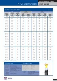
IN-POP & IN-POSP - Multi Cores 15<br />
IN-POP & IN-POSP - <strong>Sin</strong>gle & Multi Pairs 16<br />
IN-PIOP & IN-PIOSP - Multi Pairs 17<br />
IN-EOP & IN-EOSP - <strong>Sin</strong>gle & Multi Pairs 18<br />
IN-EIOP & IN-EIOSP - Multi Pairs 19<br />
XLPE / CT / AWA / PVC <strong>Cables</strong> - <strong>Sin</strong>gle Core 20<br />
XLPE / CT / SWA / PVC <strong>Cables</strong> - 4 Cores 21<br />
XLPE / CT / PVC <strong>Cables</strong> - 3 Cores + 3 Earth 22<br />
Schedule Of Installation Methods Of <strong>Cables</strong> 23<br />
Schedule Of Installation Methods Of <strong>Cables</strong> 24<br />
Current Rating and Voltage Drop (PVC Insulated <strong>Cables</strong>) 25<br />
Current Rating and Voltage Drop (XLPE Insulated <strong>Cables</strong>) 29<br />
Current Rating and Voltage Drop (Flexible <strong>Cables</strong>) 33<br />
Current Rating and Voltage Drop (<strong>Instrumentation</strong> <strong>Cables</strong>) 34<br />
Correction factors for Ambient Temperature & Group Installation 35<br />
Short Circuit Current for PVC Insulated & XLPE Insulated Installation 37<br />
Short Circuit Ratings 38<br />
Technical Information 39<br />
Conversion Tables of Conductor Size 40<br />
1
<strong>Power</strong> <strong>Cables</strong><br />
<strong>Sin</strong>gle Core<br />
Stranded Plain Annealed Copper Conductor<br />
Stranded Plain Annealed Copper Conductor BS 6360 & IEC 60228 Table 1<br />
Nominal<br />
No. and Nominal Maximum Weight<br />
Nominal Diameter Diameter Conductor per km<br />
Conductor of of Resistance of<br />
Area Wire Conductor at 20°C Conductor<br />
(mm 2 ) (no./mm) (mm) (Ω/km) (kg/km)<br />
1.0 7 / 0.43 1.29 18.1 9.2<br />
1.5 7 / 0.53 1.59 12.1 14.0<br />
2.5 7 / 0.67 2.01 7.41 22.4<br />
4 7 / 0.85 2.55 4.61 36.1<br />
6 7 / 1.04 3.12 3.08 54<br />
10 7 / 1.35 4.05 1.83 90.8<br />
16 7 / 1.70 5.10 1.15 145<br />
25 7 / 2.14 6.42 0.727 229<br />
35 7 / 2.52 7.56 0.524 317<br />
50 19 / 1.78 8.90 0.387 429<br />
70 19 / 2.14 10.70 0.268 620<br />
95 19 / 2.52 12.60 0.193 860<br />
120 37 / 2.03 14.21 0.153 1086<br />
150 37 / 2.25 15.75 0.124 1334<br />
185 37 / 2.52 17.64 0.0991 1673<br />
240 61 / 2.25 20.25 0.0754 2199<br />
300 61 / 2.52 22.68 0.0601 2759<br />
400 61 / 2.85 25.65 0.0470 3528<br />
500 61 / 3.20 28.80 0.0366 4448<br />
630 127 / 2.52 32.76 0.0283 5744<br />
800 127 / 2.85 37.05 0.0221 7346<br />
1000 127 / 3.20 41.60 0.0176 9260<br />
Construction<br />
1. Conductor : Plain Annealed Copper to BS 6360<br />
Technical Data<br />
Conductor Stranding : Class 1, 2 stranded circular or compacted conductors<br />
2
PVC <strong>Cables</strong> SS 358<br />
<strong>Power</strong> <strong>Cables</strong><br />
<strong>Sin</strong>gle Core<br />
PVC <strong>Cables</strong> SS 358 Table 2<br />
No. and Radial Mean Minimum<br />
Nominal Diameter Thickness Overall Insulation<br />
Conductor of of Diameter Approx. Resistance<br />
Area Wire Insulation (Upper Limit) Weight at 70°C<br />
(mm 2 ) (no./mm) (mm) (mm) (kg/km) (mΩ/km)<br />
1.5 7 / 0.53 0.7 3.4 22.7 0.010<br />
2.5 7 / 0.67 0.8 4.2 34.0 0.009<br />
4 7 / 0.85 0.8 4.8 50.0 0.0077<br />
6 7 / 1.04 0.8 5.4 70.9 0.0065<br />
10 7 / 1.35 1.0 6.8 117.5 0.0065<br />
16 7 / 1.70 1.0 8.0 177.4 0.0050<br />
25 7 / 2.14 1.2 9.8 279.5 0.0050<br />
35 7 / 2.52 1.2 11.0 372.0 0.0040<br />
50 19 / 1.78 1.4 13.0 504.5 0.0045<br />
70 19 / 2.14 1.4 15.0 710.6 0.0035<br />
95 19 / 2.52 1.6 17.0 980.8 0.0035<br />
120 37 / 2.03 1.6 19.0 1216.0 0.0032<br />
150 37 / 2.25 1.8 21.0 1498.0 0.0032<br />
185 37 / 2.52 2.0 23.5 1874.0 0.0032<br />
240 61 / 2.25 2.2 26.5 2444.4 0.0032<br />
300 61 / 2.52 2.4 29.5 3059.5 0.0030<br />
400 61 / 2.85 2.6 33.5 3897.0 0.0028<br />
500 61 / 3.20 2.8 37.0 4940.0 0.0028<br />
630 127 / 2.52 2.8 41.0 6295.0 0.0025<br />
Construction<br />
1. Conductor : Plain Annealed Copper to IEC 60228<br />
2. Insulation : PVC Compound Type C<br />
3. Colour : Red, Yellow, Blue, Black, Green, White,<br />
or Green/Yellow<br />
Technical Data<br />
Voltage Uo/U : 450 / 750 V<br />
Conductor Stranding : Class 1, 2 stranded circular<br />
or compacted conductors<br />
Operating Temperature : Maximum 70°C<br />
Minimum Bending Radius : 3D for D < 10 mm<br />
4D for 10 mm < D < 25 mm<br />
6D for D > 25 mm<br />
3
<strong>Power</strong> <strong>Cables</strong><br />
1 Core & 2 Cores<br />
PVC / PVC <strong>Cables</strong> IEC 60502<br />
PVC / PVC <strong>Cables</strong> IEC 60502 Table 3<br />
No. and<br />
Radial<br />
Nominal Diameter Thickness Approx.<br />
Conductor of of Overall Approx.<br />
Area Wire Insulation Diameter Weight<br />
(mm 2 ) (no./mm) (mm) (mm) (kg/km)<br />
1.5 7 / 0.53 0.8 6.3 55<br />
2.5 7 / 0.67 0.8 6.7 70<br />
4 7 / 0.85 1.0 7.6 100<br />
6 7 / 1.04 1.0 8.2 125<br />
10 7 / 1.35 1.0 9.2 175<br />
16 7 / 1.70 1.0 10.2 240<br />
25 7 / 2.14 1.2 11.9 350<br />
35 7 / 2.52 1.2 13.1 460<br />
50 19 / 1.78 1.4 14.8 595<br />
70 19 / 2.14 1.4 16.6 810<br />
95 19 / 2.52 1.6 19.2 1110<br />
120 37 / 2.03 1.6 20.8 1360<br />
150 37 / 2.25 1.8 23.0 1670<br />
185 37 / 2.52 2.0 25.4 2070<br />
240 61 / 2.25 2.2 28.7 2690<br />
300 61 / 2.52 2.4 31.7 3340<br />
400 61 / 2.85 2.6 35.3 4230<br />
500 61 / 3.20 2.8 39.5 5290<br />
630 127 / 2.52 2.8 43.2 6680<br />
800 127 / 2.85 2.8 47.7 8460<br />
1000 127 / 3.20 3.0 53.0 10545<br />
2 x 1.5 7 / 0.53 0.8 10.4 145<br />
2 x 2.5 7 / 0.67 0.8 11.2 180<br />
2 x 4 7 / 0.85 1.0 13.1 255<br />
2 x 6 7 / 1.04 1.0 14.2 285<br />
2 x 10 7 / 1.35 1.0 16.1 395<br />
2 x 16 7 / 1.70 1.0 18.2 590<br />
2 x 25 7 / 2.14 1.2 21.8 900<br />
2 x 35 7 / 2.52 1.2 24.0 1160<br />
2 x 50 (S) 19 / 1.78 1.4 23.0 1260<br />
2 x 70 (S) 19 / 2.14 1.4 26.0 1700<br />
2 x 95 (S) 19 / 2.52 1.6 30.0 2310<br />
2 x 120 (S) 37 / 2.03 1.6 32.0 2880<br />
2 x 150 (S) 37 / 2.25 1.8 36.0 3520<br />
2 x 185 (S) 37 / 2.52 2.0 40.0 4290<br />
2 x 240 (S) 61 / 2.25 2.2 44.0 5570<br />
2 x 300 (S) 61 / 2.52 2.4 49.0 6970<br />
Construction<br />
1. Conductor : Plain Annealed Copper to IEC 60228<br />
2. Insulation : PVC Compound Type A<br />
3. Sheath : PVC Compound Type ST1<br />
4. Colour : Insulation: 1 Core - Black<br />
2 Cores - Red & Black<br />
Sheath: 1 Core - Grey<br />
2 Cores - Black<br />
Technical Data<br />
Voltage Uo/U : 600 / 1000 V<br />
Conductor Stranding : Class 1, 2 stranded circular<br />
or compacted conductors<br />
Operating Temperature : Maximum 70°C<br />
Minimum Bending Radius : 1 Core –<br />
8D for 1.5mm 2 to 1000mm 2<br />
2 Cores –<br />
8D for 1.5mm 2 to 300mm 2<br />
4
PVC / PVC <strong>Cables</strong> IEC 60502<br />
<strong>Power</strong> <strong>Cables</strong><br />
3 Cores & 4 Cores<br />
PVC / PVC <strong>Cables</strong> IEC 60502 Table 4<br />
No. and<br />
Radial<br />
Nominal Diameter Thickness Approx.<br />
Conductor of of Overall Approx.<br />
Area Wire Insulation Diameter Weight<br />
(mm 2 ) (no./mm) (mm) (mm) (kg/km)<br />
3 x 1.5 7 / 0.53 0.8 10.9 165<br />
3 x 2.5 7 / 0.67 0.8 11.8 210<br />
3 x 4 7 / 0.85 1.0 13.8 305<br />
3 x 6 7 / 1.04 1.0 15.0 370<br />
3 x 10 7 / 1.35 1.0 17.1 515<br />
3 x 16 7 / 1.70 1.0 19.3 740<br />
3 x 25 7 / 2.14 1.2 23.2 1160<br />
3 x 35 7 / 2.52 1.2 25.7 1520<br />
3 x 50 (S) 19 / 1.78 1.4 26.0 1750<br />
3 x 70 (S) 19 / 2.14 1.4 29.0 2435<br />
3 x 95 (S) 19 / 2.52 1.6 34.0 3360<br />
3 x 120 (S) 37 / 2.03 1.6 37.0 4140<br />
3 x 150 (S) 37 / 2.25 1.8 40.0 5070<br />
3 x 185 (S) 37 / 2.52 2.0 45.0 6330<br />
3 x 240 (S) 61 / 2.25 2.2 51.2 8265<br />
3 x 300 (S) 61 / 2.52 2.4 56.0 10355<br />
4 x 1.5 7 / 0.53 0.8 11.7 200<br />
4 x 2.5 7 / 0.67 0.8 12.8 255<br />
4 x 4 7 / 0.85 1.0 15.0 375<br />
4 x 6 7 / 1.04 1.0 16.4 455<br />
4 x 10 7 / 1.35 1.0 18.6 665<br />
4 x 16 7 / 1.70 1.0 21.2 930<br />
4 x 25 7 / 2.14 1.2 25.6 1465<br />
4 x 35 7 / 2.52 1.2 28.4 1920<br />
4 x 35 (S) 7 / 2.52 1.2 26.0 1740<br />
4 x 50 (S) 19 / 1.78 1.4 29.0 2320<br />
4 x 70 (S) 19 / 2.14 1.4 33.0 3215<br />
4 x 95 (S) 19 / 2.52 1.6 39.0 4400<br />
4 x 120 (S) 37 / 2.03 1.6 42.5 5440<br />
4 x 150 (S) 37 / 2.25 1.8 47.0 6675<br />
4 x 185 (S) 37 / 2.52 2.0 52.0 8360<br />
4 x 240 (S) 61 / 2.25 2.2 58.2 10870<br />
4 x 300 (S) 61 / 2.52 2.4 65.0 13650<br />
Construction<br />
1. Conductor : Plain Annealed Copper to IEC 60228<br />
2. Insulation : PVC Compound Type A<br />
3. Sheath : PVC Compound Type ST1<br />
4. Colour : Insulation: 3 Cores - Red, Yellow, Blue<br />
4 Cores - Red, Yellow, Blue,<br />
Black<br />
Sheath: Black<br />
Technical Data<br />
Voltage Uo/U : 600 / 1000 V<br />
Conductor Stranding : Class 1, 2 stranded circular<br />
or compacted conductors<br />
Operating Temperature : Maximum 70°C<br />
Minimum Bending Radius : 8D for 1.5mm 2 to 300mm 2<br />
5
<strong>Power</strong> <strong>Cables</strong><br />
Multi Cores<br />
PVC / PVC <strong>Cables</strong><br />
PVC / PVC <strong>Cables</strong> Table 5<br />
No. and<br />
Radial<br />
No. Nominal Diameter Thickness Approx.<br />
of Conductor of of Overall Approx.<br />
Cores Area Wire Insulation Diameter Weight<br />
(mm 2 ) (no./mm) (mm) (mm) (kg/km)<br />
2 7 / 0.53 0.6 8.8 109<br />
3 7 / 0.53 0.6 9.2 129<br />
4 7 / 0.53 0.6 10.0 154<br />
5 7 / 0.53 0.6 10.8 190<br />
7 7 / 0.53 0.6 11.7 240<br />
10 1.5 7 / 0.53 0.6 14.8 330<br />
12 7 / 0.53 0.6 15.2 385<br />
19 7 / 0.53 0.6 17.9 560<br />
27 7 / 0.53 0.6 21.4 770<br />
37 7 / 0.53 0.6 24.0 1015<br />
48 7 / 0.53 0.6 27.6 1300<br />
2 7 / 0.67 0.7 10.0 148<br />
3 7 / 0.67 0.7 10.6 171<br />
4 7 / 0.67 0.7 11.5 218<br />
5 7 / 0.67 0.7 12.7 270<br />
7 7 / 0.67 0.7 13.7 340<br />
10 2.5 7 / 0.67 0.7 17.4 490<br />
12 7 / 0.67 0.7 18.0 560<br />
19 7 / 0.67 0.7 21.2 820<br />
27 7 / 0.67 0.7 25.4 1135<br />
37 7 / 0.67 0.7 28.6 1560<br />
48 7 / 0.67 0.7 33.0 1930<br />
2 7 / 0.85 0.8 11.5 205<br />
3 7 / 0.85 0.8 12.2 252<br />
4 7 / 0.85 0.8 13.3 315<br />
5 7 / 0.85 0.8 14.7 415<br />
7 7 / 0.85 0.8 16.2 535<br />
10 4 7 / 0.85 0.8 20.6 720<br />
12 7 / 0.85 0.8 21.3 850<br />
19 7 / 0.85 0.8 25.1 1260<br />
27 7 / 0.85 0.8 30.4 1740<br />
37 7 / 0.85 0.8 34.2 2300<br />
48 7 / 0.85 0.8 39.3 2900<br />
Construction<br />
1. Conductor : Plain Annealed Copper to BS 6360<br />
2. Insulation : PVC Compound Type TI1 to BS 6746<br />
3. Sheath : PVC Compound Type TM1 to BS 6746<br />
4. Colour : Insulation: White with Black numbers<br />
Sheath: Black<br />
Technical Data<br />
Voltage Uo/U : 600 / 1000 V<br />
Conductor Stranding : Class 2 stranded circular<br />
Operating Temperature : Maximum 70°C<br />
Minimum Bending Radius : 3D for D < 10 mm<br />
4D for 10 mm < D < 25 mm<br />
6D for D > 25 mm<br />
6
PVC / AWA / PVC <strong>Cables</strong> BS 6346<br />
<strong>Power</strong> <strong>Cables</strong><br />
<strong>Sin</strong>gle Core<br />
PVC / AWA / PVC <strong>Cables</strong> BS 6346 Table 6<br />
No. and<br />
Radial<br />
Nominal Diameter Thickness Approx.<br />
Conductor of of Overall Approx.<br />
Area Wire Insulation Diameter Weight<br />
(mm 2 ) (no./mm) (mm) (mm) (kg/km)<br />
50 19 / 1.78 1.4 19.1 760<br />
70 19 / 2.14 1.4 21.1 1010<br />
95 19 / 2.52 1.6 23.4 1330<br />
120 37 / 2.03 1.6 26.3 1690<br />
150 37 / 2.25 1.8 28.3 2010<br />
185 37 / 2.52 2.0 30.8 2450<br />
240 61 / 2.25 2.2 34.1 3120<br />
300 61 / 2.52 2.4 37.0 3810<br />
400 61 / 2.85 2.6 42.0 4890<br />
500 61 / 3.20 2.8 45.6 5990<br />
630 127 / 2.52 2.8 49.7 7510<br />
800 127 / 2.85 2.8 55.8 9590<br />
1000 127 / 3.20 3.0 61.0 11820<br />
Construction<br />
1. Conductor : Plain Annealed Copper to BS 6360<br />
2. Insulation : PVC Compound Type TI1 to BS 6746<br />
3. Bedding : PVC Compound Type TM1 to BS 6746<br />
4. Armour : Aluminium Wire<br />
5. Sheath : PVC Compound Type TM1 to BS 6746<br />
6. Colour : Insulation: Black<br />
Sheath: Black<br />
Technical Data<br />
Voltage Uo/U : 600 / 1000 V<br />
Conductor Stranding : Class 2 stranded circular<br />
or compacted conductors<br />
Operating Temperature : Maximum 70°C<br />
Minimum Bending Radius : 6D for 50mm 2 to 1000mm 2<br />
7
<strong>Power</strong> <strong>Cables</strong><br />
2 - 4 Cores<br />
PVC / SWA / PVC <strong>Cables</strong> BS 6346<br />
PVC / SWA / PVC <strong>Cables</strong> BS 6346 Table 7<br />
No. and<br />
Radial<br />
Nominal Diameter Thickness Approx.<br />
Conductor of of Overall Approx.<br />
Area Wire Insulation Diameter Weight<br />
(mm 2 ) (no./mm) (mm) (mm) (kg/km)<br />
2 x 1.5 7 / 0.53 0.6 12.3 270<br />
2 x 2.5 7 / 0.67 0.7 13.6 340<br />
2 x 4 7 / 0.85 0.8 15.1 450<br />
2 x 6 7 / 1.04 0.8 16.5 550<br />
2 x 10 7 / 1.35 1.0 20.1 750<br />
2 x 16 7 / 1.70 1.0 21.9 960<br />
2 x 25 7 / 2.14 1.2 26.7 1400<br />
2 x 35 7 / 2.52 1.2 29.4 1750<br />
2 x 50 (S) 19 / 1.78 1.4 27.4 1990<br />
2 x 70 (S) 19 / 2.14 1.4 30.0 2500<br />
2 x 95 (S) 19 / 2.52 1.6 34.7 2460<br />
2 x 120 (S) 37 / 2.03 1.6 37.2 4120<br />
2 x 150 (S) 37 / 2.25 1.8 40.5 4890<br />
2 x 185 (S) 37 / 2.52 2.0 45.2 6250<br />
2 x 240 (S) 61 / 2.25 2.2 50.0 7860<br />
2 x 300 (S) 61 / 2.52 2.4 54.8 9480<br />
3 x 1.5 7 / 0.53 0.6 12.8 350<br />
3 x 2.5 7 / 0.67 0.7 14.1 400<br />
3 x 4 7 / 0.85 0.8 15.8 520<br />
3 x 6 7 / 1.04 0.8 18.0 730<br />
3 x 10 7 / 1.35 1.0 21.2 1010<br />
3 x 16 7 / 1.70 1.0 23.1 1180<br />
3 x 25 7 / 2.14 1.2 28.2 1760<br />
3 x 35 7 / 2.52 1.2 30.8 2170<br />
3 x 50 (S) 19 / 1.78 1.4 30.1 2560<br />
3 x 70 (S) 19 / 2.14 1.4 34.2 3520<br />
3 x 95 (S) 19 / 2.52 1.6 38.5 4640<br />
3 x 120 (S) 37 / 2.03 1.6 41.4 5500<br />
3 x 150 (S) 37 / 2.25 1.8 46.3 6970<br />
3 x 185 (S) 37 / 2.52 2.0 50.7 8400<br />
3 x 240 (S) 61 / 2.25 2.2 56.2 10550<br />
3 x 300 (S) 61 / 2.52 2.4 61.6 12800<br />
4 x 1.5 7 / 0.53 0.6 13.5 345<br />
4 x 2.5 7 / 0.67 0.7 15.0 440<br />
4 x 4 7 / 0.85 0.8 17.8 710<br />
4 x 6 7 / 1.04 0.8 19.2 810<br />
4 x 10 7 / 1.35 1.0 22.8 1130<br />
4 x 16 7 / 1.70 1.0 26.3 1550<br />
4 x 25 7 / 2.14 1.2 30.7 2150<br />
4 x 35 7 / 2.52 1.2 33.7 2670<br />
4 x 35 (S) 7 / 2.52 1.2 29.9 2510<br />
4 x 50 (S) 19 / 1.78 1.4 34.6 3410<br />
4 x 70 (S) 19 / 2.14 1.4 38.4 4400<br />
4 x 95 (S) 19 / 2.52 1.6 43.5 5830<br />
4 x 120 (S) 37 / 2.03 1.6 48.1 7400<br />
4 x 150 (S) 37 / 2.25 1.8 52.4 8810<br />
4 x 185 (S) 37 / 2.52 2.0 57.4 10660<br />
4 x 240 (S) 61 / 2.25 2.2 64.1 13430<br />
4 x 300 (S) 61 / 2.52 2.4 70.4 16330<br />
Construction<br />
1. Conductor : Plain Annealed Copper to BS 6360<br />
2. Insulation : PVC Compound Type TI1 to BS 6746<br />
3. Bedding : PVC Compound Type TM1 to BS 6746<br />
or Lapped PVC Tape<br />
4. Armour : Galvanised Steel Wire<br />
5. Sheath : PVC Compound Type TM1 to BS 6746<br />
6. Colour : Insulation: 2 Cores - Red, Black<br />
3 Cores - Red, Yellow, Blue<br />
4 Cores - Red, Yellow, Blue,<br />
Black<br />
Sheath: Black<br />
Technical Data<br />
Voltage Uo/U : 600 / 1000 V<br />
Conductor Stranding : Class 1, 2 stranded circular<br />
or compacted conductors<br />
Operating Temperature : Maximum 70°C<br />
Minimum Bending Radius : 6D for 1.5mm 2 to 16mm 2<br />
8D for 25mm 2 and above<br />
8
PVC / SWA / PVC <strong>Cables</strong> BS 6346<br />
<strong>Power</strong> <strong>Cables</strong><br />
Multi Cores<br />
PVC / SWA / PVC <strong>Cables</strong> BS 6346 Table 8<br />
No. and<br />
Radial<br />
No. Nominal Diameter Thickness Approx.<br />
of Conductor of of Overall Approx.<br />
Cores Area Wire Insulation Diameter Weight<br />
(mm 2 ) (no./mm) (mm) (mm) (kg/km)<br />
5 7 / 0.53 0.6 14.3 357<br />
7 7 / 0.53 0.6 15.2 416<br />
10 7 / 0.53 0.6 19.0 446<br />
12 1.5 7 / 0.53 0.6 19.4 716<br />
19 7 / 0.53 0.6 22.2 938<br />
27 7 / 0.53 0.6 26.7 1380<br />
37 7 / 0.53 0.6 29.2 1689<br />
48 7 / 0.53 0.6 32.9 2048<br />
5 7 / 0.67 0.7 16.3 465<br />
7 7 / 0.67 0.7 18.0 557<br />
10 7 / 0.67 0.7 21.9 878<br />
12 2.5 7 / 0.67 0.7 22.4 955<br />
19 7 / 0.67 0.7 26.6 1455<br />
27 7 / 0.67 0.7 30.7 1885<br />
37 7 / 0.67 0.7 34.0 2340<br />
48 7 / 0.67 0.7 39.5 3190<br />
5 7 / 0.85 0.8 19.0 750<br />
7 7 / 0.85 0.8 20.5 905<br />
10 7 / 0.85 0.8 26.1 1405<br />
12 4 7 / 0.85 0.8 26.8 1530<br />
19 7 / 0.85 0.8 30.5 2060<br />
27 7 / 0.85 0.8 37.1 3025<br />
37 7 / 0.85 0.8 40.8 3900<br />
48 7 / 0.85 0.8 46.0 4800<br />
Construction<br />
1. Conductor : Plain Annealed Copper to BS 6360<br />
2. Insulation : PVC Compound Type TI1 to BS 6746<br />
3. Bedding : PVC Compound Type TM1 to BS 6746<br />
or Lapped PVC Tape<br />
4. Armour : Galvanised Steel Wire<br />
5. Sheath : PVC Compound Type TM1 to BS 6746<br />
6. Colour : Insulation: White with Black numberings<br />
Sheath: Black<br />
Technical Data<br />
Voltage Uo/U : 600 / 1000 V<br />
Conductor Stranding : Class 2 stranded circular<br />
conductors<br />
Operating Temperature : Maximum 70°C<br />
Minimum Bending Radius : 6D for 1.5mm 2 to 4mm 2<br />
9
<strong>Power</strong> <strong>Cables</strong><br />
2 - 4 Cores<br />
Flexible Cable, Circular Sheathed, Metric Unit<br />
Flexible Cable, Circular Sheathed, Metric Unit BS 6500 Table 9.1<br />
Conductor<br />
2 Cores<br />
Thickness Approx. Approx.<br />
Nominal of Overall Net<br />
Area Construction Insulation Diameter Weight<br />
(mm 2 ) (no./mm) (mm) (mm) (kg/km)<br />
0.5 16 / 0.20 0.6 6.1 55<br />
0.75 24 / 0.20 0.6 6.6 65<br />
1.0 32 / 0.20 0.6 6.9 75<br />
1.25 40 / 0.20 0.7 7.6 80<br />
1.5 30 / 0.25 0.7 7.8 90<br />
2.5 50 / 0.25 0.8 9.6 135<br />
4.0 56 / 0.30 0.8 11.0 135<br />
Flexible Cable, Circular Sheathed, Metric Unit BS 6500 Table 9.2<br />
Conductor<br />
3 Cores<br />
Thickness Approx. Approx.<br />
Nominal of Overall Net<br />
Area Construction Insulation Diameter Weight<br />
(mm 2 ) (no./mm) (mm) (mm) (kg/km)<br />
0.5 16 / 0.20 0.6 6.5 60<br />
0.75 24 / 0.20 0.6 6.9 75<br />
1.0 32 / 0.20 0.6 7.3 85<br />
1.25 40 / 0.20 0.7 8.3 100<br />
1.5 30 / 0.25 0.7 8.5 110<br />
2.5 50 / 0.25 0.8 10.4 170<br />
4.0 56 / 0.30 0.8 11.8 215<br />
Flexible Cable, Circular Sheathed, Metric Unit BS 6500 Table 9.3<br />
Conductor<br />
4 Cores<br />
Thickness Approx. Approx.<br />
Nominal of Overall Net<br />
Area Construction Insulation Diameter Weight<br />
(mm 2 ) (no./mm) (mm) (mm) (kg/km)<br />
0.5 16 / 0.20 0.6 7.1 75<br />
0.75 24 / 0.20 0.6 7.6 90<br />
1.0 32 / 0.20 0.6 8.2 110<br />
1.25 40 / 0.20 0.6 - -<br />
1.5 30 / 0.25 0.7 9.5 140<br />
2.5 50 / 0.25 0.8 11.4 205<br />
4.0 56 / 0.30 0.8 12.9 275<br />
Construction<br />
1. Conductor : Plain Annealed Copper to BS 6360<br />
2. Insulation : PVC Compound Type TI2 to BS 7655<br />
3. Assembly : 2, 3 or 4 Cores are Twisted Together<br />
4. Sheath : PVC Compound Type TM2 to BS 7655<br />
Technical Data<br />
Voltage Uo/U : 300 / 500 V<br />
Conductor Stranding : Class 2<br />
Operating Temperature : 70°<br />
10
Flexible Cord, Twin Twisted Non-Sheathed, Imperial Unit<br />
<strong>Power</strong> <strong>Cables</strong><br />
<strong>Sin</strong>gle Core<br />
Flexible Cord, Twin Twisted Non-Sheathed, Imperial Unit BS 2004 Table 10.1<br />
Conductor<br />
Twin Twisted<br />
Thickness Approx. Approx.<br />
Nominal of Overall Net<br />
Area Construction Insulation Diameter Weight<br />
(mm 2 ) (no./in) (mm) (mm) (kg/100y)<br />
0.41 14 / 0.0076 0.64 2.1 1.7<br />
0.67 23 / 0.0076 0.64 2.4 2.3<br />
1.17 40 / 0.0076 0.64 2.7 3.1<br />
Construction<br />
1. Conductor : Plain Annealed Copper to BS 6360<br />
2. Insulation : PVC Compound Type TI1 to BS 6746<br />
3. Assembly : Two Cores Twisted<br />
Technical Data<br />
Voltage Uo/U : 250 / 440 V<br />
Conductor Stranding : Class 2<br />
Operating Temperature : 70°<br />
Flexible Cable, Circular Sheathed, Imperial Unit<br />
<strong>Power</strong> <strong>Cables</strong><br />
1 - 4 Cores<br />
Flexible Cable, Circular Sheathed, Imperial Unit BS 2004 Table 10.2<br />
Conductor 1 Core 2 Cores<br />
Thickness Approx. Approx. Approx. Approx.<br />
Nominal of Overall Net Overall Net<br />
Area Construction Insulation Diameter Weight Diameter Weight<br />
(mm 2 ) (no./in) (mm) (mm) (kg/100y) (mm) (kg/100y)<br />
0.41 14 / 0.0076 0.64 4.2 2.1 6.3 4.8<br />
0.67 23 / 0.0076 0.64 4.4 2.5 6.8 6.0<br />
1.17 40 / 0.0076 0.64 4.8 3.2 7.5 7.5<br />
2.05 70 / 0.0076 0.64 5.2 4.2 9.0 10.0<br />
3.22 110 / 0.0076 0.64 5.7 5.4 10.0 12.9<br />
4.74 162 / 0.0076 0.76 6.4 7.3 11.3 17.4<br />
Flexible Cable, Circular Sheathed, Imperial Unit BS 2004 Table 10.3<br />
Conductor 3 Cores 4 Cores<br />
Thickness Approx. Approx. Approx. Approx.<br />
Nominal of Overall Net Overall Net<br />
Area Construction Insulation Diameter Weight Diameter Weight<br />
(mm 2 ) (no./in) (mm) (mm) (kg/100y) (mm) (kg/100y)<br />
0.41 14 / 0.0076 0.64 6.6 5.6 7.2 6.2<br />
0.67 23 / 0.0076 0.64 7.1 6.2 7.7 7.9<br />
1.17 40 / 0.0076 0.64 7.9 8.9 9.2 10.0<br />
2.05 70 / 0.0076 0.64 9.5 12.7 10.3 15.4<br />
3.22 110 / 0.0076 0.64 10.5 16.6 11.4 20.4<br />
4.74 162 / 0.0076 0.76 12.2 22.9 13.2 28.3<br />
Construction<br />
1. Conductor : Plain Annealed Copper to BS 6360<br />
2. Insulation : PVC Compound Type TI1 to BS 6746<br />
3. Assembly : 1, 2, 3 or 4 Cores Twisted Together<br />
4. Sheath : PVC Compound Type T6 to BS 6746<br />
Technical Data<br />
Voltage Uo/U : 250 / 440 V<br />
Conductor Stranding : Class 2<br />
Operating Temperature : 70°<br />
11
<strong>Power</strong> <strong>Cables</strong><br />
<strong>Sin</strong>gle Core<br />
XLPE / PVC & XLPE / AWA / PVC <strong>Cables</strong> IEC 60502<br />
XLPE / PVC & XLPE / AWA / PVC <strong>Cables</strong> IEC 60502 Table 11<br />
XP<br />
XAP<br />
No. and Radial<br />
Nominal Diameter Thickness Cable Diameter Armour Cable<br />
Conductor of of Overall Approx. Under Wire Overall Approx.<br />
Area Wire Insulation Diameter Weight Armour Diameter Diameter Weight<br />
(mm 2 ) (no./mm) (mm) (mm) (kg/km) (mm) (mm) (mm) (kg/km)<br />
16 7 / 1.70 0.7 9.6 205 — — — —<br />
25 7 / 2.14 0.9 11.3 309 10.6 0.9 16.0 470<br />
35 7 / 2.52 0.9 12.5 412 11.8 0.9 17.2 581<br />
50 19 / 1.78 1.0 14.0 540 13.3 1.25 19.4 800<br />
70 19 / 2.14 1.1 16.1 760 15.4 1.25 21.5 960<br />
95 19 / 2.52 1.1 18.2 1020 17.3 1.25 23.4 1240<br />
120 37 / 2.03 1.2 20.0 1270 19.1 1.6 25.9 1650<br />
150 37 / 2.25 1.4 22.2 1560 21.0 1.60 27.9 1970<br />
185 37 / 2.52 1.6 24.4 1930 23.3 1.60 30.1 2390<br />
240 61 / 2.25 1.7 27.5 2510 26.1 1.6 33.2 3040<br />
300 61 / 2.52 1.8 30.3 3120 28.7 1.6 35.8 3790<br />
400 61 / 2.85 2.0 33.9 3970 32.1 2.0 40.9 4790<br />
500 61 / 3.20 2.2 37.6 4980 35.7 2.0 44.6 5880<br />
630 127 / 2.52 2.4 42.4 6400 40.4 2.0 49.2 7400<br />
800 127 / 2.85 2.6 47.3 8190 45.1 2.5 55.7 9500<br />
1000 127 / 3.20 2.8 52.4 10265 50.1 2.5 61.0 11750<br />
Construction<br />
1. Conductor : Plain Annealed Copper to IEC 60228<br />
2. Insulation : XLPE Compound<br />
3. Bedding : PVC Compound Type ST2<br />
4. Armour : Aluminium Wire<br />
5. Sheath : PVC Compound Type ST2<br />
6. Colour : Insulation: Natural<br />
Sheath: Black<br />
Technical Data<br />
Voltage Uo/U : 600 / 1000 V<br />
Conductor Stranding : Class 2 stranded circular<br />
or compacted conductors<br />
Operating Temperature : Maximum 90°C<br />
Minimum Bending Radius : Unarmoured:<br />
8D for 16mm 2 to 1000mm 2<br />
Armoured:<br />
10D for 25mm 2 to 1000mm 2<br />
12
XLPE / PVC & XLPE / SWA / PVC <strong>Cables</strong> IEC 60502<br />
<strong>Power</strong> <strong>Cables</strong><br />
2 - 4 Cores<br />
XLPE / PVC & XLPE / SWA / PVC <strong>Cables</strong> IEC 60502 Table 12<br />
XP<br />
XSP<br />
No. and Radial<br />
Nominal Diameter Thickness Cable Diameter Armour Cable<br />
Conductor of of Overall Approx. Under Wire Overall Approx.<br />
Area Wire Insulation Diameter Weight Armour Diameter Diameter Weight<br />
(mm 2 ) (no./mm) (mm) (mm) (kg/km) (mm) (mm) (mm) (kg/km)<br />
2 x 1.5 7 / 0.53 0.7 10.0 130 8.5 0.9 13.9 350<br />
2 x 2.5 7 / 0.67 0.7 10.8 165 9.3 0.9 14.7 400<br />
2 x 4 7 / 0.85 0.7 11.9 210 10.4 0.9 15.8 475<br />
2 x 6 7 / 1.04 0.7 13.0 270 11.5 0.9 16.9 560<br />
2 x 10 7 / 1.35 0.7 14.9 390 13.4 1.25 19.5 810<br />
2 x 16 7 / 1.70 0.7 17.0 450 15.5 1.25 21.6 980<br />
2 x 25 7 / 2.14 0.9 20.4 820 18.9 1.6 25.7 1410<br />
2 x 35 7 / 2.52 0.9 22.7 1065 21.2 1.6 28.0 1930<br />
2 x 50 (S) 19 / 1.78 1.0 21.0 1140 19.2 1.6 26.0 1880<br />
2 x 70 (S) 19 / 2.14 1.1 24.0 1560 22.3 1.6 29.5 2420<br />
2 x 95 (S) 19 / 2.52 1.1 26.9 2130 25.3 2.0 33.5 3360<br />
2 x 120 (S) 37 / 2.03 1.2 29.9 2640 28.1 2.0 36.5 3980<br />
2 x 150 (S) 37 / 2.25 1.4 33.4 3270 30.9 2.0 39.5 4730<br />
2 x 185 (S) 37 / 2.52 1.6 37.1 4040 36.0 2.0 45.0 6245<br />
2 x 240 (S) 61 / 2.25 1.7 45.0 5150 41.6 2.5 52.0 7820<br />
2 x 300 (S) 61 / 2.52 1.8 50.0 6560 47.4 2.5 58.0 9390<br />
3 x 1.5 7 / 0.53 0.7 10.5 150 9.0 0.9 14.4 390<br />
3 x 2.5 7 / 0.67 0.7 11.4 195 9.9 0.9 15.3 450<br />
3 x 4 7 / 0.85 0.7 12.5 255 11.0 0.9 16.4 540<br />
3 x 6 7 / 1.04 0.7 13.8 330 12.3 0.9 17.7 745<br />
3 x 10 7 / 1.35 0.7 15.8 490 14.3 1.25 20.4 950<br />
3 x 16 7 / 1.70 0.7 18.0 700 16.5 1.25 22.6 1250<br />
3 x 25 7 / 2.14 0.9 21.7 1000 20.2 1.6 27.0 1840<br />
3 x 35 7 / 2.52 0.9 24.2 1300 23.0 1.6 29.8 2280<br />
3 x 50 (S) 19 / 1.78 1.0 25.0 1600 23.0 1.6 30.0 2550<br />
3 x 70 (S) 19 / 2.14 1.1 29.0 2240 27.0 2.0 35.0 3500<br />
3 x 95 (S) 19 / 2.52 1.1 32.0 3050 30.1 2.0 38.5 4500<br />
3 x 120 (S) 37 / 2.03 1.2 36.5 3800 34.4 2.0 43.0 5700<br />
3 x 150 (S) 37 / 2.25 1.4 39.0 4640 37.5 2.5 47.5 6800<br />
3 x 185 (S) 37 / 2.52 1.6 44.0 5870 41.3 2.5 51.5 8200<br />
3 x 240 (S) 61 / 2.25 1.7 49.0 7670 46.4 2.5 57.0 10300<br />
3 x 300 (S) 61 / 2.52 1.8 55.0 9460 52.0 2.5 63.0 12500<br />
4 x 1.5 7 / 0.53 0.7 11.3 175 10.0 0.9 15.4 430<br />
4 x 2.5 7 / 0.67 0.7 12.3 225 10.8 0.9 16.2 505<br />
4 x 4 7 / 0.85 0.7 13.6 305 12.1 0.9 17.5 710<br />
4 x 6 7 / 1.04 0.7 15.0 405 13.5 1.25 19.6 855<br />
4 x 10 7 / 1.35 0.7 17.2 600 15.7 1.25 21.8 1120<br />
4 x 16 7 / 1.70 0.7 19.7 870 18.2 1.6 25.0 1600<br />
4 x 25 7 / 2.14 0.9 23.9 1325 22.4 1.6 29.2 2160<br />
4 x 35 7 / 2.52 0.9 26.6 1760 25.1 1.6 32.1 2750<br />
4 x 35 (S) 7 / 2.52 0.9 25.0 1600 24.0 1.6 31.0 2500<br />
4 x 50 (S) 19 / 1.78 1.0 28.5 2200 26.8 1.6 34.0 3100<br />
4 x 70 (S) 19 / 2.14 1.1 32.0 3050 30.6 2.0 39.0 4400<br />
4 x 95 (S) 19 / 2.52 1.1 37.0 4070 34.4 2.0 43.0 5610<br />
4 x 120 (S) 37 / 2.03 1.2 42.0 5195 36.0 2.5 46.0 7400<br />
4 x 150 (S) 37 / 2.25 1.4 46.0 6350 38.3 2.5 48.5 8300<br />
4 x 185 (S) 37 / 2.52 1.6 50.0 7890 46.4 2.5 57.0 10400<br />
4 x 240 (S) 61 / 2.25 1.7 55.0 10400 51.0 2.5 62.0 13000<br />
4 x 300 (S) 61 / 2.52 1.8 63.0 12810 56.6 2.5 68.0 15900<br />
Construction<br />
1. Conductor : Plain Annealed Copper to IEC 60228<br />
2. Insulation : XLPE Compound<br />
3. Bedding : PVC Compound Type ST2 or<br />
Lapped PVC Tape<br />
4. Armour : Galvanised Steel Wire<br />
5. Sheath : PVC Compound Type ST2<br />
6. Colour : Insulation: 2 Cores - Red, Black<br />
3 Cores - Red, Yellow, Blue<br />
4 Cores - Red, Yellow, Blue,<br />
Black<br />
Sheath: Black<br />
Technical Data<br />
Voltage Uo/U : 600 / 1000 V<br />
Conductor Stranding : Class 2 stranded circular<br />
or compacted conductors<br />
Operating Temperature : Maximum 90°C<br />
Minimum Bending Radius : Unarmoured:<br />
6D for 1.5mm 2 to 300mm 2<br />
Armoured:<br />
8D for 25mm 2 to 1000mm 2<br />
13
<strong>Power</strong> <strong>Cables</strong><br />
Multi Cores<br />
XLPE / PVC & XLPE / SWA / PVC <strong>Cables</strong> IEC 60502<br />
XLPE / PVC & XLPE / SWA / PVC <strong>Cables</strong> IEC 60502 Table 13<br />
XP<br />
XSP<br />
No. and Radial<br />
No. Nominal Diameter Thickness Cable Diameter Armour Cable<br />
of Conductor of of Overall Approx. Under Wire Overall Approx.<br />
Cores Area Wire Insulation Diameter Weight Armour Diameter Diameter Weight<br />
(mm 2 ) (no./mm) (mm) (mm) (kg/km) (mm) (mm) (mm) (kg/km)<br />
5 7/0.53 0.7 11.9 214.5 10.5 0.9 15.9 493.9<br />
7 7/0.53 0.7 12.9 235.5 11.5 0.9 16.9 560.7<br />
12 1.5 7/0.53 0.7 16.5 391.1 15.1 1.25 21.2 903.9<br />
19 7/0.53 0.7 19.4 522.0 17.7 1.25 23.8 1167.8<br />
37 7/0.53 0.7 25.4 981.0 23.3 1.6 30.1 1872.0<br />
5 7/0.67 0.7 13.1 280.4 11.7 0.9 17.1 586.8<br />
7 7/0.67 0.7 14.1 317.5 12.7 0.9 18.1 676.1<br />
12 2.5 7/0.67 0.7 18.4 500.0 16.8 1.25 22.9 1095.8<br />
19 7/0.67 0.7 21.4 737.0 19.8 1.6 26.6 1593.2<br />
37 7/0.67 0.7 28.4 1327.0 27.0 1.6 33.8 2361.0<br />
5 7/0.85 0.7 14.5 381.6 13.1 1.25 19.2 823.0<br />
7 7/0.85 0.7 16.0 470.0 14.3 1.25 20.4 906.0<br />
12 4 7/0.85 0.7 20.6 709.0 18.6 1.25 24.7 1293.0<br />
19 7/0.85 0.7 24.1 1051.0 22.0 1.6 28.8 1904.0<br />
37 7/0.85 0.7 32.2 1989.0 30.1 1.6 36.9 2919.0<br />
Construction<br />
1. Conductor : Plain Annealed Copper to IEC 60228<br />
2. Insulation : XLPE Compound<br />
3. Bedding : PVC Compound Type ST2 or<br />
Lapped PVC Tape<br />
4. Armour : Galvanised Steel Wire<br />
5. Sheath : PVC Compound Type ST2<br />
6. Colour : Insulation: White with Black numberings<br />
Sheath: Black<br />
Technical Data<br />
Voltage Uo/U : 600 / 1000 V<br />
Conductor Stranding : Class 2 stranded circular<br />
Operating Temperature : Maximum 90°C<br />
Minimum Bending Radius : Unarmoured:<br />
6D for 1.5mm 2 to 4mm 2<br />
Armoured:<br />
8D for 1.5mm 2 to 4mm 2<br />
14
IN-POP & IN-POSP <strong>Cables</strong><br />
<strong>Instrumentation</strong> <strong>Cables</strong><br />
Multi Cores<br />
IN-POP & IN-POSP <strong>Cables</strong> Table 14<br />
SIZE IN-POP IN-POSP<br />
No. and Radial Unarmoured Armoured<br />
Nominal Diameter Thickness Cable Diameter Armour Cable<br />
Conductor of of Overall Approx. Under Wire Overall Approx.<br />
Area Wire Insulation Diameter Weight Armour Diameter Diameter Weight<br />
(mm 2 ) (no./mm) (mm) (mm) (kg/km) (mm) (mm) (mm) (kg/km)<br />
2C x 0.5 16/0.2 0.6 7.0 60 7.0 0.90 11.4 250<br />
3C x 0.5 16/0.2 0.6 7.3 68 7.3 0.90 11.7 265<br />
4C x 0.5 16/0.2 0.6 7.9 78 7.9 0.90 12.3 290<br />
6C x 0.5 16/0.2 0.6 9.3 110 9.3 0.90 13.9 360<br />
10C x 0.5 16/0.2 0.6 11.9 170 11.9 0.90 16.7 490<br />
20C x 0.5 16/0.2 0.6 14.9 295 14.9 1.25 20.6 800<br />
40C x 0.5 16/0.2 0.6 20.1 510 20.1 1.60 26.7 1300<br />
80C x 0.5 16/0.2 0.6 26.3 950 26.3 1.60 33.3 2050<br />
2C x 0.75 24/0.2 0.6 7.3 65 7.3 0.90 11.7 260<br />
3C x 0.75 24/0.2 0.6 7.7 78 7.7 0.90 12.1 280<br />
4C x 0.75 24/0.2 0.6 8.3 92 8.3 0.90 12.9 320<br />
6C x 0.75 24/0.2 0.6 9.9 128 9.9 0.90 14.5 400<br />
10C x 0.75 24/0.2 0.6 12.7 200 12.7 0.90 17.5 550<br />
20C x 0.75 24/0.2 0.6 16.0 355 16.0 1.25 21.7 905<br />
40C x 0.75 24/0.2 0.6 21.7 640 21.7 1.60 28.5 1500<br />
80C x 0.75 24/0.2 0.6 28.5 1185 28.5 1.60 35.7 2420<br />
2C x 1.5 7/0.53 0.6 8.3 90 8.3 0.90 12.9 310<br />
3C x 1.5 7/0.53 0.6 8.9 115 8.9 0.90 13.5 360<br />
4C x 1.5 7/0.53 0.6 9.7 140 9.7 0.90 14.3 400<br />
6C x 1.5 7/0.53 0.6 11.7 200 11.7 0.90 16.3 515<br />
10C x 1.5 7/0.53 0.6 14.7 315 14.7 1.25 20.4 820<br />
20C x 1.5 7/0.53 0.6 18.7 560 18.7 1.60 25.3 1340<br />
40C x 1.5 7/0.53 0.6 24.6 1040 24.6 1.60 31.6 2090<br />
80C x 1.5 7/0.53 0.6 33.6 1970 33.6 2.00 41.8 3690<br />
pair configurations are available upon request.<br />
Construction<br />
1. Conductor : Plain Annealed Copper to BS 6360<br />
2. Insulation : PVC Compound Type TI1 to BS 6746<br />
3. Lay Up : Cores are stranded in Reverse Layer<br />
Technique forming a Concentric Cable<br />
4. Wrap Film : Polyester Binder Tape<br />
5. Collective : Aluminium/Polyester Tape, with a Tinned<br />
Screen Copper Drain Wire 0.5mm 2 (7/0.3mm)<br />
6. Bedding<br />
(Optional)<br />
: PVC Compound Type ST2 to BS 6746<br />
7. Armouring<br />
(Optional)<br />
: Galvanized Steel Wires to BS 1442<br />
Technical Data<br />
Reference Standards : BS 5308 Part 2<br />
Voltage Uo/U : 300 / 500 V<br />
Conductor Stranding : Class 1 and 2<br />
Operating Temperature : 70°C<br />
Testing Voltage : 1 KV / 1 Minute<br />
8. Sheath : PVC Compound Type ST2 to BS 6746<br />
9. Colour : Insulation: White with Black numberings<br />
or refer to colour code<br />
Sheath: Black<br />
15
<strong>Instrumentation</strong> <strong>Cables</strong><br />
<strong>Sin</strong>gle & Multi Pairs<br />
IN-POP & IN-POSP <strong>Cables</strong><br />
IN-POP & IN-POSP <strong>Cables</strong> Table 15<br />
SIZE IN-POP IN-POSP<br />
No. and Radial Unarmoured Armoured<br />
Nominal Diameter Thickness Cable Diameter Armour Cable<br />
Conductor of of Overall Approx. Under Wire Overall Approx.<br />
Area Wire Insulation Diameter Weight Armour Diameter Diameter Weight<br />
(mm 2 ) (no./mm) (mm) (mm) (kg/km) (mm) (mm) (mm) (kg/km)<br />
1P x 0.5 16/0.2 0.6 7.0 60 7.0 0.90 11.4 250<br />
2P(Quad) x 0.5 16/0.2 0.6 7.9 78 7.9 0.90 12.3 290<br />
5P x 0.5 16/0.2 0.6 13.1 185 13.1 0.90 17.9 540<br />
10P x 0.5 16/0.2 0.6 17.2 310 17.2 1.25 22.9 905<br />
15P x 0.5 16/0.2 0.6 19.8 430 19.8 1.60 26.4 1270<br />
20P x 0.5 16/0.2 0.6 22.3 540 22.3 1.60 29.1 1490<br />
30P x 0.5 16/0.2 0.6 26.9 780 26.9 1.60 33.9 1960<br />
50P x 0.5 16/0.2 0.6 33.9 1240 33.9 2.00 42.1 3000<br />
1P x 0.75 24/0.2 0.6 7.3 68 7.3 0.90 11.7 260<br />
2P(Quad) x 0.75 24/0.2 0.6 8.3 92 8.3 0.90 12.9 325<br />
5P x 0.75 24/0.2 0.6 14.3 230 14.3 1.25 19.8 710<br />
10P x 0.75 24/0.2 0.6 18.7 390 18.7 1.60 25.3 1170<br />
15P x 0.75 24/0.2 0.6 21.4 530 21.4 1.60 28.2 1460<br />
20P x 0.75 24/0.2 0.6 24.5 690 24.5 1.60 31.3 1750<br />
30P x 0.75 24/0.2 0.6 29.5 1010 29.5 2.00 37.5 2560<br />
50P x 0.75 24/0.2 0.6 37.4 1610 37.4 2.00 45.8 3550<br />
1P x 1.5 7/0.53 0.6 8.3 90 8.3 0.90 12.9 310<br />
2P(Quad) x 1.5 7/0.53 0.6 9.7 142 9.7 0.90 14.3 410<br />
5P x 1.5 7/0.53 0.6 16.4 330 16.4 1.25 22.1 900<br />
10P x 1.5 7/0.53 0.6 21.6 580 21.6 1.60 28.4 1510<br />
15P x 1.5 7/0.53 0.6 25.2 860 25.2 1.60 32.2 1950<br />
20P x 1.5 7/0.53 0.6 28.5 1090 28.5 1.60 35.7 2330<br />
30P x 1.5 7/0.53 0.6 34.3 1600 34.3 2.00 42.5 3400<br />
50P x 1.5 7/0.53 0.6 43.6 2570 43.6 2.50 53.4 5320<br />
pair configurations are available upon request.<br />
Construction<br />
1. Conductor : Plain Annealed Copper to BS 6360<br />
2. Insulation : PVC Compound Type TI1 to BS 6746<br />
3. Lay Up : Cores are paired, pairs are twisted in<br />
Reverse Layer Technique forming a<br />
Concentric Cable<br />
4. Wrap Film : Polyester Binder Tape<br />
5. Collective : Aluminium/Polyester Tape, with a Tinned<br />
Screen Copper Drain Wire 0.5mm 2 (7/0.3mm)<br />
6. Bedding : PVC Compound Type ST2 to BS 6746<br />
(Optional)<br />
Technical Data<br />
Reference Standards : BS 5308 Part 2<br />
Voltage Uo/U : 300 / 500 V<br />
Conductor Stranding : Class 1 and 2<br />
Operating Temperature : 70°C<br />
Testing Voltage : 1 KV / 1 Minute<br />
7. Armouring<br />
(Optional)<br />
: Galvanized Steel Wires to BS 1442<br />
8. Sheath : PVC Compound Type ST2 to BS 6746<br />
9. Colour : Insulation: White with Black numberings<br />
or refer to colour code<br />
Sheath: Black<br />
16
IN-PIOP & IN-PIOSP <strong>Cables</strong><br />
<strong>Instrumentation</strong> <strong>Cables</strong><br />
Multi Pairs<br />
IN-PIOP & IN-PIOSP <strong>Cables</strong> Table 16<br />
SIZE IN-PIOP IN-PIOSP<br />
No. and Radial Unarmoured Armoured<br />
Nominal Diameter Thickness Cable Diameter Armour Cable<br />
Conductor of of Overall Approx. Under Wire Overall Approx.<br />
Area Wire Insulation Diameter Weight Armour Diameter Diameter Weight<br />
(mm 2 ) (no./mm) (mm) (mm) (kg/km) (mm) (mm) (mm) (kg/km)<br />
2P x 0.5 16/0.2 0.6 12.0 135 12.0 0.90 16.8 470<br />
5P x 0.5 16/0.2 0.6 15.2 240 15.2 1.25 20.9 770<br />
10P x 0.5 16/0.2 0.6 21.1 410 21.1 1.60 27.9 1320<br />
15P x 0.5 16/0.2 0.6 24.5 590 24.5 1.60 31.3 1640<br />
20P x 0.5 16/0.2 0.6 27.3 750 27.3 1.60 34.3 1910<br />
30P x 0.5 16/0.2 0.6 32.3 1090 32.3 2.00 40.5 2740<br />
50P x 0.5 16/0.2 0.6 41.7 1780 41.7 2.50 51.5 4400<br />
2P x 0.75 24/0.2 0.6 12.8 155 12.8 0.90 17.6 505<br />
5P x 0.75 24/0.2 0.6 16.3 275 16.3 1.25 22.0 850<br />
10P x 0.75 24/0.2 0.6 22.7 480 22.7 1.60 29.5 1450<br />
15P x 0.75 24/0.2 0.6 26.4 700 26.4 1.60 33.4 1830<br />
20P x 0.75 24/0.2 0.6 29.8 900 29.8 2.00 37.8 2430<br />
30P x 0.75 24/0.2 0.6 35.5 1310 35.5 2.00 43.9 3190<br />
50P x 0.75 24/0.2 0.6 45.0 2060 45.0 2.50 55.0 4970<br />
2P x 1.5 7/0.53 0.6 14.7 215 14.7 1.25 20.4 730<br />
5P x 1.5 7/0.53 0.6 18.8 400 18.8 1.60 25.4 1200<br />
10P x 1.5 7/0.53 0.6 26.5 740 26.5 1.60 33.5 1860<br />
15P x 1.5 7/0.53 0.6 30.8 1060 30.8 2.00 38.8 2660<br />
20P x 1.5 7/0.53 0.6 34.4 1340 34.4 2.00 42.6 3100<br />
30P x 1.5 7/0.53 0.6 41.0 1970 41.0 2.50 50.8 4550<br />
50P x 1.5 7/0.53 0.6 52.2 3130 52.2 2.50 62.6 6420<br />
pair configurations are available upon request.<br />
Construction<br />
1. Conductor : Plain Annealed Copper to BS 6360<br />
2. Insulation : PVC Compound Type TI1 to BS 6746<br />
3. Lay Up : Cores are paired, pairs are twisted in<br />
Reverse Layer Technique forming a<br />
Concentric Cable<br />
4. Individual : Aluminium/Polyester Tape, with a Tinned<br />
Screen Copper Drain Wire 0.5mm 2 (7/0.3mm)<br />
5. Wrap Film : Polyester Binder Tape<br />
6. Collective : Aluminium/Polyester Tape, with a Tinned<br />
Screen Copper Drain Wire 0.5mm 2 (7/0.3mm)<br />
7. Bedding : PVC Compound Type ST2 to BS 6746<br />
(Optional)<br />
Technical Data<br />
Reference Standards : BS 5308 Part 2<br />
Voltage Uo/U : 300 / 500 V<br />
Conductor Stranding : Class 1 and 2<br />
Operating Temperature : 70°C<br />
Testing Voltage : 1 KV / 1 Minute<br />
8. Armouring : Galvanized Steel Wires to BS 1442<br />
(Optional)<br />
9. Sheath : PVC Compound Type ST2 to BS 6746<br />
10. Colour : Insulation: White with Black numberings<br />
or refer to colour code<br />
Sheath: Black<br />
17
<strong>Instrumentation</strong> <strong>Cables</strong><br />
<strong>Sin</strong>gle & Multi Pairs<br />
IN-EOP & IN-EOSP <strong>Cables</strong><br />
IN-EOP & IN-EOSP <strong>Cables</strong> Table 17<br />
SIZE IN-EOP IN-EOSP<br />
No. and Radial Unarmoured Armoured<br />
Nominal Diameter Thickness Cable Diameter Armour Cable<br />
Conductor of of Overall Approx. Under Wire Overall Approx.<br />
Area Wire Insulation Diameter Weight Armour Diameter Diameter Weight<br />
(mm 2 ) (no./mm) (mm) (mm) (kg/km) (mm) (mm) (mm) (kg/km)<br />
1P x 0.5 16/0.2 0.6 7.0 56 7.0 0.90 11.4 230<br />
2P(Quad) x 0.5 16/0.2 0.6 7.9 70 7.9 0.90 12.3 270<br />
5P x 0.5 16/0.2 0.6 13.1 170 13.1 0.90 17.9 500<br />
10P x 0.5 16/0.2 0.6 17.2 280 17.2 1.25 22.9 830<br />
15P x 0.5 16/0.2 0.6 19.8 385 19.8 1.60 26.4 1150<br />
20P x 0.5 16/0.2 0.6 22.3 480 22.3 1.60 29.1 1360<br />
30P x 0.5 16/0.2 0.6 26.9 690 26.9 1.60 33.9 1750<br />
50P x 0.5 16/0.2 0.6 33.9 1080 33.9 2.00 42.1 2730<br />
1P x 1.0 7/0.43 0.6 7.4 68 7.4 0.90 11.8 250<br />
2P(Quad) x 1.0 7/0.43 0.6 8.4 95 8.4 0.90 13.0 310<br />
5P x 1.0 7/0.43 0.6 14.2 230 14.2 1.25 19.7 680<br />
10P x 1.0 7/0.43 0.6 18.4 385 18.4 1.25 24.3 980<br />
15P x 1.0 7/0.43 0.6 21.3 540 21.3 1.60 28.1 1380<br />
20P x 1.0 7/0.43 0.6 24.4 705 24.4 1.60 31.2 1650<br />
30P x 1.0 7/0.43 0.6 29.0 995 29.0 1.60 36.2 2150<br />
50P x 1.0 7/0.43 0.6 37.3 1630 37.3 2.00 45.7 3430<br />
1P x 1.5 7/0.53 0.6 8.3 85 8.3 0.90 12.9 290<br />
2P(Quad) x 1.5 7/0.53 0.6 9.7 132 9.7 0.90 14.3 380<br />
5P x 1.5 7/0.53 0.6 16.4 315 16.4 1.25 22.1 840<br />
10P x 1.5 7/0.53 0.6 21.6 550 21.6 1.60 28.4 1410<br />
15P x 1.5 7/0.53 0.6 25.2 790 25.2 1.60 32.2 1790<br />
20P x 1.5 7/0.53 0.6 28.5 1000 28.5 1.60 35.7 2150<br />
30P x 1.5 7/0.53 0.6 34.3 1460 34.3 2.00 42.5 3100<br />
50P x 1.5 7/0.53 0.6 43.6 2340 43.6 2.50 53.4 4920<br />
pair configurations are available upon request.<br />
Construction<br />
1. Conductor : Plain Annealed Copper to BS 6360<br />
2. Insulation : Polythylene Compound to BS 6234<br />
3. Lay Up : Cores are paired, pairs are twisted in<br />
Reverse Layer Technique forming a<br />
Concentric Cable<br />
4. Wrap Film : Polyester Biner Tape<br />
5. Collective : Aluminium/Polyester Tape, with a Tinned<br />
Screen Copper Drain Wire 0.5mm 2 (7/0.3mm)<br />
6. Bedding : Polythylene Compound to BS 6234<br />
(Optional)<br />
Technical Data<br />
Reference Standards : BS 5308 Part 1<br />
Voltage Uo/U : 300 / 500 V<br />
Conductor Stranding : Class 1 and 2<br />
Operating Temperature : 65°C<br />
Testing Voltage : 1 KV / 1 Minute<br />
7. Armouring<br />
(Optional)<br />
: Galvanized Steel Wires to BS 1442<br />
8. Sheath : PVC Compound Type ST2 to BS 6746<br />
9. Colour : Insulation: White with Black numberings<br />
or refer to colour code<br />
Sheath: Black<br />
18
IN-EIOP & IN-EIOSP <strong>Cables</strong><br />
<strong>Instrumentation</strong> <strong>Cables</strong><br />
Multi Pairs<br />
IN-EIOP & IN-EIOSP <strong>Cables</strong> Table 18<br />
SIZE IN-EIOP IN-EIOSP<br />
No. and Radial Unarmoured Armoured<br />
Nominal Diameter Thickness Cable Diameter Armour Cable<br />
Conductor of of Overall Approx. Under Wire Overall Approx.<br />
Area Wire Insulation Diameter Weight Armour Diameter Diameter Weight<br />
(mm 2 ) (no./mm) (mm) (mm) (kg/km) (mm) (mm) (mm) (kg/km)<br />
2P x 0.5 16/0.2 0.6 12.0 130 12.0 0.90 16.8 430<br />
5P x 0.5 16/0.2 0.6 15.2 230 15.2 1.25 20.9 720<br />
10P x 0.5 16/0.2 0.6 21.1 400 21.1 1.60 27.9 1240<br />
15P x 0.5 16/0.2 0.6 24.5 560 24.5 1.60 31.3 1530<br />
20P x 0.5 16/0.2 0.6 27.3 690 27.3 1.60 34.3 1770<br />
30P x 0.5 16/0.2 0.6 32.3 990 32.3 2.00 40.5 2550<br />
50P x 0.5 16/0.2 0.6 41.7 1610 41.7 2.50 51.5 4080<br />
2P x 1.0 7/0.43 0.6 12.8 155 12.8 0.90 17.6 480<br />
5P x 1.0 7/0.43 0.6 16.2 285 16.2 1.25 21.9 800<br />
10P x 1.0 7/0.43 0.6 22.6 500 22.6 1.60 29.4 1400<br />
15P x 1.0 7/0.43 0.6 26.2 720 26.2 1.60 33.2 1760<br />
20P x 1.0 7/0.43 0.6 29.8 930 29.8 2.00 37.8 2350<br />
30P x 1.0 7/0.43 0.6 35.4 1350 35.4 2.00 43.8 3060<br />
50P x 1.0 7/0.43 0.6 44.9 2130 44.9 2.50 54.9 4800<br />
2P x 1.5 7/0.53 0.6 14.7 210 14.7 1.25 20.4 670<br />
5P x 1.5 7/0.53 0.6 18.8 380 18.8 1.60 25.4 1110<br />
10P x 1.5 7/0.53 0.6 26.5 690 26.5 1.60 33.5 1750<br />
15P x 1.5 7/0.53 0.6 30.8 990 30.8 2.00 38.8 2460<br />
20P x 1.5 7/0.53 0.6 34.4 1240 34.4 2.00 42.6 2910<br />
30P x 1.5 7/0.53 0.6 41.0 1820 41.0 2.50 50.8 4250<br />
50P x 1.5 7/0.53 0.6 52.2 2890 52.2 2.50 62.6 6040<br />
pair configurations are available upon request.<br />
Construction<br />
1. Conductor : Plain Annealed Copper to BS 6360<br />
2. Insulation : Polythylene Compound to BS 6234<br />
3. Lay Up : Cores are paired, pairs are twisted in<br />
Reverse Layer Technique forming a<br />
Concentric Cable<br />
4. Individual : Aluminium/Polyester Tape, with a Tinned<br />
Screen Copper Drain Wire 0.5mm 2 (7/0.3mm)<br />
5. Wrap Film : Polyester Binder Tape<br />
6. Collective : Aluminium/Polyester Tape, with a Tinned<br />
Screen Copper Drain Wire 0.5mm 2 (7/0.3mm)<br />
7. Bedding : Polythylene Compound to BS 6234<br />
(Optional)<br />
Technical Data<br />
Reference Standards : BS 5308 Part 1<br />
Voltage Uo/U : 300 / 500 V<br />
Conductor Stranding : Class 1 and 2<br />
Operating Temperature : 65°C<br />
Testing Voltage : 1 KV / 1 Minute<br />
8. Armouring : Galvanized Steel Wires to BS 1442<br />
(Optional)<br />
9. Sheath : PVC Compound Type ST2 to BS 6746<br />
10. Colour : Insulation: White with Black numberings<br />
or refer to colour code<br />
Sheath: Black<br />
19
<strong>Power</strong> <strong>Cables</strong><br />
<strong>Sin</strong>gle Core<br />
XLPE / CT / AWA / PVC <strong>Cables</strong> IEC 60502<br />
XLPE / CT / AWA / PVC <strong>Cables</strong> IEC 60502 Table 19<br />
Approximate Diameter<br />
No. and<br />
Radial<br />
Nominal Diameter Thickness<br />
Conductor of of Under Over Over Over Approx.<br />
Area Wire Insulation Screen Bedding Armour All Weight<br />
(mm 2 ) (no./mm) (mm) (mm) (mm) (mm) (mm) (kg/km)<br />
70 19/2.14 1.1 15.2 17.6 20.1 23.9 1400<br />
95 19/2.52 1.1 17.1 19.5 22.0 25.8 1700<br />
120 37/2.03 1.2 19.0 20.8 24.0 27.8 2000<br />
150 37/2.25 1.4 21.0 22.8 26.0 29.8 2400<br />
185 37/2.52 1.6 23.2 25.0 28.2 32.0 2800<br />
240 61/2.25 1.7 26.1 27.9 31.1 35.1 3500<br />
300 61/2.52 1.8 28.7 30.5 33.7 37.9 4200<br />
400 61/2.85 2.0 32.5 34.3 38.3 42.7 5400<br />
500 61/3.20 2.2 36.0 37.8 41.8 46.4 6500<br />
630 127/2.52 2.4 40.4 42.2 46.2 51.0 8200<br />
800 127/2.85 2.6 45.5 47.3 52.3 57.5 10400<br />
1000 127/3.20 2.8 50.4 52.2 57.2 62.4 13000<br />
Construction<br />
1. Conductor : Plain Annealed Copper to IEC 60228<br />
2. Insulation : XLPE Compound<br />
3. Bedding : PVC Compound Type ST2 or<br />
Lapped PVC Tape<br />
4. Screen : Copper Tape<br />
5. Armour : Aluminium Wire<br />
6. Sheath : PVC Compound Type ST2<br />
7. Colour : Insulation: Natural<br />
Sheath: Black<br />
Technical Data<br />
Voltage Uo/U : 600 / 1000 V<br />
Conductor Stranding : Class 2 stranded circular<br />
or compacted conductors<br />
Operating Temperature : Maximum 90°C<br />
Minimum Bending Radius : 12D for 70mm 2 to 1000mm 2<br />
20
XLPE / CT / SWA / PVC <strong>Cables</strong> IEC 60502<br />
<strong>Power</strong> <strong>Cables</strong><br />
4 Cores<br />
XLPE / CT / SWA / PVC <strong>Cables</strong> IEC 60502 Table 20<br />
Approximate Diameter<br />
No. and<br />
Radial<br />
Nominal Diameter Thickness<br />
Conductor of of Under Over Over Over Approx.<br />
Area Wire Insulation Screen Bedding Armour All Weight<br />
(mm 2 ) (no./mm) (mm) (mm) (mm) (mm) (mm) (kg/km)<br />
4 x 1.5 7/0.53 0.7 9.7 12.1 13.9 17.7 640<br />
4 x 2.5 7/0.67 0.7 10.7 13.1 14.9 18.7 730<br />
4 x 4 7/0.85 0.7 12.0 14.4 16.2 20.0 870<br />
4 x 6 7/1.04 0.7 13.4 15.8 18.3 22.1 1180<br />
4 x 10 7/1.35 0.7 15.6 18.0 20.5 24.3 1490<br />
4 x 16 7/1.70 0.7 18.1 20.5 23.7 27.5 2070<br />
4 x 25 7/2.14 0.9 22.3 24.1 27.3 31.1 2790<br />
4 x 35 (S) 7/2.52 0.9 25.0 26.8 30.0 33.8 2940<br />
4 x 50 (S) 19/1.78 1.0 27.8 29.6 32.8 37.0 3500<br />
4 x 70 (S) 19/2.14 1.1 31.6 33.4 37.4 42.0 5000<br />
4 x 95 (S) 19/2.52 1.1 35.4 37.2 41.2 46.0 6300<br />
4 x 120 (S) 37/2.03 1.2 39.0 40.8 45.8 51.0 8200<br />
4 x 150 (S) 37/2.25 1.4 42.0 43.8 48.8 54.2 9600<br />
4 x 185 (S) 37/2.52 1.6 47.8 49.6 54.6 60.4 11500<br />
4 x 240 (S) 61/2.25 1.7 54.0 55.8 60.8 67.0 14400<br />
4 x 300 (S) 61/2.52 1.8 58.0 59.8 64.8 71.4 17200<br />
Construction<br />
1. Conductor : Plain Annealed Copper to IEC 60228<br />
2. Insulation : XLPE Compound<br />
3. Bedding : PVC Compound Type ST2 or<br />
Lapped PVC Tape<br />
4. Screen : Copper Tape<br />
5. Armour : Galvanised Steel Wire<br />
6. Sheath : PVC Compound Type ST2<br />
7. Colour : Insulation: Red, Yellow, Blue,<br />
Green/Yellow<br />
Sheath: Black<br />
Technical Data<br />
Voltage Uo/U : 600 / 1000 V<br />
Conductor Stranding : Class 2 stranded circular<br />
or compacted conductors<br />
Operating Temperature : Maximum 90°C<br />
Minimum Bending Radius : 12D for 1.5mm 2 to 300mm 2<br />
21
<strong>Power</strong> <strong>Cables</strong><br />
3 Cores + 3 Earth<br />
XLPE / CT / PVC <strong>Cables</strong> IEC 60502<br />
XLPE / CT / PVC <strong>Cables</strong> IEC 60502 Table 21<br />
Unarmoured<br />
No. and Radial Radial<br />
Nominal Diameter Combined Thickness Thickness Cable<br />
Conductor of Earth of of Overall Approx.<br />
Area Wire Size Insulation Sheath Diameter Weight<br />
(mm 2 ) (no./mm) (mm) (mm) (mm) (mm) (kg/km)<br />
3 x 1.5 7 / 0.53 4.5 (3 x 1.5) 0.7 1.8 15.6 325<br />
3 x 2.5 7 / 0.67 4.5 (3 x 1.5) 0.7 1.8 14.8 380<br />
3 x 4 7 / 0.85 4.5 (3 x 1.5) 0.7 1.8 15.8 440<br />
3 x 6 7 / 1.04 7.5 (3 x 2.5) 0.7 1.8 16.9 550<br />
3 x 10 7 / 1.35 12 (3 x 4) 0.7 1.8 18.6 750<br />
3 x 16 7 / 1.70 18 (3 x 6) 0.7 1.8 20.8 1000<br />
3 x 25 7 / 2.14 30 (3 x 10) 0.9 1.8 24.0 1470<br />
3 x 35 7 / 2.52 30 (3 x 10) 0.9 1.8 25.6 1890<br />
3 x 50 19 / 1.78 30 (3 x 10) 1.0 1.9 31.1 2300<br />
3 x 70 19 / 2.14 48 (3 x 16) 1.1 2.0 34.6 3200<br />
3 x 95 19 / 2.52 48 (3 x 16) 1.1 2.2 39.3 4200<br />
3 x 120 37 / 2.03 75 (3 x 25) 1.2 2.3 44.0 5400<br />
3 x 150 37 / 2.25 75 (3 x 25) 1.4 2.5 49.0 6400<br />
3 x 185 37 / 2.52 105 (3 x 35) 1.6 2.6 54.0 7900<br />
3 x 240 61 / 2.25 150 (3 x 50) 1.7 2.8 61.0 10200<br />
3 x 300 61 / 2.52 150 (3 x 50) 1.8 3.0 67.0 12300<br />
Construction<br />
1. Conductor : Plain Annealed Copper to IEC 60228<br />
2. Insulation : XLPE Compound to IEC 60502<br />
3. Screen : Copper Tape<br />
4. Sheath : PVC Compound to IEC 60502<br />
5. Colour : Insulation: Red, Yellow, Blue,<br />
Green/ Yellow (x3)<br />
Sheath: Black<br />
Technical Data<br />
Voltage Uo/U : 600 / 1000 V<br />
Conductor Stranding : Class 2<br />
Operating Temperature : Maximum 90°C for XLPE<br />
Maximum 110°C for XLEVA<br />
Minimum Bending Radius : 10D for unarmoured cable<br />
22
Schedule of Installation Methods of <strong>Cables</strong><br />
(Including Reference Method)<br />
Schedule of Installation Methods of <strong>Cables</strong> (including Reference Method) Technical Table 1.1<br />
Installation Method<br />
Description<br />
OPEN AND CLIPPED DIRECT :<br />
Examples<br />
Appropriate Reference Method for<br />
Determining Current-Carrying Capacity<br />
Sheathed cables clipped direct to or Method 1<br />
lying on a non-metallic surface<br />
CABLES EMBEDDED DIRECT IN BUILDING MATERIALS :<br />
Sheathed cables embedded directly Method 1<br />
in masonry, brickwork, concrete, plaster<br />
or the like (other than thermally<br />
insulating materials)<br />
IN CONDUIT :<br />
<strong>Sin</strong>gle core non-sheathed cables Method 3<br />
in metallic or non-metallic conduit<br />
on a wall or ceiling<br />
†<strong>Sin</strong>gle core non-sheathed cables Method 4<br />
in metallic or non-metallic conduit<br />
in a thermally insulating wall<br />
or above a thermally insulating<br />
ceiling, the conduit being<br />
in contact with a thermally<br />
conductive surface on one side<br />
Multi core cables having Method 3<br />
non-metallic sheath,<br />
in metallic or non-metallic<br />
conduit on a wall or ceiling<br />
†The wall is assumed to consist of an outer weatherproof skin, thermal insulation and an inner skin of plasterboard or wood-like material having a<br />
coefficient of heat transfer not less that 10 W/m 2 K. The conduit is fixed so as to be close to, but not necessarily touching, the inner skin. Heat from<br />
the cables is assumed to escape through the inner skin only.<br />
23
(Including Reference Method)<br />
Schedule of Installation Methods of <strong>Cables</strong><br />
Schedule of Installation Methods of <strong>Cables</strong> (including Reference Method) Technical Table 1.2<br />
ON TRAYS :<br />
Installation Method<br />
Description<br />
Examples<br />
Appropriate Reference Method for<br />
Determining Current-Carrying Capacity<br />
Sheathed cables on a perforated cable tray, Method 11<br />
bunched and unenclosed. A perforated<br />
cable tray is considered as a tray in which<br />
the holes occupy at least 30% of the<br />
surface area<br />
IN FREE AIR, ON CLEATS, BRACKETS OR A LADDER :<br />
D<br />
Sheathed single-core cables in free air e<br />
Method 12<br />
(any supporting metalwork under the<br />
cables occupying less than 10% of<br />
D e min<br />
the plan area):<br />
vertical<br />
surfaace<br />
of wall<br />
Two or three cables vertically one above<br />
the other, minimum distance between<br />
D e min<br />
cable surfaces equal to the overall cable<br />
diameter (D e ); distance from the wall<br />
not less than 0.5D e<br />
Two or three cables horizontally,<br />
0.5 D e min D e min D e min<br />
D<br />
with spacings as above<br />
e<br />
Three cables in trefoil, distance between<br />
wall and surface of nearest cable 0.5D e<br />
or nearest cables 0.75D e<br />
0.5 D e min<br />
0.75 D e min 0.5 D e min<br />
Sheathed multicore cables on ladder Method 13<br />
or brackets, separation greater than 2D e<br />
Sheathed multicore cables in free air<br />
distance between wall and cable surface<br />
not less than 0.3D e<br />
Any supporting metalwork under the<br />
cables occupying less than 10% of<br />
the plan area<br />
0.3 D e min<br />
D e<br />
<strong>Cables</strong> suspended from or incorporating Method 12 or 13,<br />
a catenary wire<br />
as appropriate<br />
24
Current Rating and Voltage Drop<br />
PVC Insulated <strong>Cables</strong><br />
<strong>Sin</strong>gle Core<br />
Technical Table 2.1 – 1-Core <strong>Cables</strong> having PVC Insulation, Unarmoured, With or Without Sheath (Copper Conductor) 450/750V or 600/1000V<br />
Current-Carrying Capacities (Amp) PVC & PVC / PVC <strong>Cables</strong> Technical Table 2.1<br />
Reference Method 4 Reference Method 3 Reference Method 11 Reference Method 12 (free air)<br />
(Enclosed in conduit (Enclosed in conduit (on a perforated<br />
in thermally on a wall or in Reference Method 1 cable tray horizontal Horizontal Vertical<br />
insulating wall etc) trunking etc) (‘Clipped direct’) or vertical flat spaced, flat spaced,<br />
2 cables, 2 cables,<br />
2 cables, single- single- 3 cables,<br />
single- 3 cables, phase phase trefoil<br />
Conductor 2 cables, 3 or 4 2 cables, 3 or 4 2 cables, 3 or 4 phase 3-phase ac or dc or ac or dc or 3-phase<br />
cross- single- cables single- cables single- cables ac or dc or ac 3 cables 3 cables ac<br />
sectional phase 3-phase phase 3-phase phase 3-phase flat and flat and or 3-phase 3-phase<br />
area ac or dc ac ac or dc ac ac or dc ac touching touching trefoil ac ac<br />
mm 2 Amp Amp Amp Amp Amp Amp Amp Amp Amp Amp Amp<br />
1 11 10.5 13.5 12 15.5 14 - - - - -<br />
1.5 14.5 13.5 17.5 15.5 20 18 - - - - -<br />
2.5 19.5 18 24 21 27 25 - - - - -<br />
4 26 24 32 28 37 33 - - - - -<br />
6 34 31 41 36 47 43 - - - - -<br />
10 46 42 57 50 65 59 - - - - -<br />
16 61 56 76 68 87 79 - - - - -<br />
25 80 73 101 89 114 104 126 112 146 130 110<br />
35 99 89 125 110 141 129 156 141 181 162 137<br />
50 119 108 151 134 182 167 191 172 219 197 167<br />
70 151 136 192 171 234 214 246 223 281 254 216<br />
95 182 164 232 207 284 261 300 273 341 311 264<br />
120 210 188 269 239 330 303 349 318 396 362 308<br />
150 240 216 300 262 381 349 404 369 456 419 356<br />
185 273 245 341 296 436 400 463 424 521 480 409<br />
240 320 286 400 346 515 472 549 504 615 569 485<br />
300 367 328 458 394 594 545 635 584 709 659 561<br />
400 - - 546 467 694 634 732 679 852 795 656<br />
500 - - 626 533 792 723 835 778 982 920 749<br />
630 - - 720 611 904 826 953 892 1138 1070 855<br />
800 - - - - 1030 943 1086 1020 1265 1188 971<br />
1000 - - - - 1154 1058 1216 1149 1420 1337 1079<br />
BS 6004<br />
BS 6346<br />
Note :<br />
Rating factors for ambient temperature other than 30˚c please refer Table A<br />
Voltage Drop (Per Amp Per Meter) PVC & PVC / PVC <strong>Cables</strong> Technical Table 2.2<br />
2 cables-single-phase ac 3 or 4 cables-three-phase ac<br />
Reference<br />
Reference<br />
Conductor Methods 3 & 4 Reference Methods 3 & 4 Reference<br />
cross- 2 (Enclosed in Methods 1 & 11 Reference (Enclosed in Methods Reference Reference<br />
sectional cables conduit etc in (Clipped direct or Methods 12 conduit etc in 1, 11 & 12 Methods 1 & 11 Methods 12<br />
area dc or on a wall) on trays, touching) (space*) or on a wall) (in trefoil) (Flat touching) (Flat spaced*)<br />
mm 2 mV mV mV mV mV mV mV mV<br />
1 44 44 44 44 38 38 38 38<br />
1.5 29 29 29 29 25 25 25 25<br />
2.5 18 18 18 18 15 15 15 15<br />
4 11 11 11 11 9.5 9.5 9.5 9.5<br />
6 7.3 7.3 7.3 7.3 6.4 6.4 6.4 6.4<br />
10 4.4 4.4 4.4 4.4 3.8 3.8 3.8 3.8<br />
16 2.8 2.8 2.8 2.8 2.4 2.4 2.4 2.4<br />
r x z r x z r x z r x z r x z r x z r x z<br />
25 1.75 1.80 0.33 1.80 1.75 0.20 1.75 1.75 0.29 1.80 1.50 0.29 1.55 1.50 0.175 1.50 1.50 0.25 1.55 1.50 0.32 1.55<br />
35 1.25 1.30 0.31 1.30 1.25 0.195 1.25 1.25 0.28 1.30 1.10 0.27 1.10 1.10 0.170 1.10 1.10 0.24 1.10 1.10 0.32 1.15<br />
50 0.93 0.95 0.30 1.00 0.93 0.190 0.95 0.93 0.28 0.97 0.81 0.26 0.85 0.80 0.165 0.82 0.80 0.24 0.81 0.80 0.32 0.86<br />
70 0.63 0.65 0.29 0.72 0.63 0.185 0.66 0.63 0.27 0.69 0.56 0.25 0.61 0.55 0.160 0.57 0.55 0.24 0.60 0.55 0.31 0.63<br />
95 0.46 0.49 0.28 0.56 0.47 0.180 0.50 0.47 0.27 0.54 0.42 0.24 0.48 0.41 0.155 0.43 0.41 0.23 0.47 0.40 0.31 0.51<br />
120 0.36 0.39 0.27 0.47 0.37 0.175 0.41 0.37 0.26 0.45 0.33 0.23 0.41 0.32 0.150 0.36 0.32 0.23 0.40 0.32 0.30 0.44<br />
150 0.29 0.31 0.27 0.41 0.30 0.175 0.34 0.29 0.26 0.39 0.27 0.23 0.36 0.26 0.150 0.30 0.26 0.23 0.34 0.26 0.30 0.40<br />
185 0.23 0.25 0.27 0.37 0.24 0.170 0.29 0.24 0.26 0.35 0.22 0.23 0.32 0.21 0.145 0.26 0.21 0.22 0.31 0.21 0.30 0.36<br />
240 0.180 0.195 0.26 0.33 0.185 0.165 0.25 0.185 0.25 0.31 0.17 0.23 0.29 0.160 0.145 0.22 0.160 0.22 0.27 0.160 0.29 0.34<br />
300 0.145 0.160 0.26 0.31 0.150 0.165 0.22 0.150 0.25 0.29 0.14 0.23 0.27 0.130 0.140 0.190 0.130 0.22 0.25 0.130 0.29 0.32<br />
400 0.105 0.130 0.26 0.29 0.120 0.160 0.20 0.115 0.25 0.27 0.12 0.22 0.25 0.105 0.140 0.175 0.105 0.21 0.24 0.100 0.29 0.31<br />
500 0.086 0.110 0.26 0.28 0.098 0.155 0.185 0.093 0.24 0.26 0.10 0.22 0.25 0.086 0.135 0.160 0.086 0.21 0.23 0.081 0.29 0.30<br />
630 0.068 0.094 0.25 0.27 0.081 0.155 0.175 0.076 0.24 0.25 0.08 0.22 0.24 0.072 0.135 0.150 0.072 0.21 0.22 0.066 0.28 0.29<br />
800 0.053 - - - 0.068 0.150 0.165 0.061 0.24 0.25 - - - 0.060 0.130 0.145 0.060 0.21 0.22 0.053 0.28 0.29<br />
1000 0.042 - - - 0.059 0.150 0.160 0.050 0.24 0.24 - - - 0.052 0.130 0.140 0.052 0.20 0.21 0.044 0.28 0.28<br />
Note :<br />
r = conductor resistance at operating temperature<br />
z = impedance, x = reactance<br />
25
PVC Insulated <strong>Cables</strong><br />
Multi Cores<br />
Current Rating and Voltage Drop<br />
Technical Table 3.1 – Multi-Core <strong>Cables</strong> having PVC Insulation, Unarmoured, (Copper Conductor) 600/1000V<br />
Current-Carrying Capacities (Amp) PVC / PVC <strong>Cables</strong> Technical Table 3.1<br />
Reference Method 4 Reference Method 3 Reference Method 11<br />
(Enclosed in an (Enclosed in conduit on a wall Reference Method 1 (on perforated cable tray), or<br />
insulated wall etc) or ceiling, or in trunking) (Clipped direct) Reference Method 13 (free air)<br />
1 1 1 1<br />
Conductor 1 3-core cable* 1 3-core cable* 1 3-core cable* 1 3-core cable*<br />
cross- 2-core cable* or 1 2-core cable* or 1 2-core cable* or 1 2-core cable* or 1<br />
sectional single-phase 4-core cable single-phase 4-core cable single-phase 4-core cable single-phase 4-core cable<br />
area ac or dc 3-phase ac ac or dc 3-phase ac ac or dc 3-phase ac ac or dc 3-phase ac<br />
mm 2 Amp Amp Amp Amp Amp Amp Amp Amp<br />
1 11 10 13 11.5 15 13.5 17 14.5<br />
1.5 14 13 16.5 15 19.5 17.5 22 18.5<br />
2.5 18.5 17.5 23 20 27 24 30 25<br />
4 25 23 30 27 36 32 40 34<br />
6 32 29 38 34 46 41 51 43<br />
10 43 39 52 46 63 57 70 60<br />
16 57 52 69 62 85 76 94 80<br />
25 75 68 90 80 112 96 119 101<br />
35 92 83 111 99 138 119 148 126<br />
50 110 99 133 118 168 144 180 153<br />
70 139 125 168 149 213 184 232 196<br />
95 167 150 201 179 258 223 282 238<br />
120 192 172 232 206 299 259 328 276<br />
150 219 196 258 225 344 299 379 319<br />
185 248 223 294 255 392 341 434 364<br />
240 291 261 344 297 461 403 514 430<br />
300 334 298 394 339 530 464 593 497<br />
400 - - 470 402 634 557 715 597<br />
* With or without protective conductor<br />
Note : Rating factors for ambient temperature other than 30˚c please refer Table A<br />
Note :<br />
Voltage Drop (Per Amp Per Meter) PVC / PVC <strong>Cables</strong> Technical Table 3.2<br />
Conductor 2-core cable 3 or 4-core cable<br />
cross-sectional 2-core cable ac single-phase ac 3-phase ac<br />
mm 2 mV mV mV<br />
1 44 44 38<br />
1.5 29 29 25<br />
2.5 18 18 15<br />
4 11 11 9.5<br />
6 7.3 7.3 6.4<br />
10 4.4 4.4 3.8<br />
16 2.8 2.8 2.4<br />
r x z r x z<br />
25 1.75 1.75 0.170 1.75 1.50 0.145 1.50<br />
35 1.25 1.25 0.165 1.25 1.10 0.145 1.10<br />
50 0.93 0.93 0.165 0.94 0.80 0.140 0.81<br />
70 0.63 0.63 0.160 0.65 0.55 0.140 0.57<br />
95 0.46 0.47 0.155 0.50 0.41 0.135 0.43<br />
120 0.36 0.38 0.155 0.41 0.33 0.135 0.35<br />
150 0.29 0.30 0.155 0.34 0.26 0.130 0.29<br />
185 0.23 0.25 0.150 0.29 0.21 0.130 0.25<br />
240 0.180 0.190 0.150 0.24 0.165 0.130 0.21<br />
300 0.145 0.155 0.145 0.21 0.135 0.130 0.185<br />
400 0.105 0.115 0.145 0.185 0.100 0.125 0.160<br />
r = conductor resistance at operating temperature<br />
z = impedance, x = reactance<br />
26
Current Rating and Voltage Drop<br />
PVC Insulated <strong>Cables</strong><br />
<strong>Sin</strong>gle Core<br />
Technical Table 4.1 – 1-Core <strong>Cables</strong> having PVC Insulation, Armoured, (Copper Conductor) 600/1000V<br />
Current-Carrying Capacities (Amp) PVC / AWA / PVC <strong>Cables</strong> Technical Table 4.1<br />
Reference Method 1 Reference Method 11 Reference Method 12 Direct in In <strong>Sin</strong>gle<br />
(clipped direct) (on perforated cable tray) (free air) Ground Way Ducts<br />
Conductor 2 cables 3 or 4<br />
2 cables<br />
single-<br />
3 or 4<br />
cables<br />
3 or 4 cables<br />
3-phase ac<br />
2 cables dc<br />
spaced<br />
2 3 2 3<br />
cables cables cables cables<br />
cross- single- cables phase ac 3-phase Horizontal Vertical flat trefoil duct trefoil<br />
sectional phase 3-phase flat & flat & flat flat 3 cables Hori- Verti- touch- touch- touch- toucharea<br />
ac or dc ac touching touching spaced spaced trefoils zontal cal ing ing ing ing<br />
mm 2 Amp Amp Amp Amp Amp Amp Amp Amp Amp Amp Amp Amp Amp<br />
Note :<br />
50 193 179 205 189 230 212 181 229 216 238 203 216 199<br />
70 245 225 259 238 286 263 231 294 279 292 248 262 241<br />
95 296 269 313 285 338 313 280 357 340 349 297 308 282<br />
120 342 309 360 327 385 357 324 415 396 396 337 341 311<br />
150 393 352 413 373 436 405 373 479 458 443 376 375 342<br />
185 447 399 469 422 490 456 425 548 525 497 423 414 375<br />
240 525 465 550 492 566 528 501 648 622 571 485 463 419<br />
300 594 515 624 547 616 578 567 748 719 640 542 509 459<br />
400 687 575 723 618 674 632 657 885 851 708 600 545 489<br />
500 763 622 805 673 721 676 731 1035 997 780 660 585 523<br />
630 843 669 891 728 771 723 809 1218 1174 856 721 632 563<br />
800 919 710 976 777 824 772 886 1441 1390 895 756 662 587<br />
1000 975 737 1041 808 872 816 945 1685 1627 939 797 703 621<br />
Rating factors for ambient temperature other than 30˚c please refer Table A<br />
Rating factors for group temperature other than 15˚c please refer Table B;<br />
Group rating factors please refer Table F<br />
Voltage Drop (Per Amp Per Meter) PVC / AWA / PVC <strong>Cables</strong> Technical Table 4.2<br />
2 cables-single-phase ac 3 or 4 cables-three-phase ac Direct in Ground <strong>Sin</strong>gle Way Ducts<br />
Conductor<br />
cross- 2 Reference Reference Reference Reference Reference 2 cables 3 cables 2 cables 3 cables<br />
sectional cables Methods 1 & 11 Methods 12 Methods 1, 11 &12 Methods 1 & 11 Methods 12 flat trefoil flat trefoil<br />
area dc (Touching) (space*) (in trefoil touching) (Flat touching) (Flat spaced*) touching touching touching touching<br />
mm 2 mV mV mV mV mV mV mV mV mV mV<br />
r x z r x z r x z r x z r x z<br />
50 0.93 0.93 0.22 0.95 0.92 0.30 0.97 0.80 0.19 0.82 0.79 0.26 0.84 0.79 0.34 0.86 0.97 0.82 1.00 0.88<br />
70 0.63 0.64 0.21 0.68 0.66 0.29 0.72 0.56 0.18 0.58 0.57 0.25 0.62 0.59 0.32 0.68 0.67 0.58 0.76 0.66<br />
95 0.46 0.48 0.20 0.52 0.51 0.28 0.58 0.42 0.175 0.45 0.44 0.25 0.50 0.47 0.31 0.57 0.50 0.44 0.61 0.53<br />
120 0.36 0.39 0.195 0.43 0.42 0.28 0.50 0.33 0.17 0.37 0.36 0.24 0.43 0.40 0.30 0.50 0.42 0.36 0.54 0.47<br />
150 0.29 0.31 0.19 0.37 0.34 0.27 0.44 0.27 0.165 0.32 0.30 0.24 0.38 0.34 0.30 0.45 0.36 0.31 0.48 0.42<br />
185 0.23 0.26 0.19 0.32 0.29 0.27 0.39 0.22 0.16 0.27 0.25 0.23 0.34 0.29 0.29 0.41 0.31 0.27 0.44 0.38<br />
240 0.180 0.20 0.180 0.27 0.23 0.26 0.35 0.175 0.160 0.23 0.20 0.23 0.30 0.24 0.28 0.37 0.26 0.23 0.40 0.34<br />
300 0.145 0.160 0.180 0.24 0.190 0.26 0.32 0.140 0.155 0.21 0.165 0.22 0.28 0.20 0.28 0.34 0.23 0.20 0.37 0.32<br />
400 0.105 0.140 0.175 0.22 0.185 0.24 0.30 0.120 0.150 0.195 0.160 0.21 0.26 0.21 0.25 0.32 0.22 0.19 0.34 0.30<br />
500 0.086 0.120 0.170 0.21 0.160 0.23 0.28 0.105 0.145 0.180 0.145 0.20 0.25 0.190 0.24 0.30 0.20 0.18 0.32 0.28<br />
630 0.068 0.105 0.165 0.195 0.145 0.22 0.27 0.090 0.145 0.170 0.135 0.195 0.24 0.175 0.22 0.28 0.19 0.16 0.30 0.26<br />
800 0.053 0.094 0.160 0.185 0.140 0.21 0.25 0.082 0.140 0.160 0.130 0.180 0.22 0.170 0.195 0.26 - - - -<br />
1000 0.042 0.095 0.155 0.185 0.145 0.185 0.24 0.082 0.135 0.160 0.130 0.160 0.21 0.165 0.170 0.24 - - - -<br />
Note :<br />
r = conductor resistance at operating temperature<br />
z = impedance, x = reactance<br />
27
PVC Insulated <strong>Cables</strong><br />
Multi Cores<br />
Current Rating and Voltage Drop<br />
Technical Table 5.1 – Multi-Core <strong>Cables</strong> having PVC Insulation, Armoured, (Copper Conductor) 600/1000V<br />
Current-Carrying Capacities (Amp) PVC / SWA / PVC <strong>Cables</strong> Technical Table 5.1<br />
Reference Method 11<br />
(on a perforated horizontal cable<br />
Reference Method 1 tray or Reference Method 13<br />
(clipped direct) (free air)) Direct in Ground In <strong>Sin</strong>gle Way Ducts<br />
1 1<br />
Conductor 1 3- or 4- 1 3- or 4-<br />
cross- 2-core cable cable 2-core cable cable<br />
sectional single-phase 3-phase ac single-phase 3-phase ac 3 or 4 3 or 4<br />
area ac or dc or dc ac or dc or dc 2 cores cores 2 cores cores<br />
mm 2 Amp Amp Amp Amp Amp Amp Amp Amp<br />
1.5 21 18 22 19 32 27 26 22<br />
2.5 28 25 31 26 41 35 34 29<br />
4 38 33 41 35 55 47 45 38<br />
6 49 42 53 45 69 59 57 48<br />
10 67 58 72 62 92 78 76 64<br />
16 89 77 97 83 119 101 98 83<br />
25 118 102 128 110 158 132 129 107<br />
35 145 125 157 135 190 159 154 126<br />
50 175 151 190 163 225 188 183 153<br />
70 222 192 241 207 277 233 225 190<br />
95 269 231 291 251 332 279 271 228<br />
120 310 267 336 290 377 317 309 260<br />
150 356 306 386 332 422 355 346 292<br />
185 405 348 439 378 478 401 393 331<br />
240 476 409 516 445 551 462 455 382<br />
300 547 469 592 510 616 517 510 428<br />
400 621 540 683 590 693 580 574 490<br />
Note :<br />
Rating factors for ambient temperature other than 30˚c please refer Table A<br />
Rating factors for group temperature other than 15˚c please refer Table B;<br />
Group rating factors please refer Table F<br />
Voltage Drop (Per Amp Per Meter) PVC / SWA / PVC <strong>Cables</strong> Technical Table 5.2<br />
Direct in In <strong>Sin</strong>gle<br />
Conductor Ground Way Ducts<br />
cross-sectional 2-core cable 3- or 4-core 3- or 4- 3- or 4-<br />
area 2-core cable ac single-phase ac cable 3-phase ac 2-cores cores 2-cores cores<br />
mm 2 mV mV mV mV mV mV mV<br />
1.5 29 29 25 29 25 29 25<br />
2.5 18 18 15 17 15 17 15<br />
4 11 11 9.5 11 9.5 11 9.5<br />
6 7.3 7.3 6.4 7.4 6.4 7.4 6.4<br />
10 4.4 4.4 3.8 4.4 3.8 4.4 3.8<br />
16 2.8 2.8 2.4 2.8 2.4 2.8 2.4<br />
r x z r x z<br />
25 1.75 1.75 0.17 1.75 1.5 0.145 1.5 1.7 1.5 1.7 1.5<br />
35 1.25 1.25 0.165 1.25 1.1 0.145 1.1 1.3 1.1 1.3 1.1<br />
50 0.93 0.93 0.165 0.94 0.8 0.14 0.81 0.94 0.82 0.94 0.82<br />
70 0.63 0.63 0.16 0.65 0.55 0.14 0.57 0.66 0.57 0.66 0.57<br />
95 0.46 0.47 0.155 0.5 0.41 0.135 0.43 0.49 0.42 0.49 0.42<br />
120 0.36 0.38 0.155 0.41 0.33 0.135 0.35 0.4 0.35 0.4 0.35<br />
150 0.29 0.3 0.155 0.34 0.26 0.13 0.29 0.34 0.29 0.34 0.29<br />
185 0.23 0.25 0.15 0.29 0.21 0.13 0.25 0.29 0.25 0.29 0.25<br />
240 0.18 0.19 0.15 0.24 0.165 0.13 0.21 0.24 0.21 0.24 0.21<br />
300 0.145 0.155 0.145 0.21 0.135 0.13 0.185 0.21 0.18 0.21 0.18<br />
400 0.105 0.115 0.145 0.185 0.1 0.125 0.16 0.19 0.17 0.19 0.17<br />
Note :<br />
r = conductor resistance at operating temperature<br />
z = impedance, x = reactance<br />
28
Current Rating and Voltage Drop<br />
XLPE Insulated <strong>Cables</strong><br />
<strong>Sin</strong>gle Core<br />
Technical Table 6.1 – 1-Core <strong>Cables</strong> having XLPE Insulation, Unarmoured, (Copper Conductor) 600/1000V<br />
Current-Carrying Capacities (Amp) XLPE / PVC <strong>Cables</strong> Technical Table 6.1<br />
Reference<br />
Method 11<br />
Reference Method 4 Reference Method 3 (on a perforated<br />
(enclosed in conduit in (enclosed in conduit cable tray, Reference<br />
thermally insulating on a wall or in Reference Method 1 horizontal or Method 12<br />
wall etc) trunking etc) (clipped direct) vertical) (free air)<br />
3 or 4 3 or 4<br />
2 cables cables 2 cables cables<br />
1-phase 3-phase ac 1-phase 3-phase 3 cables<br />
Size 2 cables 3 or 4 2 cables 3 or 4 ac or dc flat & ac or dc ac flat & trefoil<br />
of 1-phase cables 1-phase cables flat & touching flat & touching 3-phase<br />
Conductor ac or dc 3-phase ac ac or dc 3-phase ac touching or trefoil touching or trefoil ac<br />
1 2 3 4 5 6 7 8 9 10<br />
mm 2 A A A A A A A A A<br />
1.5 18 17 22 19 25 23 - - -<br />
2.5 24 23 30 26 34 31 - - -<br />
4 33 30 40 35 46 41 - - -<br />
6 43 39 51 45 59 54 - - -<br />
10 58 53 71 63 81 74 - - -<br />
16 76 70 95 85 109 99 - - -<br />
25 100 91 126 111 143 130 158 140 138<br />
35 124 111 156 138 176 161 195 176 171<br />
50 149 135 189 168 228 209 293 215 209<br />
70 189 170 240 214 293 268 308 279 270<br />
95 228 205 290 259 355 326 375 341 330<br />
120 263 235 336 299 413 379 436 398 385<br />
150 300 270 375 328 476 436 505 461 445<br />
185 341 306 426 370 545 500 579 530 511<br />
240 400 358 500 433 644 590 686 630 606<br />
300 459 410 573 493 743 681 794 730 701<br />
400 - - 683 584 868 793 915 849 820<br />
500 - - 783 666 990 904 1044 973 936<br />
630 - - 900 764 1130 1033 1191 1115 1069<br />
800 - - - - 1288 1179 1358 1275 1214<br />
1000 - - - - 1443 1323 1520 1436 1349<br />
Note :<br />
Rating factors for ambient air temperature other than 30˚c please refer Table C<br />
Rating factors for group temperature other than 15˚c please refer Table D<br />
Voltage Drop (Per Amp Per Meter) XLPE / PVC <strong>Cables</strong> Technical Table 6.2<br />
2 <strong>Cables</strong>, 1-phase ac 3 or 4 <strong>Cables</strong>, 3-phase ac<br />
Reference Methods 3 & 4 Reference Methods 1 & 11 Reference Methods 3 & 4 Reference Methods Reference Methods<br />
Size of 2 <strong>Cables</strong> (enclosed in conduit etc, (clipped direct (enclosed in conduit etc, 1, 11 & 12 1 & 11<br />
Conductor dc in or on a wall) or on trays touching) in or on a wall) (in trefoil) (flat & touching)<br />
1 2 3 4 5 6 7<br />
mm 2 mV/A/m mV/A/m mV/A/m mV/A/m mV/A/m mV/A/m<br />
1.5 31 31 31 27 27 27<br />
2.5 19 19 19 16 16 16<br />
4 12 12 12 10 10 10<br />
6 7.9 7.9 7.9 6.8 6.8 6.8<br />
10 4.7 4.7 4.7 4.0 4.0 4.0<br />
16 2.9 2.9 2.9 2.5 2.5 2.5<br />
r x z r x z r x z r x z r x z<br />
25 1.85 1.85 0.31 1.90 1.85 0.19 1.85 1.60 0.27 1.65 1.60 0.165 1.60 1.60 0.19 1.60<br />
35 1.35 1.35 0.29 1.35 1.35 0.18 1.35 1.15 0.25 1.15 1.15 0.155 1.15 1.15 0.18 1.15<br />
50 0.99 1.00 0.29 1.05 0.99 0.18 1.00 0.87 0.25 0.90 0.86 0.155 0.87 0.86 0.18 0.87<br />
70 0.68 0.70 0.28 0.75 0.68 0.175 0.71 0.60 0.24 0.65 0.59 0.150 0.61 0.59 0.175 0.62<br />
95 0.49 0.51 0.27 0.58 0.49 0.170 0.52 0.44 0.23 0.50 0.43 0.145 0.45 0.43 0.170 0.46<br />
120 0.39 0.41 0.26 0.48 0.39 0.165 0.43 0.35 0.23 0.42 0.34 0.140 0.37 0.34 0.165 0.38<br />
150 0.32 0.33 0.26 0.43 0.32 0.165 0.36 0.29 0.23 0.37 0.28 0.140 0.31 0.28 0.165 0.32<br />
185 0.25 0.27 0.26 0.37 0.26 0.165 0.30 0.23 0.23 0.32 0.22 0.140 0.26 0.22 0.165 0.28<br />
240 0.19 0.21 0.26 0.33 0.20 0.160 0.25 0.185 0.22 0.29 0.17 0.140 0.22 0.17 0.165 0.24<br />
300 0.155 0.175 0.25 0.31 0.16 0.160 0.22 0.15 0.22 0.27 0.14 0.140 0.195 0.135 0.160 0.21<br />
400 0.12 0.14 0.25 0.29 0.13 0.155 0.20 0.125 0.22 0.25 0.11 0.135 0.175 0.110 0.160 0.195<br />
500 0.093 0.12 0.25 0.28 0.105 0.155 0.185 0.100 0.22 0.24 0.09 0.135 0.160 0.088 0.160 0.180<br />
630 0.072 0.10 0.25 0.27 0.086 0.155 0.175 0.088 0.21 0.23 0.074 0.135 0.150 0.071 0.160 0.170<br />
800 0.056 - - - 0.072 0.150 0.170 - - - 0.062 0.130 0.145 0.059 0.155 0.165<br />
1000 0.045 - - - 0.063 0.150 0.165 - - - 0.055 0.130 0.140 0.050 0.155 0.165<br />
Note :<br />
r = conductor resistance at operating temperature<br />
z = impedance, x = reactance<br />
29
XLPE Insulated <strong>Cables</strong><br />
Multi Cores<br />
Current Rating and Voltage Drop<br />
Technical Table 7.1 – Multi-Core <strong>Cables</strong> having XLPE Insulation, Unarmoured, (Copper Conductor) 600/1000V<br />
Current-Carrying Capacities (Amp) XLPE / PVC <strong>Cables</strong> Technical Table 7.1<br />
Reference Method 3 Reference Method 11<br />
Reference Method 4 (enclosed in conduit (on a perforated cable tray)<br />
(enclosed in conduit and on a wall or ceiling, Reference Method 1 or Reference Method 13<br />
in insulated wall etc) or in trunking) (clipped direct) (free air)<br />
1 1 1 1 1 1 1 1<br />
Size 2-core cable 3- or 4- 2-core cable 3- or 4- 2-core cable 3- or 4- 2-core cable 3- or 4-<br />
of single-phase cable single-phase cable single-phase cable single-phase cable<br />
Conductor ac or dc 3-phase ac ac or dc 3-phase ac ac or dc 3-phase ac ac or dc 3-phase ac<br />
1 2 3 4 5 6 7 8 9<br />
mm 2 A A A A A A A A<br />
Note :<br />
1.5 18.5 16.5 22 19.5 24 22 26 23<br />
2.5 25 22 30 26 33 30 36 32<br />
4 33 30 40 35 45 40 49 42<br />
6 42 38 51 44 58 52 63 54<br />
10 57 51 69 60 80 71 86 75<br />
16 76 68 91 80 107 96 115 100<br />
25 99 89 119 105 138 119 149 127<br />
35 121 109 146 128 171 147 185 158<br />
50 145 130 175 154 209 179 225 192<br />
70 183 164 221 194 269 229 289 246<br />
95 220 197 265 233 328 278 352 298<br />
120 253 227 305 268 382 322 410 346<br />
150 290 259 334 300 441 371 473 399<br />
185 329 295 384 340 506 424 542 456<br />
240 386 346 459 398 599 500 641 538<br />
300 442 396 532 455 693 576 741 621<br />
400 - - 625 536 803 667 865 741<br />
Rating factors for ambient air temperature other than 30˚c please refer Table C<br />
Rating factors for group temperature other than 15˚c please refer Table D<br />
Note :<br />
Voltage Drop (Per Amp Per Meter) XLPE / PVC <strong>Cables</strong> Technical Table 7.2<br />
Size of 2-core cable 3 or 4-core cable<br />
Conductor 2-core cable dc single-phase ac 3-phase ac<br />
1 2 3 4<br />
mm 2 mV/A/m mV/A/m mV/A/m<br />
1.5 31 31 27<br />
2.5 19 19 16<br />
4 12 12 10<br />
6 7.9 7.9 6.8<br />
10 4.7 4.7 4<br />
16 2.9 2.9 2.5<br />
r x z r x z<br />
25 1.85 1.85 0.16 1.9 1.6 0.14 1.65<br />
35 1.35 1.35 0.155 1.35 1.15 0.135 1.15<br />
50 0.98 0.99 0.155 1.00 0.86 0.135 0.87<br />
70 0.67 0.67 0.150 0.69 0.59 0.130 0.60<br />
95 0.49 0.50 0.150 0.52 0.43 0.130 0.45<br />
120 0.39 0.40 0.145 0.42 0.34 0.130 0.37<br />
150 0.31 0.32 0.145 0.35 0.28 0.125 0.30<br />
185 0.25 0.26 0.145 0.29 0.22 0.125 0.26<br />
240 0.195 0.20 0.140 0.24 0.175 0.125 0.21<br />
300 0.155 0.16 0.140 0.21 0.140 0.120 0.185<br />
400 0.120 0.13 0.140 0.19 0.115 0.120 0.165<br />
r = conductor resistance at operating temperature<br />
z = impedance, x = reactance<br />
30
Current Rating and Voltage Drop<br />
XLPE Insulated <strong>Cables</strong><br />
<strong>Sin</strong>gle Core<br />
Technical Table 8.1 – 1-Core <strong>Cables</strong> having XLPE Insulation, Armoured, (Copper Conductor) 600/1000V<br />
Current-Carrying Capacities (Amp) XLPE / AWA / PVC <strong>Cables</strong> Technical Table 8.1<br />
Reference<br />
Reference Method 1 Reference Method 11 Method 12<br />
(clipped direct) (on perforated cable tray) (free air) In single-way ducts Laid direct in ground<br />
2 cables 3 or 4 2 cables 3 or 4 2 cables 3 cables<br />
1-phase cables 1-phase cables 3 cables 1-phase 3-phase ac 2 cables 3 cables<br />
Size ac or dc 3-phase ac ac or dc 3-phase ac 3-phase ac ac or dc trefoil 1-phase 3-phase ac<br />
of flat & flat & flat & flat & trefoil ducts ducts ac or dc trefoil<br />
Conductor touching touching touching touching touching touching touching touching touching<br />
1 2 3 4 5 6 7 8 9 10<br />
mm 2 A A A A A A A A A<br />
Note :<br />
50 237 220 253 232 222 255 235 275 235<br />
70 303 277 322 293 285 310 280 340 290<br />
95 367 333 389 352 346 365 330 405 345<br />
120 425 383 449 405 402 410 370 460 390<br />
150 488 437 516 462 463 445 405 510 435<br />
185 557 496 587 524 529 485 440 580 490<br />
240 656 579 689 612 625 550 500 670 560<br />
300 755 662 792 700 720 610 550 750 630<br />
400 853 717 899 767 815 640 580 830 700<br />
500 962 791 1016 851 918 690 620 910 770<br />
630 1082 861 1146 935 1027 750 670 1000 840<br />
800 1170 904 1246 987 1119 828 735 1117 931<br />
1000 1261 961 1345 1055 1214 919 811 1254 1038<br />
Rating factors for ambient air temperature other than 30˚c please refer Table C<br />
Rating factors for group temperature other than 15˚c please refer Table D<br />
Voltage Drop (Per Amp Per Meter) XLPE / AWA / PVC <strong>Cables</strong> Technical Table 8.2<br />
2 <strong>Cables</strong>, 3 or 4 <strong>Cables</strong>, 2 <strong>Cables</strong>, 3 or 4 <strong>Cables</strong>,<br />
1-phase ac 3-phase ac 1-phase ac 3-phase ac, touching<br />
Reference Methods Reference Methods Reference Methods<br />
Size of 2 <strong>Cables</strong> 1 & 11 1, 11 & 12 1 & 11 In In In In<br />
Conductor dc (touching) (in trefoil touching) (flat & touching) ducts ground ducts ground<br />
1 2 3 4 5 6 7 8 9<br />
mm 2 mV/A/m mV/A/m mV/A/m mV/A/m mV/A/m mV/A/m mV/A/m mV/A/m<br />
Note :<br />
r x z r x z r x z<br />
50 0.98 0.99 0.21 1 0.86 0.18 0.87 0.84 0.25 0.88 1.10 0.99 0.93 0.86<br />
70 0.67 0.68 0.20 0.71 0.59 0.17 0.62 0.6 0.25 0.65 0.80 0.70 0.70 0.61<br />
95 0.49 0.51 0.195 0.55 0.44 0.17 0.47 0.46 0.24 0.52 0.65 0.53 0.56 0.46<br />
120 0.39 0.41 0.190 0.45 0.35 0.165 0.39 0.38 0.24 0.44 0.55 0.43 0.48 0.37<br />
150 0.31 0.33 0.185 0.38 0.29 0.160 0.33 0.31 0.23 0.39 0.50 0.37 0.43 0.32<br />
185 0.25 0.27 0.185 0.33 0.23 0.160 0.28 0.26 0.23 0.34 0.45 0.31 0.39 0.27<br />
240 0.195 0.21 0.180 0.28 0.18 0.155 0.24 0.21 0.22 0.30 0.40 0.26 0.35 0.23<br />
300 0.155 0.17 0.175 0.25 0.145 0.150 0.21 0.17 0.22 0.28 0.37 0.24 0.32 0.21<br />
400 0.115 0.145 0.170 0.22 0.125 0.150 0.195 0.160 0.21 0.27 0.35 0.21 0.30 0.19<br />
500 0.093 0.125 0.170 0.21 0.105 0.145 0.180 0.145 0.20 0.25 0.33 0.20 0.28 0.18<br />
630 0.073 0.105 0.165 0.195 0.092 0.145 0.170 0.135 0.195 0.24 0.30 0.19 0.26 0.17<br />
800 0.056 0.09 0.160 0.190 0.086 0.140 0.165 0.130 0.180 0.23 0.28 0.18 0.24 0.16<br />
1000 0.045 0.092 0.155 0.180 0.080 0.135 0.155 0.125 0.170 0.21 0.26 0.17 0.22 0.15<br />
r = conductor resistance at operating temperature<br />
z = impedance, x = reactance<br />
31
XLPE Insulated <strong>Cables</strong><br />
Multi Cores<br />
Current Rating and Voltage Drop<br />
Technical Table 9.1 – Multi-Core <strong>Cables</strong> having XLPE Insulation, Armoured, (Copper Conductor) 600/1000V<br />
Current-Carrying Capacities (Amp) XLPE / SWA / PVC <strong>Cables</strong> Technical Table 9.1<br />
Reference Method 11<br />
(on perforated cable tray)<br />
Reference Method 1 or Reference Method 13<br />
(clipped direct) (free air) In single-way ducts Laid direct in ground<br />
1 1 1 1 1 1 1 1<br />
Size 2-core cable 3- or 4- 2-core cable 3- or 4- 2-core cable 3- or 4- 2-core cable 3- or 4-<br />
of single-phase cable single-phase cable single-phase cable single-phase cable<br />
Conductor ac or dc 3-phase ac ac or dc 3-phase ac ac or dc 3-phase ac ac or dc 3-phase ac<br />
1 2 3 4 5 6 7 8 9<br />
mm 2 A A A A A A A A<br />
Note :<br />
1.5 27 23 29 25 - 23 - 28<br />
2.5 36 31 39 33 - 30 - 36<br />
4 49 42 52 44 - 40 - 48<br />
6 62 53 66 56 - 50 - 60<br />
10 85 73 90 78 - 65 - 80<br />
16 110 94 115 99 115 94 140 115<br />
25 146 124 152 131 145 125 180 150<br />
35 180 154 188 162 175 150 215 180<br />
50 219 187 228 197 210 175 255 215<br />
70 279 238 291 251 260 215 315 265<br />
95 338 289 354 304 310 260 380 315<br />
120 392 335 410 353 355 300 430 360<br />
150 451 386 472 406 400 335 480 405<br />
185 515 441 539 463 455 380 540 460<br />
240 607 520 636 546 520 440 630 530<br />
300 698 599 732 628 590 495 700 590<br />
400 787 673 847 728 660 560 790 670<br />
Rating factors for ambient air temperature other than 30˚c please refer Table C<br />
Rating factors for group temperature other than 15˚c please refer Table D<br />
Voltage Drop (Per Amp Per Meter) XLPE / SWA / PVC <strong>Cables</strong> Technical Table 9.2<br />
2 <strong>Cables</strong>, 3 or 4 <strong>Cables</strong>,<br />
2-Core 1-phase ac 3-phase ac<br />
Size of <strong>Cables</strong> 2 <strong>Cables</strong>, 3 or 4 <strong>Cables</strong>, In In In In<br />
Conductor dc 1-phase ac 3-phase ac ducts ground ducts ground<br />
1 2 3 4 5 6 7 8<br />
mm 2 mV/A/m mV/A/m mV/A/m mV/A/m mV/A/m mV/A/m mV/A/m<br />
Note :<br />
1.5 31 31 27 31 31 25 25<br />
2.5 19 19 16 19 19 15 15<br />
4 12 12 10 12 12 9.7 9.7<br />
6 7.9 7.9 6.8 7.9 7.9 6.5 6.5<br />
10 4.7 4.7 4.0 4.7 4.7 3.9 3.9<br />
16 2.9 2.9 2.5 2.9 2.9 2.6 2.6<br />
r x z r x z<br />
25 1.85 1.35 0.16 1.9 1.6 0.14 1.65 1.9 1.9 1.6 1.6<br />
35 1.35 0.35 0.155 1.35 1.15 0.135 1.15 1.35 1.35 1.2 1.2<br />
50 0.98 0.99 0.155 1.00 0.86 0.135 0.87 1.00 1.00 0.87 0.87<br />
70 0.67 0.67 0.150 0.69 0.59 0.130 0.60 0.69 0.69 0.61 0.61<br />
95 0.49 0.50 0.150 0.52 0.43 0.130 0.45 0.52 0.52 0.45 0.45<br />
120 0.39 0.40 0.145 0.42 0.34 0.130 0.37 0.42 0.42 0.36 0.36<br />
150 0.31 0.32 0.145 0.35 0.28 0.125 0.30 0.35 0.35 0.30 0.30<br />
185 0.25 0.26 0.145 0.29 0.22 0.125 0.26 0.29 0.29 0.25 0.25<br />
240 0.195 0.20 0.140 0.24 0.175 0.125 0.21 0.24 0.24 0.21 0.21<br />
300 0.155 0.16 0.140 0.21 0.140 0.120 0.185 0.21 0.21 0.19 0.19<br />
400 0.120 0.13 0.140 0.19 0.115 0.120 0.165 0.19 0.19 0.18 0.18<br />
r = conductor resistance at operating temperature<br />
z = impedance, x = reactance<br />
32
Current Rating and Voltage Drop<br />
Flexible <strong>Cables</strong><br />
<strong>Sin</strong>gle Core<br />
Technical Data Flexible Cord, Imperial Sizes Technical Table 10.1<br />
Conductor Current Rating Volt Drop per 100FT Maximum Weigh<br />
Nominal 1 or 3 phase dc or supportable by<br />
Area Construction ac or dc 1 phase ac 3 phase ac twin flexible cord<br />
in 2 No./in amp V V lb<br />
0.0006 14 / 0.0076 3 8.9 7.7 3<br />
0.0010 23 / 0.0076 6 11 9.4 5<br />
0.0017 40 / 0.0076 13 14 12 10<br />
0.0030 70 / 0.0076 18 12 10 10<br />
0.0048 110 / 0.0076 24 9.6 8.3 10<br />
0.0070 162 / 0.0076 31 8.4 7.3 10<br />
Note :<br />
Rating factors for ambient temperature other than 30˚c please refer Table E<br />
Technical Data Flexible Cord, Imperial Sizes Technical Table 10.2<br />
Conductor Current Rating Volt Drop per 100FT Maximum Weigh<br />
Nominal 1 or 3 phase dc or supportable by<br />
Area Construction ac or dc 1 phase ac 3 phase ac twin flexible cord<br />
mm 2 No./mm amp mV/m mV/m kg<br />
0.50 16 / 0.2 3 83 72 2<br />
0.75 24 / 0.2 6 56 48 3<br />
1.00 32 / 0.2 10 43 37 5<br />
1.25 40 / 0.2 13 35 29 5<br />
1.50 30 / 0.25 15 31 26 5<br />
2.50 50 / 0.25 20 18 16 5<br />
4.00 56 / 0.3 25 11 9.6 5<br />
Note :<br />
Rating factors for ambient temperature other than 30˚c please refer Table E<br />
33
<strong>Instrumentation</strong> <strong>Cables</strong><br />
<strong>Sin</strong>gle Core<br />
Current Rating and Voltage Drop<br />
Technical Data <strong>Instrumentation</strong> <strong>Cables</strong> PE & PVC Insulated Technical Table 11<br />
1. Maximum conductor D.C. resistance at 20˚C<br />
Conductor Size<br />
Maximum Conductor Resistance<br />
0.5 mm 2 ( 16/0.20mm ) 39.7 Ω/km<br />
0.75 mm 2 ( 24/0.20mm ) 26.5 Ω/km<br />
1.0 mm 2 ( 1/1.13mm ) 18.4 Ω/km<br />
1.5mm 2 ( 7/0.53mm )<br />
12.3 Ω/km<br />
2. Maximum L/R Ratio<br />
Conductor Size<br />
Maximum L/R Ratio<br />
0.5 mm 2 25 µH/Ω<br />
0.75 mm 2 25 µH/Ω<br />
1.0 mm 2 25 µH/Ω<br />
1.5mm 2<br />
40 µH/Ω<br />
3. Minimum insulation resistance<br />
Minimum insulation resistance at 20˚C PE Insulated PVC Insulated<br />
Between individual conductors 5000 MΩ.km 25 MΩ.km<br />
Between individual Screens 1 MΩ.km 1 MΩ.km<br />
4. Maximum Capacitance at 1Khz :<br />
4.1 PE Insulated<br />
Max. Mutual Capacitance Size 0.5 mm 2 1.0 mm 2 1.5 mm 2<br />
<strong>Cables</strong> without individual pair screen 75 pF/m 75 pF/m 85 pF/m<br />
All cables with individual pair screen,<br />
1 and 2 pair cable collective screen 115 pF/m 115 pF/m 120 pF/m<br />
4. Maximum Capacitance Unbalance at 1Khz : 250 pF / 250 m<br />
4.2 PVC Insulated<br />
Maximum Mutual Capacitance of pairs<br />
or adjacent cores at 1 KHz :<br />
Maximum Capacitance between any core and all<br />
other cores connected to screens/armour at 1 KHz :<br />
250 pF/m<br />
450 pF/m<br />
34
XLPE Insulated <strong>Cables</strong><br />
Correction Factors for Ambient Temperature & Multi Group Cores Installation<br />
Correction Factors For Groups of More than One Circuit of <strong>Sin</strong>gle-core <strong>Cables</strong>, or More than One Multicore Cable Technical Table 12<br />
Correction Factor (Cg)<br />
Reference Methods<br />
Number of Circuits or Mulit-Core <strong>Cables</strong><br />
of Installation 2 3 4 5 6 7 8 9 10 12 14 16 18 20<br />
Enclosed (Method 3 or 4) or bunched<br />
and clipped direct to a non-metallic 0.80 0.70 0.65 0.60 0.57 0.54 0.52 0.50 0.48 0.45 0.43 0.41 0.39 0.38<br />
surface (Method 1)<br />
<strong>Sin</strong>gle layer clipped to a non- Touching 0.85 0.79 0.75 0.73 0.72 0.72 0.71 0.70 - - - - - -<br />
metallic surface (Method 1) Spaced * 0.94 0.90 0.90 0.90 0.90 0.90 0.90 0.90 0.90 0.90 0.90 0.90 0.90 0.90<br />
<strong>Sin</strong>gle layer multi core on a<br />
perforated metal cable tray,<br />
vertical or horizontal<br />
(Method 11)<br />
Touching 0.86 0.81 0.77 0.75 0.74 0.73 0.73 0.72 0.71 0.70 - - - -<br />
Spaced * 0.91 0.89 0.88 0.87 0.87 - - - - - - - - -<br />
<strong>Sin</strong>gle layer single core on a Horizontal 0.90 0.85 - - - - - - - - - - - -<br />
perforated metal cable tray,<br />
touching (Method 11) Vertical 0.85 - - - - - - - - - - - - -<br />
<strong>Sin</strong>gle layer multi core touching<br />
on ladder supports<br />
0.86 0.82 0.80 0.79 0.78 0.78 0.78 0.77 - - - - - -<br />
* Space’ means a clearance between adjacent surfaces of at least one cable diameter (De). Where the horizontal clearance between adjacent<br />
cables exceeds 2 De, no correction factor need be applied.<br />
Notes : 1) The factors in the table are applicable to group of cables all of one size. The value of current derived from application of the<br />
appropriate factors is the maximum continuos current to be carried by any of the cables in the group.<br />
2) If, due to known operating conditions, a cable is expected to carry not more than 30% of it’s grouped rating, it may be ignored for<br />
the purpose of obtaining the rating factor for the rest of the group.<br />
For example, a group of N loaded cables would normally require a group reduction factor of Cg applied to the tabulated lt. However,<br />
if M cables in the group carry loads which are not greater than 0.3Cglt amperes, the other cables can be sized by using the group<br />
rating factor corresponding to (N-M) cables.<br />
Installation Method 18 Installation Method 19 Installation Method 20<br />
6 6 12 12 18 24<br />
1-core 1-core 1-core 1-core 1-core 1-core<br />
cables, cables, cables, cables, cables, cables,<br />
Conductor 2 3 4 4 4 8 8 8 12 16<br />
cross- 1-core 1-core 1-core 2-core 2-core 1-core 2-core 2-core 2-core 2-core<br />
sectional cables, or 1 cables, cables, or 2 cables, or 3 cables, or 3 cables, or 4 cables, or 6 cables, or 6 cables, or 9 cables, or 12<br />
area 3- or or 2 3- or 3- or 3- or 3- or 3- or 3- or 3- or 3- or<br />
4-core 2-core 4-core 4-core 4-core 4-core 4-core 4-core 4-core 4-core<br />
mm 2 cables cables cables cables cables cables cables cables cables cables<br />
4 0.93 0.90 0.87 0.82 0.86 0.83 0.76 0.81 0.74 0.69<br />
6 0.92 0.89 0.86 0.81 0.86 0.82 0.75 0.80 0.73 0.68<br />
10 0.91 0.88 0.85 0.80 0.85 0.80 0.74 0.78 0.72 0.66<br />
16 0.91 0.87 0.84 0.78 0.83 0.78 0.71 0.76 0.70 0.64<br />
25 0.90 0.86 0.82 0.76 0.81 0.76 0.69 0.74 0.67 0.62<br />
35 0.89 0.85 0.81 0.75 0.80 0.74 0.68 0.72 0.66 0.60<br />
50 0.88 0.84 0.79 0.74 0.78 0.73 0.66 0.71 0.64 0.59<br />
70 0.87 0.82 0.78 0.72 0.77 0.72 0.64 0.70 0.62 0.57<br />
95 0.86 0.81 0.76 0.70 0.75 0.70 0.63 0.68 0.60 0.55<br />
120 0.85 0.80 0.75 0.69 0.73 0.68 0.61 0.66 0.58 0.53<br />
150 0.84 0.78 0.74 0.67 0.72 0.67 0.59 0.64 0.57 0.51<br />
185 0.83 0.77 0.73 0.65 0.70 0.65 0.58 0.63 0.55 0.49<br />
240 0.82 0.76 0.71 0.63 0.69 0.63 0.56 0.61 0.53 0.48<br />
300 0.81 0.74 0.69 0.62 0.68 0.62 0.54 0.59 0.52 0.46<br />
400 0.80 0.73 0.67 0.59 0.66 0.60 0.52 0.57 0.50 0.44<br />
500 0.78 0.72 0.66 0.58 0.64 0.58 0.51 0.56 0.48 0.43<br />
630 0.77 0.71 0.65 0.56 0.63 0.57 0.49 0.54 0.47 0.41<br />
35
Correction Factors for Ambient Temperature & Group Installation<br />
Technical Data Rating Factors for Other Temperature Conditions Technical Table 13<br />
Table A :<br />
Rating Factors for Other Air Temperatures<br />
Ambient Temperature 25˚C 30˚C 35˚C 40˚C 45˚C 50˚C 55˚C 60˚C 65˚C 70˚C<br />
Rating Factor 1.03 1.00 0.94 0.87 0.79 0.71 0.61 0.50 0.35 –<br />
Table B :<br />
Rating Factors for Other Ground Temperatures<br />
Ground Temperature 10˚C 15˚C 20˚C 25˚C 30˚C 35˚C 40˚C 45˚C 50˚C<br />
Rating Factor 1.04 1.00 0.95 0.90 0.85 0.80 0.74 0.67 0.60<br />
Table C :<br />
Rating Factors for Other Ambient Air Temperatures<br />
Ambient Air Temperature 25˚C 30˚C 35˚C 40˚C 45˚C 50˚C 55˚C 60˚C<br />
Rating Factor 1.04 1.00 0.95 0.90 0.85 0.79 0.73 0.67<br />
Table D :<br />
Rating Factors for Other Ground Temperatures<br />
Ground Temperature 15˚C 20˚C 25˚C 30˚C 35˚C 40˚C 45˚C 50˚C<br />
Rating Factor 1.00 0.97 0.93 0.89 0.86 0.82 0.77 0.73<br />
Table E :<br />
Rating Factors for Other Ambient Air Temperatures<br />
Ambient Air Temperature 30˚C 35˚C 40˚C 45˚C 50˚C 55˚C 60˚C 65˚C 70˚C<br />
PVC cords, non-heat resisting 1.00 0.96 0.92 0.87 0.71 0.50 – – –<br />
PVC cords, heat resisting 1.00 – – – 1.00 0.96 0.83 0.67 0.47<br />
Table F :<br />
Group Rating Factors for <strong>Cables</strong> Installation<br />
Group Rating Fators<br />
Number of Circuits<br />
2 3 4 5 6 7 8 9 10 11 12<br />
1 For circuits of 2 <strong>Sin</strong>gle-core cables<br />
laid flat touching horizontal formation,<br />
laid direct in ground 0.79 0.68 0.62 0.57 0.54 0.52 0.50 0.48 0.47 0.46 0.45<br />
2 For circuits of 3 <strong>Sin</strong>gle-core cables in<br />
trefoil touching, laid direct in the ground 0.78 0.66 0.61 0.56 0.53 0.50 0.49 0.47 0.46 0.44 0.43<br />
Number of <strong>Cables</strong> in a Group<br />
2 3 4 5 6 7 8 9 10 11 12<br />
3 For twin or multicore<br />
cables in horizontal Spaced 0.15m 0.87 0.78 0.74 0.70 0.68 0.66 0.64 0.63 0.62 0.61 0.60<br />
formation, laid direct<br />
in ground Spaced 0.30m 0.91 0.84 0.81 0.78 0.77 0.75 0.75 0.74 0.73 0.73 0.72<br />
Number of Ducts in a Group<br />
2 3 4 5 6 7 8 9 10 11 12<br />
4 For twin multicore cables in singleway<br />
ducts horizontal formation<br />
spaced 0.30m apart 0.93 0.88 0.85 0.83 0.82 0.81 0.80 0.79 0.79 0.78 0.78<br />
36
Short Circuit Current for PVC Insulated & XLPE Insulated <strong>Cables</strong><br />
Allowable Short Circuit Currents for PVC Insulated <strong>Cables</strong> Technical Table 14.1<br />
100.0<br />
90.0<br />
80.0<br />
70.0<br />
60.0<br />
Conductor : Copper<br />
Insulation : PVC<br />
50.0<br />
40.0<br />
Curves based on formula:<br />
30.0<br />
I = ( 0.115 A ÷ √ t )<br />
Short Circuit Current (KA)<br />
20.0<br />
10.0<br />
9.0<br />
8.0<br />
7.0<br />
6.0<br />
5.0<br />
4.0<br />
3.0<br />
0.5 SEC<br />
1.0 SEC<br />
2.0 SEC<br />
3.0 SEC<br />
4.0 SEC<br />
5.0 SEC<br />
Where :<br />
I - Short circuit current ( KA )<br />
A - Conductor area ( mm 2 )<br />
t - Time of short circuit<br />
( seconds )<br />
2.0<br />
1.0<br />
16 25 35 50 70 95 120 150 185 240 300 400 500 630 800 1000<br />
Conductor Size (mm 2 )<br />
Allowable Short Circuit Currents for XLPE Insulated <strong>Cables</strong> Technical Table 14.2<br />
100.0<br />
90.0<br />
80.0<br />
70.0<br />
60.0<br />
50.0<br />
Conductor :<br />
Copper<br />
Insulation : Cross-linked<br />
polyethylene<br />
40.0<br />
Curves based on formula:<br />
30.0<br />
I = ( 0.14 A ÷ √ t )<br />
Short Circuit Current (KA)<br />
20.0<br />
10.0<br />
9.0<br />
8.0<br />
7.0<br />
6.0<br />
5.0<br />
4.0<br />
3.0<br />
0.5 SEC<br />
1.0 SEC<br />
2.0 SEC<br />
3.0 SEC<br />
4.0 SEC<br />
5.0 SEC<br />
Where :<br />
I - Short circuit current ( KA )<br />
A - Conductor area ( mm 2 )<br />
t - Time of short circuit<br />
( seconds )<br />
2.0<br />
1.0<br />
16 25 35 50 70 95 120 150 185 240 300 400 500 630 800 1000<br />
Conductor Size (mm 2 )<br />
37
Short Circuit Ratings<br />
Short Circuit Ratings for <strong>Power</strong> <strong>Cables</strong> Technical Table 14.3<br />
Short Circuit<br />
Short Circuit<br />
Cross-Sectional Rating Rating<br />
Area for 1 Second for 3 Seconds<br />
(mm 2 ) KA KA<br />
1.5 0.2145 0.1238<br />
2.5 0.3575 0.2064<br />
4 0.5720 0.3302<br />
6 0.8580 0.4954<br />
10 1.4300 0.8256<br />
16 2.2880 1.3210<br />
25 3.5750 2.0640<br />
35 5.0050 2.8896<br />
50 7.1500 4.1281<br />
70 10.0100 5.7793<br />
95 13.5850 7.8433<br />
120 17.1600 9.9073<br />
150 21.4500 12.3842<br />
185 26.4550 15.2738<br />
240 34.3200 19.8147<br />
300 42.9000 24.7683<br />
400 57.2000 33.0244<br />
500 71.5000 41.2805<br />
630 90.0900 52.0135<br />
800 114.4000 66.0489<br />
1000 143.0000 82.5611<br />
Another important factor for the determination of the conductor size<br />
is the maximum allowable current during a short circuit when the<br />
maximum allowable current during a short circuit when the maximum<br />
allowable conductor temperature is higher than during normal<br />
operation.<br />
The maximum permissible short circuit current of XLPE cables up<br />
to 1 KV with copper conductors can be calculated with the formula:<br />
Ik =<br />
S<br />
√ t<br />
• K<br />
Where I = Short Circuit Rating (KA)<br />
S = Conductor Area (sq mm)<br />
t = Duration of Short Circuit (sec)<br />
The above rating is calculated using the following formula : I = 0.143 S<br />
√ t<br />
Where I = Short Circuit Rating (KA)<br />
S = Conductor Area (sq mm)<br />
t = Duration of Short Circuit (sec)<br />
Copper Conductors Technical Table 14.4<br />
Current in Kiloamperes<br />
100<br />
90<br />
80<br />
70<br />
60<br />
50<br />
40<br />
30<br />
20<br />
10<br />
9876<br />
5<br />
4<br />
3<br />
2<br />
1000 mm 2<br />
800 mm 2<br />
630 mm 2<br />
500 mm 2<br />
400 mm 2<br />
300 mm 2<br />
240 mm 2<br />
185 mm 2<br />
150 mm 2<br />
120 mm 2<br />
95 mm 2<br />
70 mm 2<br />
50 mm 2<br />
35 mm 2<br />
25 mm 2<br />
1 0.1 0.2 0.3 0.4 0.50.6 0.8 1.0 2.0 3.0<br />
16 mm 2<br />
Duration of Short Circuit in Seconds<br />
The values of fault current given in the graph are based on the cable being fully loaded at the start of the short circuit (conductor temperature 90°C)<br />
and a final conductor temperature of 250°C, and it should be ensured that the accessories associated with the cable are also capable of operation<br />
at these values of fault current.<br />
38
Technical Information<br />
Technical Table 15 –<br />
For all cable types of IN-POP, IN-POSP, IN-PIOP, IN-PIOSP & IN-EOP, IN-EOSP, IN-EIOP, IN-EIOSP<br />
IN-POP, IN-POSP, IN-PIOP, IN-PIOSP & IN-EOP, IN-EOSP, IN-EIOP, IN-EIOSP Technical Table 15<br />
1. Test Voltage : 1000 Vr.m.s. for 1 minute between each conducor in turn and all the other connected together<br />
2. Maximum DC Conductor Resistance at 20°C<br />
Conductor Size Multi-cores Multi-pairs<br />
0.5 mm 2 39.0 39.7<br />
0.75 mm 2 26.0 26.5<br />
1.0 mm 2 18.1 18.4<br />
1.5 mm 2 12.1 12.3<br />
3. Minimum Insulation Resistance at 20°C<br />
PE Insulated PVC Insulated<br />
Individual Conductor (between) each conductor and<br />
remaining bunched conductors/ screen and/ or armour 5000 MΩikm 25 MΩikm<br />
Individual Screens (between screens) 1 MΩikm 1 MΩikm<br />
4. Maximum Mutual Capacitance at 1 KHz (pF/m)<br />
Cable Type Conductor Size 0.5mm 2 1.0mm 2 1.5mm 2<br />
PE Insulated <strong>Cables</strong> without individual pair screen 75 pF/m 75 pF/m 85 pF/m<br />
PE Insulated All cables with individual pair screen, 1 and 2 pair cables collective screen 115 pF/m 115 pF/m 120 pF/m<br />
PVC Insulated Pairs or adjacent cores 250 pF/m<br />
5. Maximum Capacitance Unbalance at 1 KHz<br />
PE Insulated <strong>Cables</strong> : 250 pF / 250 m<br />
PVC Insulated <strong>Cables</strong> : 450 pF / m<br />
6. Maximum L/R Ratio (For Adjacent Cores)<br />
Conductor Size<br />
Multi-cores<br />
0.5 mm 2 25 µH/Ω<br />
0.75 mm 2 25 µH/Ω<br />
1.0 mm 2 25 µH/Ω<br />
1.5 mm 2 40 µH/Ω<br />
Maximum Conductor Resistance Technical Table 16<br />
Cross Section Area (S)<br />
(mm 2 )<br />
Conductor for Fixed Wiring<br />
Class 1 (solid), Class 2 (stranded)<br />
0.50 36.0<br />
0.75 24.5<br />
1.00 18.1<br />
1.50 12.1<br />
2.50 7.41<br />
4 4.61<br />
6 3.08<br />
10 1.83<br />
16 1.15<br />
25 0.727<br />
35 0.524<br />
50 0.387<br />
70 0.268<br />
95 0.193<br />
120 0.153<br />
150 0.124<br />
185 0.0991<br />
240 0.0754<br />
300 0.0601<br />
400 0.0470<br />
500 0.0366<br />
630 0.0283<br />
800 0.0221<br />
1000 0.0176<br />
Electrical Characteristics Technical Table 17<br />
Conductor Resistance Temperature Correction Factors<br />
Temp°C<br />
Factor<br />
10 0.961<br />
11 0.965<br />
12 0.969<br />
13 0.972<br />
14 0.976<br />
15 0.980<br />
16 0.984<br />
17 0.988<br />
18 0.992<br />
19 0.996<br />
20 1.000<br />
21 1.004<br />
22 1.008<br />
23 1.012<br />
24 1.016<br />
25 1.020<br />
30 1.039<br />
35 1.059<br />
40 1.079<br />
45 1.098<br />
50 1.118<br />
55 1.138<br />
60 1.157<br />
65 1.177<br />
70 1.196<br />
75 1.216<br />
80 1.236<br />
85 1.255<br />
90 1.275<br />
39
Conversion Tables of Conductor Size<br />
(mm 2 – CM – AWG / MCM) Technical Table 18<br />
Cross-sectional Area Conductor Size Cross-sectional Area Conductor Size<br />
(mm 2 ) (CM) (AWG / MCM) (mm 2 ) (CM) (AWG / MCM)<br />
0.324 640 22 107.2 211600 4/0<br />
0.519 1020 20 *120 236820 –<br />
0.653 1290 19 127 250000 -250<br />
0.823 1620 18 *150 296025 –<br />
*1.0 1974 – 152 300000 300<br />
1.04 2050 17 177 350000 350<br />
1.31 2580 16 *185 365098 –<br />
*1.5 2960 – 203 400000 400<br />
1.65 3260 15 228 450000 450<br />
2.08 4110 14 *240 473640 –<br />
*2.5 4934 – 253 5000000 500<br />
2.63 5180 13 279 550000 550<br />
3.31 6530 12 300 592050 –<br />
*4.0 7894 – 304 600000 600<br />
4.17 8230 11 329 650000 650<br />
5.261 10380 10 355 700000 700<br />
*6.0 11841 – 380 750000 750<br />
6.631 13090 9 *400 789400 –<br />
8.367 16510 8 405 800000 800<br />
*10.0 19735 – 456 900000 900<br />
10.55 20820 7 *500 986750 –<br />
13.3 26240 6 507 1000000 1000<br />
*16.6 31576 – 557 1100000 1100<br />
16.77 33090 5 608 1200000 1200<br />
21.15 41740 4 *630 1243305 –<br />
*25.0 49338 – 633 1250000 1250<br />
26.67 52620 3 659 1300000 1300<br />
33.62 66360 2 709 1400000 1400<br />
*35.0 69073 – 760 1500000 1500<br />
42.41 83690 1 *800 1578800 –<br />
*50.0 98675 – 811 1600000 1600<br />
53.49 105600 1/0 861 1700000 1700<br />
67.43 133100 2/0 887 1750000 1750<br />
*70.0 138145 – 912 1800000 1800<br />
85.01 167800 3/0 963 1900000 1900<br />
*95.0 187483 – *1000 1973500 –<br />
010 2000000 2000<br />
Note :<br />
* British Standard<br />
* 127 mm 2 and larger is rounded off and not actual. CM area is actual.<br />
Conversion factors : mm 2 x 1973.5 = CM area, CM x 0.0005067 = mm 2 .<br />
AWG – America Wire Gauge. A strandard measurement of the size of a conductor : 4/0 & smaller.<br />
CM (Circular Mil) used to define cross-sectional areas of conductors. Area of circle 171000 inches in diameter. MCM – 1000 circular mils.<br />
40
Terms and Conditions of Sale<br />
Product Catalogue<br />
1) APPLICATION OF TERMS AND CONDITIONS<br />
These conditions govern the sale and purchase of goods ordered by Buyer from Seller (“the goods”) and shall override any terms and conditions whether previously or hereafter stipulated<br />
incorporated or referred to by Buyer whether orally in its purchase order or other documents.<br />
2) DELIVERY<br />
a) Any time for delivery named by Seller is an estimate only and Seller is not liable to make good any damage or loss arising out of any such delay.<br />
b) Delivery shall be deemed to have been made if Seller delivers the goods to the location specified by the Buyer and Delivery Order is endorsed by any person present thereat. Seller not<br />
responsible to ensure the goods have been delivered to or is collected by Buyer or its authorised personnel and shall not be liable for any loss or damage to Buyer by reason of unauthorised<br />
collection of the goods.<br />
c) Should Buyer fail to take delivery of goods, Seller shall be entitled (without derogation of its rights under Law) to charge Buyer for storage and insurance for the goods calculated from the<br />
date fixed for delivery.<br />
d) The Seller reserves the right to deliver the goods by instalments and each instalment shall be deemed to have been sold under a separate contract. Failure to deliver any instalment shall not<br />
entitled the buyer to repudiate the contract.<br />
e) Off loading and/or handling will in all events be the responsibility of the Buyer.<br />
f) If the goods to be delivered are, at the Buyer’s discretion, delivered to the destination other than the Buyer’s premises, the Seller will arrange such delivery for the Buyer and all costs for<br />
carriage and insurance will be to the Buyer’s account.<br />
g) Availability of the goods when offered ex-stock is subject to such goods being sold in another transaction between the date when the Seller advises the goods are available, and the date<br />
when it receives the Buyer’s order. Any delivery time offered for products made to special customer order is indicative only, and the Seller shall not be liable for any loss or damage<br />
whatsoever arising as a consequence or result of any such failure to deliver.<br />
3) PRICE<br />
The quoted prices for the goods are subject to change in the event of any imposition of or increase in taxes, levies or duties whatsoever on the goods, its components or raw materials.<br />
4) PAYMENT<br />
Payment for the goods shall be made within the time stipulated in the invoice. Interest at 1.5% per month will be charged on late payment.<br />
5) TIME OF THE ESSENCE<br />
Time within which the Buyer is to pay for the goods shall be of the essence of this Contract.<br />
6) ACCEPTANCE<br />
Buyer shall inspect the goods immediately upon delivery. Unless Seller receives notice that the goods are not in accordance with the Buyer’s order and the goods returned to Seller within 24 hours<br />
from the date of delivery, the goods shall be deemed to have been accepted by the Buyer PROVIDED ALWAYS Seller will not accept return of used goods and Buyer shall not reject any goods which<br />
are in accordance with the Buyer’s order.<br />
7) DESCRIPTION<br />
Notwithstanding any description of the goods given by the Seller or Buyer, no sale of goods shall constitute or be construed as a sale by description.<br />
8) WARRANTIES<br />
Save and except for written warranties (if any) given by Seller, the Seller does not give any warranties as to the quality, state, condition or fitness of the goods or their suitability for any purpose<br />
or for use under any specific conditions, notwithstanding that such purpose or condition may be known or made known to Seller.<br />
9) DEFECTS<br />
Save and except as notified pursuant to Clause 6) above, Seller shall be under no liability to Buyer either in contact or tort for loss, injury or damage sustained by Buyer or any third party by reason<br />
of defects in the goods whether latent or otherwise but Buyer will keep Seller indemnified against any such claim.<br />
10) TITLE<br />
Title to the goods remains vested in Seller until Seller receives the full purchase price. If such payment is overdue, the Seller may without prejudice to any other rights sue for the purchase price,<br />
recover or re-sell the goods and the Buyer grants the Seller, its servants/agents the right and/or licence to enter the Buyer’s premise and/or any other premise where the goods are stored. If any<br />
of the goods are sold by Buyer before title has passed to Buyer, Buyer shall hold the proceeds of sale and all rights against purchaser in trust for Seller.<br />
11) RISK<br />
Risk passes to Buyer upon delivery of goods to Buyer.<br />
12) DEFAULT<br />
If Buyer fail to pay Seller on due date, commits a breach of any of its obligation herein, becomes insolvent or commits an act of bankruptcy, Seller may without prejudice to its other rights and<br />
without giving any notice, suspend/cancel further deliveries, stop any delivery in transit under this Contract or any other contracts and/or limit/cancel the Buyer’s credit as to time and/or amount<br />
for executed, executory or future orders, and/or request for securities or guarantees. Seller shall not be liable to Buyer for any damages which Buyer may suffer or incur by reason thereof.<br />
13) CANCELLATION OF CREDIT<br />
Notwithstanding anything herein contained, Seller reserves the right to limit/cancel the credit of the Buyer as to time and/or amount without giving any reasons thereof and to demand full<br />
settlement immediately of all sums that may be owing by Buyer notwithstanding that the credit period has not expired.<br />
14) FORCE MAJEURE<br />
Seller shall not be liable to Buyer for failure to deliver the goods by reason of any breakdown of plant, fire, explosion, Act of God, or outbreak of hostilities, national emergency, industrial disputes,<br />
shortage of labour, raw materials, energy or any causes beyond Seller’s control and which Seller is unable to prevent by the exercise of reasonable diligence, whether of the class of causes<br />
enumerated herein or not.<br />
15) APPROPRIATION OF PAYMENTS<br />
All payments received from the Buyer will be applied towards settlement of the Buyer’s oldest debts comprising of the earliest invoices, debit notes (including debit notes for overdue interest) and<br />
other charges howsoever arising PROVIDED ALWAYS Seller may appropriate any payments towards account of interest before principal in respect of any debt as the Seller shall in its absolute<br />
discretion deem fit.<br />
16) STATEMENT OF ACCOUNT<br />
All amounts stated in the invoices and statement of accounts of Seller shall be conclusive of the amounts due and owing by Buyer to Seller and shall be binding against Buyer in any<br />
legal proceedings.<br />
17) RIGHTS OF SET-OFF<br />
Seller entitled to set-off against Buyer’s debts all monies now or hereafter standing to the credit of Buyer’s account with Seller and for this purpose Buyer shall give irrevocable authority to Seller<br />
to collect on behalf of Buyer and give valid receipt and discharge in respect of all such monies owing to the Buyer.<br />
18) WAIVER<br />
No failure or delay by the Seller in exercising any rights hereunder shall operate as a waiver hereof nor shall any single or partial exercise of right preclude any further exercise thereof or the<br />
exercises of any other right.<br />
19) SALE OF GOODS ACT (“the Act”)<br />
The terms and conditions in favour of the Seller hereunder shall be in addition to and not in substitution for any term condition warranty expressed or implied in favour of the Seller under the Act<br />
or any statutory and re-enactment thereto for the time being enforced.<br />
20) INFRINGEMENT OF PATENTS DESIGNS<br />
Buyer shall indemnify Seller against all damages, claims, costs and expenses which Seller may become liable as a result or work done or goods sold in accordance with Buyer’s specifications which<br />
involves infringement of any patents, registered designs or trademarks.<br />
21) NOTICES<br />
Any notices, communications or demands shall be deemed to have been sufficiently given if sent by prepaid post to the address of the addressee stated herein or to the addressee’s last known<br />
place of business and shall be presumed to have reached the address in ordinary course of post.<br />
A Q-Plus Production
Factories and Registered Offices<br />
<strong>Tai</strong> <strong>Sin</strong> Electric <strong>Cables</strong><br />
Manufacturer Limited<br />
24 Gul Crescent<br />
Jurong Town<br />
<strong>Sin</strong>gapore 629531<br />
Tel: (65) 6861 3401<br />
Fax: (65) 6861 4084<br />
E-Mail: mailbox1@taisin.com.sg<br />
<strong>Tai</strong> <strong>Sin</strong> Electric <strong>Cables</strong><br />
(Malaysia) Sdn. Bhd.<br />
PTD 37433 & 37434<br />
Off Jalan Perindustrian Senai 3<br />
Kawasan Perindustrian Senai Fasa 2<br />
81400 Senai<br />
Johor<br />
Tel: (60) 7-599 8888<br />
Fax: (60) 7-599 8898<br />
E-Mail: taisin1@taisin1.po.my<br />
(Updated as at March 2004)