Power, Control & Instrumentation Cables - Tai Sin
Power, Control & Instrumentation Cables - Tai Sin
Power, Control & Instrumentation Cables - Tai Sin

You also want an ePaper? Increase the reach of your titles
YUMPU automatically turns print PDFs into web optimized ePapers that Google loves.
Technical Information<br />
Technical Table 15 –<br />
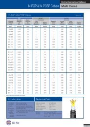
For all cable types of IN-POP, IN-POSP, IN-PIOP, IN-PIOSP & IN-EOP, IN-EOSP, IN-EIOP, IN-EIOSP<br />
IN-POP, IN-POSP, IN-PIOP, IN-PIOSP & IN-EOP, IN-EOSP, IN-EIOP, IN-EIOSP Technical Table 15<br />
1. Test Voltage : 1000 Vr.m.s. for 1 minute between each conducor in turn and all the other connected together<br />
2. Maximum DC Conductor Resistance at 20°C<br />
Conductor Size Multi-cores Multi-pairs<br />
0.5 mm 2 39.0 39.7<br />
0.75 mm 2 26.0 26.5<br />
1.0 mm 2 18.1 18.4<br />
1.5 mm 2 12.1 12.3<br />
3. Minimum Insulation Resistance at 20°C<br />
PE Insulated PVC Insulated<br />
Individual Conductor (between) each conductor and<br />
remaining bunched conductors/ screen and/ or armour 5000 MΩikm 25 MΩikm<br />
Individual Screens (between screens) 1 MΩikm 1 MΩikm<br />
4. Maximum Mutual Capacitance at 1 KHz (pF/m)<br />
Cable Type Conductor Size 0.5mm 2 1.0mm 2 1.5mm 2<br />
PE Insulated <strong>Cables</strong> without individual pair screen 75 pF/m 75 pF/m 85 pF/m<br />
PE Insulated All cables with individual pair screen, 1 and 2 pair cables collective screen 115 pF/m 115 pF/m 120 pF/m<br />
PVC Insulated Pairs or adjacent cores 250 pF/m<br />
5. Maximum Capacitance Unbalance at 1 KHz<br />
PE Insulated <strong>Cables</strong> : 250 pF / 250 m<br />
PVC Insulated <strong>Cables</strong> : 450 pF / m<br />
6. Maximum L/R Ratio (For Adjacent Cores)<br />
Conductor Size<br />
Multi-cores<br />
0.5 mm 2 25 µH/Ω<br />
0.75 mm 2 25 µH/Ω<br />
1.0 mm 2 25 µH/Ω<br />
1.5 mm 2 40 µH/Ω<br />
Maximum Conductor Resistance Technical Table 16<br />
Cross Section Area (S)<br />
(mm 2 )<br />
Conductor for Fixed Wiring<br />
Class 1 (solid), Class 2 (stranded)<br />
0.50 36.0<br />
0.75 24.5<br />
1.00 18.1<br />
1.50 12.1<br />
2.50 7.41<br />
4 4.61<br />
6 3.08<br />
10 1.83<br />
16 1.15<br />
25 0.727<br />
35 0.524<br />
50 0.387<br />
70 0.268<br />
95 0.193<br />
120 0.153<br />
150 0.124<br />
185 0.0991<br />
240 0.0754<br />
300 0.0601<br />
400 0.0470<br />
500 0.0366<br />
630 0.0283<br />
800 0.0221<br />
1000 0.0176<br />
Electrical Characteristics Technical Table 17<br />
Conductor Resistance Temperature Correction Factors<br />
Temp°C<br />
Factor<br />
10 0.961<br />
11 0.965<br />
12 0.969<br />
13 0.972<br />
14 0.976<br />
15 0.980<br />
16 0.984<br />
17 0.988<br />
18 0.992<br />
19 0.996<br />
20 1.000<br />
21 1.004<br />
22 1.008<br />
23 1.012<br />
24 1.016<br />
25 1.020<br />
30 1.039<br />
35 1.059<br />
40 1.079<br />
45 1.098<br />
50 1.118<br />
55 1.138<br />
60 1.157<br />
65 1.177<br />
70 1.196<br />
75 1.216<br />
80 1.236<br />
85 1.255<br />
90 1.275<br />
39