Driveshafts for Industrial Applications - GWB
Driveshafts for Industrial Applications - GWB
Driveshafts for Industrial Applications - GWB

Create successful ePaper yourself
Turn your PDF publications into a flip-book with our unique Google optimized e-Paper software.
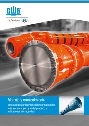
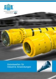
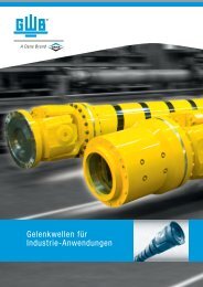
<strong>Driveshafts</strong> <strong>for</strong><br />
<strong>Industrial</strong> <strong>Applications</strong>
Table of Contents<br />
1 Dana: Driveshaft engineering experts<br />
4 Survey of <strong>GWB</strong> TM driveshaft<br />
series with design features<br />
and preferred applications<br />
8 Special designs of <strong>GWB</strong> driveshafts<br />
and additional equipment<br />
10 Notations <strong>for</strong> reviewing data sheets<br />
Data sheets<br />
12 Series 687/688<br />
16 Series 587<br />
18 Series 390<br />
20 Series 392/393<br />
22 Series 492<br />
24 Series 498<br />
26 Series 587/190 Super short designs<br />
28 Series 330 Quick release couplings<br />
29 Series 230 Quick release couplings<br />
30 Journal cross assemblies<br />
31 Flange connection with serration<br />
32 Face key connection<br />
series 687/688/587/390<br />
33 Standard companion flanges<br />
34 Design features Series 687/688/587<br />
and series 390/392/393<br />
36 General theoretical instructions<br />
38 Technical instructions <strong>for</strong> application<br />
48 Selection of <strong>GWB</strong> driveshafts<br />
51 Additional in<strong>for</strong>mation and ordering<br />
instructions<br />
52 After-sales service<br />
© Spicer Gelenkwellenbau GmbH
Dana: Driveshaft engineering experts For more than<br />
100 years, Dana’s expertise and worldwide network of manufacturing<br />
partnerships have sustained its ability to supply economically<br />
efficient, high-per<strong>for</strong>mance products to original equipment<br />
manufacturers (OEMs) in changing market environments.<br />
With a focus on technical innovation,<br />
quality per<strong>for</strong>mance, reliability,<br />
and flexibility, Dana engineers<br />
continue to provide customers<br />
with the same quality and support<br />
they’ve come to expect.<br />
Since 1946, Dana’s <strong>GWB</strong> TM driveshafts<br />
have been known <strong>for</strong> global<br />
innovation and quality per<strong>for</strong>mance.<br />
<strong>GWB</strong> heavy driveshafts<br />
were the first to be developed<br />
specifically <strong>for</strong> diesel locomotives.<br />
In the 1950s, <strong>GWB</strong> driveshafts<br />
were the largest available at that<br />
time, and were followed several<br />
decades later by the first maintenance-free<br />
driveshaft. Based on a<br />
long-standing commitment to<br />
continual innovation and customer<br />
satisfaction, <strong>GWB</strong> driveshafts<br />
have been recognized as a<br />
market leader trough-out the<br />
world.<br />
<strong>GWB</strong> driveshafts include a wide<br />
range of products <strong>for</strong> multiple applications,<br />
covering a torque range<br />
from 2.400 to 16.300.000 Nm.<br />
1<br />
© Spicer Gelenkwellenbau GmbH
Today, there are basically two types of driveshafts that have<br />
evolved into a worldwide technology standard. Their main difference<br />
lies in the design of the bearing eye.<br />
Closed bearing eye: This is a<br />
design used mainly in the commercial<br />
vehicles sector and <strong>for</strong><br />
general mechanical engineering<br />
applications (series 687/688<br />
and 587).<br />
Split bearing eye: Developed <strong>for</strong><br />
heavy and super-heavy duty<br />
applications, this design (series<br />
390/392/393 and 492/498),<br />
provides compact dimensions in<br />
conjunction with a maximum<br />
torque transmission capability<br />
and greatly improved service life,<br />
apart from facilitating maintenance<br />
and assembly operations.<br />
2.400 - 16.300.000 Nm<br />
Closed bearing eye<br />
Split bearing eye<br />
2<br />
© Spicer Gelenkwellenbau GmbH
3<br />
© Spicer Gelenkwellenbau GmbH
Survey of <strong>GWB</strong> TM driveshaft series<br />
Series<br />
687/688<br />
Torque range T CS<br />
from 2,4 to 35 kNm<br />
Flange diameter<br />
from 100 to 225 mm<br />
587<br />
Torque range T CS<br />
from 43 to 57 kNm<br />
Flange diameter<br />
from 225 to 285 mm<br />
390<br />
Maximum bearing life<br />
Torque range T CS<br />
from 60 to 255 kNm<br />
Flange diameter<br />
from 285 to 435 mm<br />
4<br />
© Spicer Gelenkwellenbau GmbH
Survey of <strong>GWB</strong> TM driveshaft series<br />
Design features<br />
Preferred applications<br />
• Closed bearing eyes<br />
• Compact design<br />
• Low maintenance<br />
• Plastic-coated splines<br />
• Operating angle up to 25°, partly up to 44°<br />
• Railway vehicles<br />
• Rolling mill plants<br />
• Marine drives<br />
• General machinery construction plants<br />
Technical data (refer to data sheets)<br />
• Closed bearing eyes<br />
• Compact design<br />
• Low maintenance<br />
• Splines coated with lubricating varnish<br />
(587.50 – plastic-coated)<br />
• Operating angle up to 24°<br />
• Railway vehicles<br />
• Rolling mill plants<br />
• Marine drives<br />
• General machinery construction plants<br />
Technical data (refer to data sheets)<br />
• Maximum bearing life in confined spaces<br />
• Split bearing eyes with toothed bearing cap<br />
• Compact design<br />
• Optimized roller bearing<br />
• Length compensation coated with lubricating<br />
varnish<br />
• Operating angle up to 15°<br />
• Railway vehicles<br />
• Marine drives<br />
• Crane systems<br />
• Paper machines<br />
• General machinery construction plants<br />
Technical data (refer to data sheets)<br />
5<br />
© Spicer Gelenkwellenbau GmbH
Survey of <strong>GWB</strong> TM driveshaft series<br />
Series<br />
392/393<br />
High torque capacity/<br />
optimized bearing life<br />
Torque range T CS<br />
from 70 to 1.150 kNm<br />
Flange diameter<br />
from 225 to 550 mm<br />
492<br />
Maximum torque capacity<br />
Torque range T CS<br />
from 210 to 1.300 kNm<br />
Flange diameter<br />
from 285 to 550 mm<br />
498<br />
Larger sizes available<br />
on request<br />
Torque range T CS<br />
from 1.880 to 15.000 kNm<br />
Flange diameter<br />
from 600 to 1.200 mm<br />
6<br />
© Spicer Gelenkwellenbau GmbH
Survey of <strong>GWB</strong> TM driveshaft series<br />
Design features<br />
Preferred applications<br />
• High torque capacity despite small connecting<br />
dimensions<br />
• Split bearing eyes with toothed bearing cap<br />
• Compact design<br />
• Journal cross with low notch factor<br />
• Length compensation coated with lubricating<br />
varnish<br />
• Operating angle 10° up to 15°<br />
• Series 393 with optimized bearing life<br />
• Rolling mill plants<br />
• Calender drives<br />
• Heavy-loaded plants of general machinery<br />
construction<br />
Technical data (refer to data sheets)<br />
• Increased torque capacity in comparison to 393<br />
• Split bearing eyes with toothed bearing cap<br />
• Standard Hirth-serrated flange<br />
• Journal cross with low notch factor<br />
• Length compensation coated with lubricant<br />
varnish<br />
• Operating angle 7° up to 15°<br />
• Rolling mill plants<br />
• Calender drives<br />
• Extremely high loaded plants of general<br />
machinery construction<br />
Technical data (refer to data sheets)<br />
• Three operating angle versions <strong>for</strong> maximum<br />
torque or maximum bearing life capacity<br />
• Split bearing eyes with toothed bearing cap<br />
• Standard Hirth-serrated flange<br />
• Operating angle up to 15°<br />
• Main rolling mill drive units<br />
• Heavy machinery construction plants<br />
Technical data (refer to data sheets)<br />
7<br />
© Spicer Gelenkwellenbau GmbH
Special designs of <strong>GWB</strong> TM driveshafts<br />
and additional equipment<br />
Series<br />
587/190 Super short designs<br />
Torque range T CS<br />
from 23 to 94 kNm<br />
Flange diameter<br />
from 275 to 405 mm<br />
392/393 Tunnel joint shafts<br />
Torque range T CS<br />
from 57 to 1.053 kNm<br />
Flange diameter<br />
from 225/315 to<br />
550/710 mm<br />
Intermediate shafts<br />
8<br />
© Spicer Gelenkwellenbau GmbH
Special designs of <strong>GWB</strong> TM driveshafts<br />
and additional equipment<br />
Design features<br />
Preferred applications<br />
• Closed bearing eyes (series 587)<br />
• Split bearing eyes (series 190)<br />
• Joints and length compensation<br />
are regreasable<br />
• Operating angle up to 5°<br />
• Railway vehicles<br />
• Rolling mill plants<br />
• Marine drives<br />
• Calender drives<br />
• Paper machines<br />
• General machinery construction plants<br />
Technical data (refer to data sheets)<br />
• Shorter designs with large length compensation<br />
• Length compensation through the joint<br />
• High torque capacity with small connection<br />
dimensions<br />
• Split bearing eyes with toothed bearing cap<br />
• Bearings with labyrinth seals<br />
• Operating angle up to 10°/ 7,5°<br />
• Rolling mill plants<br />
• With or without length compensation<br />
• Integrated bearing location<br />
• Pump drives<br />
9<br />
© Spicer Gelenkwellenbau GmbH
Notations <strong>for</strong> reviewing data sheets<br />
Standard designs<br />
0.01<br />
Driveshaft with length<br />
compensation, tubular design<br />
0.03<br />
Driveshaft without length<br />
compensation, tubular design<br />
9.01<br />
9.02<br />
9.03<br />
Driveshaft with length<br />
compensation, short design<br />
9.04<br />
Driveshaft without length<br />
compensation, double flange<br />
shaft design<br />
Special designs<br />
0.02<br />
Driveshaft with large length compensation,<br />
tubular design<br />
9.06<br />
Driveshaft with length<br />
compensation, super short<br />
design<br />
10<br />
© Spicer Gelenkwellenbau GmbH
Intermediate shafts*<br />
(available with intermediate<br />
bearing on request)<br />
0.04<br />
Intermediate shaft with length<br />
compensation<br />
0.04<br />
Intermediate shaft without length<br />
compensation<br />
0.01<br />
Midship shaft<br />
* Data sheet and / or drawing<br />
available on request.<br />
11<br />
© Spicer Gelenkwellenbau GmbH
Data sheet series 687/688<br />
0.02 with length compensation, tubular design<br />
0.03 without length compensation, tubular design<br />
9.01 with length compensation, short design<br />
9.03 with length compensation, short design<br />
9.04 without length compensation, double flange<br />
shaft design<br />
Design<br />
M<br />
L z<br />
M<br />
G<br />
∅W<br />
∅S<br />
∅K<br />
F<br />
∅A<br />
∅C<br />
b<br />
0.02<br />
Shaft size 687/688.15 687/688.20 687/688.25 687/688.30 687/688.35 687/688.40<br />
T CS kNm 2,4 3,5 5 6,5 10 14<br />
T DW kNm 0,7 1,0 1,6 1,9 2,9 4,4<br />
Lc – 1,79 x 10 –4 5,39 x 10 –4 1,79 x 10 –3 2,59 x 10 –3 0,0128 0,0422<br />
b
Data sheet series 687/688<br />
Design<br />
L f<br />
60°<br />
22,5°<br />
0.03<br />
45°<br />
L z<br />
∅B<br />
∅B<br />
9.01<br />
9.03<br />
L f<br />
∅H<br />
6-hole flange<br />
∅H<br />
8-hole flange<br />
NOTE: Hole patterns are not optional.<br />
Each driveshaft size has a specific hole pattern.<br />
9.04<br />
Design Shaft size 687/688.15 687/688.20 687/688.25 687/688.30 687/688.35 687/688.40<br />
0.02<br />
0.03<br />
9.01<br />
9.03<br />
9.04<br />
L z min mm 346 379 458 492 504 582 572 586 693 586 693<br />
L a mm 60 70 100 110 110 110 110 110 180 110 180<br />
G kg 5,7 8,4 12,0 13 14,2 24,0 25,6 28,7 30,3 29,4 30,9<br />
G R kg 3,62 4,37 5,13 6,44 6,44 7,18 7,18 8,66 10,6 8,66 10,6<br />
Jm kgm 2 0,0043 0,0089 0,0144 0,0245 0,0245 0,043 - 0,0676 0,0706 0,0776 0,0806<br />
Jm R kgm 2 0,0034 0,0059 0,0096 0,0122 0,0122 0,0169 0,0169 0,0296 0,0242 0,0296 0,0242<br />
C Nm/rad. 0,26 x 10 5 0,42 x 10 5 0,71 x 10 5 0,78 x 10 5 0,78 x 10 5 1,18 x 10 5 - 2,17 x 10 5 1,61 x 10 5 2,17 x 10 5 1,61 x 10 5<br />
C R Nm/rad. 0,34 x 10 5 0,60 x 10 5 0,98 x 10 5 1,25 x 10 5 1,25 x 10 5 1,72 x 10 5 1,72 x 10 5 3,02 x 10 5 2,47 x 10 5 3,02 x 10 5 2,47 x 10 5<br />
L f min mm 221 239 282 310 322 379 369 423 449 423 449<br />
G kg 4,1 5,8 8,6 8,6 9,8 18,0 19,6 22,8 21,0 23,4 21,6<br />
Jm kgm 2 0,0038 0,0085 0,0129 0,0238 0,0238 0,04 - 0,066 0,0628 0,076 0,0728<br />
C Nm/rad. 0,44 x 10 5 0,86 x 10 5 1,44 x 10 5 1,74 x 10 5 1,74 x 10 5 1,81 x 10 5 - 3,35 x 10 5 2,78 x 10 5 3,35 x 10 5 2,78 x 10 5<br />
L z min mm 296 322 361 379 391 510 500 505 525 505 525<br />
L a min mm 38 41 36 36 36 70 70 70 60 70 60<br />
L z max mm 348 381 425 453 465 550 540 545 645 545 645<br />
L a max mm 90 100 100 110 110 110 110 110 180 110 180<br />
L z min mm 245 274 313 331 343 419 409 441 – 441 –<br />
L a min mm 25 27 28 29 29 45 45 45 – 45 –<br />
L z max mm 280 317 355 397 409 484 474 506 – 506 –<br />
L a max mm 60 70 70 95 95 110 110 110 – 110 –<br />
L f min mm 192 216 280 288 312 380 360 408 408 408 408<br />
L z min = Shortest possible compressed length<br />
L a = Length compensation<br />
L f min = Shortest fi xed length<br />
L z + L a = Maximum operating length<br />
G<br />
G R<br />
Jm<br />
Jm R<br />
= Weight of shaft<br />
= Weight per 1.000 mm tube<br />
= Moment of inertia<br />
= Moment of inertia per 1.000 mm tube<br />
C<br />
C R<br />
= Torsional stiffness of shaft without tube<br />
= Torsional stiffness per 1.000 mm tube<br />
13<br />
© Spicer Gelenkwellenbau GmbH
Data sheet series 687/688<br />
0.02 with length compensation, tubular design<br />
0.03 without length compensation, tubular design<br />
9.01 with length compensation, short design<br />
9.03 with length compensation, short design<br />
9.04 without length compensation, double flange<br />
shaft design<br />
Design<br />
M<br />
L z<br />
M<br />
G<br />
∅W<br />
∅S<br />
∅K<br />
F<br />
∅A<br />
∅C<br />
b<br />
0.02<br />
Shaft size<br />
T CS<br />
kNm<br />
T DW<br />
kNm<br />
Lc –<br />
b
Data sheet series 687/688<br />
Design<br />
L f<br />
22,5°<br />
36°<br />
0.03<br />
45°<br />
L z<br />
∅B<br />
∅B<br />
9.01<br />
9.03<br />
∅H<br />
8-hole flange<br />
∅H<br />
10-hole flange<br />
L f<br />
NOTE: Hole patterns not optional.<br />
Each driveshaft size has a specific hole pattern.<br />
9.04<br />
Design Shaft size 687/688.45 687/688.55 687/688.65<br />
0.02<br />
0.03<br />
9.01<br />
9.03<br />
9.04<br />
L z min mm 595 703 585 662 681 622 686 686<br />
L a mm 110 180 110 110 110 110 110 110<br />
G kg 35,7 38,4 37,7 44,0 49,2 47,0 60,6 64,6<br />
G R kg 11,44 12,95 11,44 16,86 16,86 16,86 20,12 20,12<br />
Jm kgm 2 0,1002 0,1242 0,1342 0,131 – 0,151 0,2224 0,2614<br />
Jm R kgm 2 0,0385 0,0357 0,0385 0,055 – 0,055 0,0932 0,0932<br />
C Nm/rad. 3,10 x 10 5 2,18 x 10 5 3,10 x 10 5 4,05 x 10 5 – 4,05 x 10 5 5,63 x 10 5 5,63 x 10 5<br />
C R Nm/rad. 3,93 x 10 5 3,65 x 10 5 3,93 x 10 5 5,60 x 10 5 5,60 x 10 5 5,60 x 10 5 9,50 x 10 5 9,50 x 10 5<br />
L f min mm 425 425 415 475 495 435 491 491<br />
G kg 28,0 27,8 30 33,1 – 36,1 47,3 51,3<br />
Jm kgm 2 0,0954 0,0976 0,1294 0,1176 – 0,1376 0,2032 0,2422<br />
C Nm/rad. 4,82 x 10 5 3,71 x 10 5 4,82 x 10 5 5,39 x 10 5 – 5,39 x 10 5 7,17 x 10 5 7,17 x 10 5<br />
L z min mm 517 538 507 587 606 547 601 601<br />
L a min mm 70 60 70 70 70 70 70 70<br />
L z max mm 557 658 547 617 636 577 641 641<br />
L a max mm 110 180 110 100 100 100 110 110<br />
L z min mm 447 – 437 513 – 473 524 524<br />
L a min mm 50 – 50 50 – 50 50 50<br />
L z max mm 507 – 497 563 – 523 584 584<br />
L a max mm 110 – 110 110 – 110 110 110<br />
L f min mm 380 380 360 460 460 380 440 440<br />
L z min = Shortest possible compressed length<br />
L a = Length compensation<br />
L f min = Shortest fi xed length<br />
L z + L a = Maximum operating length<br />
G<br />
G R<br />
Jm<br />
Jm R<br />
= Weight of shaft<br />
= Weight per 1.000 mm tube<br />
= Moment of inertia<br />
= Moment of inertia per 1.000 mm tube<br />
C<br />
C R<br />
= Torsional stiffness of shaft without tube<br />
= Torsional stiffness per 1.000 mm tube<br />
15<br />
© Spicer Gelenkwellenbau GmbH
Data sheet series 587<br />
0.01 with length compensation, tubular design<br />
0.02 with large length compensation, tubular design<br />
0.03 without length compensation, tubular design<br />
9.01 with length compensation, short design<br />
9.02 with length compensation, short design<br />
9.03 with length compensation, short design<br />
9.04 without length compensation, double flange<br />
shaft design<br />
Design<br />
M<br />
L z<br />
M<br />
G<br />
∅W<br />
∅S<br />
∅K<br />
0.01<br />
587.55<br />
587.60<br />
∅A<br />
∅C<br />
F<br />
b<br />
0.02<br />
587.50<br />
Shaft size<br />
T CS<br />
kNm<br />
T DW<br />
kNm<br />
Lc –<br />
b
Data sheet series 587<br />
Design<br />
L f<br />
Standard flange connection<br />
38°<br />
22,5°<br />
22,5°<br />
0.03<br />
45°<br />
45°<br />
48°<br />
L z<br />
9.01<br />
9.02<br />
9.03<br />
∅B<br />
∅B s<br />
∅B<br />
L f<br />
∅H<br />
∅H<br />
∅Hs<br />
9.04<br />
8-hole flange<br />
8-hole flange<br />
Dowel pin connection according to DIN 15451<br />
Design Shaft size 587.50 587.55 587.60<br />
0.01<br />
0.02*<br />
L z min mm – – 840 840 870<br />
L a mm – – 100 100 100<br />
G kg – – 120 125 132<br />
G R kg – – 38,2 38,2 38,2<br />
Jm kgm 2 – – 0,657 0,737 0,950<br />
Jm R kgm 2 – – 0,239 0,239 0,239<br />
C Nm/rad. – – 8,7 x 10 5 8,7 x 10 5 9,6 x 10 5<br />
C R Nm/rad. – – 24,3 x 10 5 24,3 x 10 5 24,3 x 10 5<br />
L z min mm 800 800 960 960 990<br />
L a min mm 110 110 200 200 200<br />
G kg 86 91 157 162 170<br />
G R kg 23,7 23,7 38,2 38,2 38,2<br />
Jm kgm 2 0,325 0,361 - - -<br />
Jm R kgm 2 0,111 0,111 0,239 0,239 0,239<br />
0.03<br />
9.01<br />
9.02<br />
9.03<br />
9.04<br />
C Nm/rad. 5,29 x 10 5 5,29 x 10 5 - - -<br />
C R Nm/rad. 11,33 x 10 5 11,33 x 10 5 24,3 x 10 5 24,3 x 10 5 24,3 x 10 5<br />
L f mm 540 540 610 610 640<br />
G kg 72 77 90 95 103<br />
G R kg 23,7 23,7 38,2 38,2 38,2<br />
Jm kgm 2 0,270 0,306 0,547 0,627 0,84<br />
Jm R kgm 2 0,111 0,111 0,239 0,239 0,239<br />
C Nm/rad. 7,2 x 10 5 7,2 x 10 5 9,8 x 10 5 9,8 x 10 5 11,5 x 10 5<br />
C R Nm/rad. 11,33 x 10 5 11,33 x 10 5 24,3 x 10 5 24,3 x 10 5 24,3 x 10 5<br />
L z min mm – – 815 815 843<br />
L a mm – – 100 100 100<br />
G kg – – 110 115 142<br />
Jm kgm 2 – – 0,64 0,72 0,93<br />
C Nm/rad. – – 8,8 x 10 5 8,8 x 10 5 9,7 x 10 5<br />
L z mm – – 780 780 810<br />
L a mm – – 65 65 70<br />
G kg – – 108 113 125<br />
L z mm 550 600 650 696 550 600 650 696 720 720 750<br />
L a mm 60 75 90 110 60 75 90 110 65 65 65<br />
G kg 61 66 68 70 66 71 73 75 113 118 126<br />
L f mm 432 432 500 500 540<br />
G kg 58 68 81 91 110<br />
L z min = Shortest possible compressed length<br />
L a = Length compensation<br />
L f min = Shortest fi xed length<br />
L z + L a = Maximum operating length<br />
G<br />
G R<br />
Jm<br />
Jm R<br />
= Weight of shaft<br />
= Weight per 1.000 mm tube<br />
= Moment of inertia<br />
= Moment of inertia per 1.000 mm tube<br />
C = Torsional stiffness of shaft without tube<br />
C R = Torsional stiffness per 1.000 mm tube<br />
* Larger length compensation available on request<br />
17<br />
© Spicer Gelenkwellenbau GmbH
Data sheet series 390 Maximum bearing life<br />
0.01 with length compensation, tubular design<br />
0.02 with large length compensation, tubular design<br />
0.03 without length compensation, tubular design<br />
9.01 with length compensation, short design<br />
9.02 with length compensation, short design<br />
9.03 with length compensation, short design<br />
9.04 without length compensation, double flange<br />
shaft design<br />
Design<br />
G<br />
M<br />
L z<br />
M<br />
∅A<br />
∅C<br />
∅W<br />
∅S<br />
∅K<br />
F<br />
0.01<br />
Shaft size<br />
T CS<br />
kNm<br />
T DW<br />
kNm<br />
Lc –<br />
b
Data sheet series 390 Maximum bearing life<br />
Design<br />
L z<br />
L z<br />
0.02<br />
9.01<br />
9.02<br />
9.03<br />
L f<br />
L f<br />
0.03 9.04<br />
Standard<br />
flange<br />
connection<br />
38°<br />
22,5°<br />
45°<br />
18°<br />
36°<br />
Dowel pin connection<br />
according<br />
to DIN 15451<br />
22,5°<br />
45°<br />
48°<br />
18°<br />
36°<br />
36°<br />
∅B<br />
∅B<br />
∅B s<br />
∅B<br />
∅B s<br />
∅B<br />
∅H<br />
∅H<br />
∅H<br />
∅Hs<br />
∅H<br />
∅Hs<br />
8-hole flange<br />
10-hole flange<br />
8-hole flange<br />
10-hole flange<br />
NOTE: Each driveshaft size has a specific hole<br />
pattern (see table). Other hole patterns available on request.<br />
Design Shaft size 390.60 390.65 390.70 390.75 390.80<br />
0.01<br />
0.02*<br />
0.03<br />
9.01<br />
9.02<br />
9.03<br />
9.04<br />
L z min mm 870 980 1.070 1.210 1.280<br />
L a mm 100 135 135 170 170<br />
G kg 138 216 276 405 490<br />
G R kg 38,2 45,0 67,5 74,8 119<br />
Jm kgm 2 1,04 1,61 2,51 4,20 8,20<br />
Jm R kgm 2 0,239 0,494 0,716 1,28 1,93<br />
C Nm/rad. 1,0 x 10 6 1,65 x 10 6 2,43 x 10 6 3,3 x 10 6 4,7 x 10 6<br />
C R Nm/rad. 2,43 x 10 6 5,04 x 10 6 7,3 x 10 6 1,3 x 10 7 1,96 x 10 7<br />
L z min mm 990 1.080 1.170 1.295 1.365<br />
L a min mm 200 220 220 250 250<br />
G kg 178 280 337 508 586<br />
G R kg 38,2 45,0 67,5 74,8 119<br />
L f min mm 640 710 800 890 960<br />
G kg 109 159 218 302 385<br />
G R kg 38,2 45,0 67,5 74,8 119<br />
L z mm 843 953 1.043 1.175 1.245<br />
L a mm 100 135 135 170 170<br />
G kg 136 213 273 402 482<br />
L z mm 810 890 980 1.100 1.170<br />
L a mm 70 75 75 95 95<br />
G kg 135 198 261 375 456<br />
L z mm 750 835 925 1.030 1.100<br />
L a mm 65 75 75 85 85<br />
G kg 135 202 264 371 453<br />
L f mm 540 600 680 760 840<br />
G kg 108 146 210 284 380<br />
L z min = Shortest possible compressed length<br />
L a = Length compensation<br />
L f min = Shortest fi xed length<br />
L z + L a = Maximum operating length<br />
G<br />
G R<br />
Jm<br />
Jm R<br />
= Weight of shaft<br />
= Weight per 1.000 mm tube<br />
= Moment of inertia<br />
= Moment of inertia per 1.000 mm tube<br />
C = Torsional stiffness of shaft without tube<br />
C R = Torsional stiffness per 1.000 mm tube<br />
* Larger length compensation available on request<br />
19<br />
© Spicer Gelenkwellenbau GmbH
Data sheet series 392/393 High torque capacity<br />
0.01 with length compensation, tubular design<br />
0.02 with large length compensation, tubular design<br />
0.03 without length compensation, tubular design<br />
9.01 with length compensation, short design<br />
9.02 with length compensation, short design<br />
9.03 with length compensation, short design<br />
9.04 without length compensation, double flange<br />
shaft design<br />
Design<br />
M<br />
L z<br />
M<br />
G<br />
F<br />
∅A<br />
∅C<br />
∅W<br />
∅S<br />
∅K<br />
b<br />
X<br />
0.01<br />
Y<br />
Shaft size<br />
T CS<br />
kNm<br />
T DW<br />
kNm<br />
Lc –<br />
b
45°<br />
Data sheet series 392/393 High torque capacity<br />
Design<br />
L z<br />
0.02<br />
L f<br />
38°<br />
22,5°<br />
Flange connection with face key<br />
15°<br />
30°<br />
10°<br />
20°<br />
0.03<br />
∅B<br />
∅B<br />
∅B<br />
L z<br />
9.01<br />
9.02<br />
9.03<br />
∅H<br />
8-hole flange<br />
∅H<br />
10-hole flange<br />
∅H<br />
16-hole flange<br />
9.04<br />
L f<br />
Each driveshaft size has a specific<br />
hole pattern (see table). Other<br />
hole patterns available on request.<br />
Design Shaft size 392.50 392.55 392.60 392.65 392.70 393.75 393.80 393.85 393.90<br />
0.01<br />
0.02*<br />
0.03<br />
9.01<br />
9.02<br />
9.03<br />
9.04<br />
L z min mm 890 1.010 1.090 1.240 1.310 1.430 1.620 1.820 2.035<br />
L a mm 100 135 135 170 170 170 170 190 210<br />
G kg 129 214 272 406 493 732 1.055 1.477 2.209<br />
G R kg 38,2 45 67,5 74,8 119 210,4 255,6 311,3 401,1<br />
Jm kgm 2 1,02 1,43 2,23 3,80 6,5 11,72 17,84 25,26 40,76<br />
Jm R kgm 2 0,239 0,494 0,716 1,28 1,93 3,02 5,38 7,87 13,3<br />
C Nm/rad. 9,5 x 10 5 1,42 x 10 6 2,36 x 10 6 3,1 x 10 6 4,4 x 10 6 5,19 x 10 6 7,86 x 10 6 1,09 x 10 7 1,43 x 10 7<br />
C R Nm/rad. 2,43 x 10 6 5,06 x 10 6 7,3 x 10 6 1,3 x 10 7 1,96 x 10 7 3,08 x 10 7 5,48 x 10 7 8,03 x 10 7 1,36 x 10 8<br />
L z min mm 1.010 1.110 1.190 1.325 1.395 1.570 1.780 1.975 2.190<br />
L a min mm 200 220 220 250 250 310 330 350 365<br />
G kg 171 275 331 515 603 796 1.158 1.648 2.367<br />
G R kg 38,2 45 67,5 74,8 119 210,4 255,6 311,3 401,1<br />
L f min mm 660 740 820 920 990 977 1.110 1.240 1.380<br />
G kg 101 156 215 301 389 538 748 1.052 1.600<br />
G R kg 38,2 45 67,5 74,8 119 210,4 255,6 311,3 401,1<br />
L z mm 863 983 1.063 1.205 1.275 1.363 1.550 1.750 1.955<br />
L a mm 100 135 135 170 170 170 170 190 210<br />
G kg 130 210 269 402 487 718 1.037 1.446 2.177<br />
L z mm 830 920 1.000 1.130 1.200 1.300 1.400 1.630 1.770<br />
L a mm 70 75 75 95 95 90 90 100 100<br />
G kg 124 204 263 375 466 641 876 1.325 1.717<br />
L z mm 770 865 945 1.060 1.130 1.200 1.300 1.520 1.680<br />
L a mm 65 75 75 85 85 70 70 150 80<br />
G kg 123 197 260 371 457 602 832 1.000 1.657<br />
L f mm 580 660 720 820 900 820 940 1.060 1.160<br />
G kg 94 145 207 288 391 485 653 890 1.443<br />
L z min = Shortest possible compressed length<br />
L a = Length compensation<br />
L f min = Shortest fi xed length<br />
L z + L a = Maximum operating length<br />
G<br />
G R<br />
Jm<br />
Jm R<br />
= Weight of shaft<br />
= Weight per 1.000 mm tube<br />
= Moment of inertia<br />
= Moment of inertia per 1.000 mm tube<br />
C = Torsional stiffness of shaft without tube<br />
C R = Torsional stiffness per 1.000 mm tube<br />
* Larger length compensation available on request<br />
21<br />
© Spicer Gelenkwellenbau GmbH
Data sheet series 492 Maximum torque capacity<br />
0.01 with length compensation, tubular design<br />
0.03 without length compensation, tubular design<br />
9.01 with length compensation, short design<br />
9.02 with length compensation, short design<br />
9.03 with length compensation, short design<br />
9.04 without length compensation, double flange<br />
shaft design<br />
Design<br />
G<br />
M<br />
L z<br />
∅A<br />
∅W<br />
∅S<br />
∅K<br />
M<br />
0.01<br />
Shaft size 492.60 492.65 492.70 492.75 492.80 492.85 492.90<br />
T CS kNm 210 250 340 440 410 650 580 850 770 1.300 1.170<br />
T DW kNm 100 115 160 210 190 280 250 400 360 600 540<br />
Lc – 107 332 860 2.060 7.390 17.400 60.120<br />
b
Data sheet series 492 Maximum torque capacity<br />
Design<br />
L f<br />
Flange connection with Hirth-serration<br />
36°<br />
30°<br />
22,5°<br />
0.03<br />
L z<br />
∅B<br />
∅B<br />
∅B<br />
9.01<br />
9.02<br />
9.03<br />
∅H<br />
∅H<br />
∅H<br />
L f<br />
10-hole flange<br />
12-hole flange<br />
16-hole flange<br />
9.04<br />
Each driveshaft size has a specific<br />
hole pattern (see table). Other<br />
hole patterns available on request.<br />
Design Shaft size 492.60 492.65 492.70 492.75 492.80 492.85 492.90<br />
0.01<br />
0.03<br />
9.01<br />
9.04<br />
L z min mm 1.440 1.520 1.680 1.750 1.900 2.130 2.415<br />
L a mm 135 135 150 170 170 190 210<br />
G kg 472 568 788 1.025 1.355 1.873 2.750<br />
G R kg 121 149 180 255,6 311,3 361,4 501,94<br />
Jm kgm 2 4,16 5,16 7,73 15 30,7 50,4 92,7<br />
Jm R kgm 2 1,52 1,78 2,69 5,38 7,88 12,28 21,1<br />
C Nm/rad. 3,32 x 10 6 4,31 x 10 6 5,97 x 10 6 6,76 x 10 6 9,7 x 10 6 13,64 x 10 6 19,44 x 10 6<br />
C R Nm/rad. 1,55 x 10 7 1,82 x 10 7 2,75 x 10 7 5,48 x 10 7 8,03 x 10 7 12,51 x 10 7 21,5 x 10 7<br />
L f min mm 940 1.020 1.130 1.220 1.320 1.450 1.620<br />
G kg 311 407 557 819 1.040 1.330 1.880<br />
G R kg 121 149 180 255,6 311,3 361,4 501,9<br />
L z mm 1.380 1.460 1.620 1.700 1.840 2.050 2.340<br />
L a mm 135 135 150 170 170 190 210<br />
G kg 465 559 777 1.010 1.340 1.850 2.710<br />
L f mm 800 880 960 1.040 1.120 1.200 1.320<br />
G kg 286 374 514 780 1.000 1.300 1.830<br />
L z min = Shortest possible compressed length<br />
L a = Length compensation<br />
L f min = Shortest fi xed length<br />
L z + L a = Maximum operating length<br />
G<br />
G R<br />
Jm<br />
Jm R<br />
= Weight of shaft<br />
= Weight per 1.000 mm tube<br />
= Moment of inertia<br />
= Moment of inertia per 1.000 mm tube<br />
C<br />
C R<br />
= Torsional stiffness of shaft without tube<br />
= Torsional stiffness per 1.000 mm tube<br />
Length dimensions (L z /L a ) of the designs 0.02 · 9.02 · 9.03 available on request.<br />
23<br />
© Spicer Gelenkwellenbau GmbH
Data sheet series 498<br />
0.01 with length compensation, tubular design<br />
0.03 without length compensation, tubular design<br />
9.04 without length compensation, double flange<br />
shaft design<br />
Design<br />
M<br />
L z<br />
M<br />
G<br />
∅A<br />
∅K<br />
0.01<br />
Shaft size 498.00 498.05 498.10 498.15<br />
T CS kNm 1.880 1.620 1.430 2.340 2.080 1.750 3.000 2.600 2.200 3.640 3.100 2.700<br />
T DW kNm 900 780 680 1.120 1.000 840 1.430 1.250 1.050 1.750 1.500 1.300<br />
Lc – 0,115 0,144 0,154 0,224 0,322 0,343 0,530 0,684 0,720 1,09 1,35 1,43<br />
x 10 6 x 10 6 x 10 6 x 10 6 x 10 6 x 10 6 x 10 6 x 10 6 x 10 6 x 10 6 x 10 6 x 10 6<br />
b
Data sheet series 498<br />
Design<br />
L f<br />
Flange connection with Hirth-serration<br />
18°<br />
15°<br />
0.03<br />
L f<br />
∅B<br />
∅B<br />
9.04<br />
∅H<br />
20-hole flange<br />
∅H<br />
24-hole flange<br />
Each driveshaft size has a specific<br />
hole pattern (see table). Other<br />
hole patterns available on request.<br />
Shaft size 498.40 498.45 498.50 498.55 498.60<br />
T CS kNm 8.700 7.500 6.500 10.000 8.700 7.500 11.500 10.000 8.600 13.200 11.400 9.900 15.000 13.000 11.200<br />
T DW kNm 4.200 3.600 3.100 4.800 4.200 3.600 5.500 4.800 4.100 6.300 5.500 4.700 7.200 6.200 5.400<br />
Lc – 16,1 17,4 23,78 24,4 28,71 38,73 36,4 42,63 61,67 56,3 70,8 96,19 89,9 102 147,2<br />
x 10 6 x 10 6 x 10 6 x 10 6 x 10 6 x 10 6 x 10 6 x 10 6 x 10 6 x 10 6 x 10 6 x 10 6 x 10 6 x 10 6 x 10 6<br />
b
Data sheet series 587/190 Super short designs<br />
9.06 driveshaft with length compensation,<br />
super short design<br />
Series 587<br />
Design<br />
M<br />
L z<br />
M<br />
36°<br />
G<br />
∅B<br />
∅A<br />
∅C<br />
∅W<br />
∅K<br />
F<br />
36°<br />
9.06<br />
∅H<br />
10-hole flange<br />
Shaft size 587.50 190.55 190.60 190.65 190.70<br />
T CS kNm 43 33 48 68 130<br />
T DW kNm 13 11 21 25 53<br />
Lc – 1,84 7,0 58,5 166 510<br />
b
Data sheet series 587/190 Super short designs<br />
Series 190<br />
Design<br />
M<br />
L z<br />
M<br />
36°<br />
G<br />
∅A<br />
∅C<br />
∅K<br />
F<br />
∅W<br />
∅B<br />
b<br />
36°<br />
9.06<br />
∅H<br />
10-hole flange<br />
Design Shaft size 587.50 190.55 190.60 190.65 190.70<br />
9.06<br />
L z mm 415 495 545 600 688<br />
L a mm 40 40 40 40 55<br />
G kg 60 98 120 169 256<br />
Jm kgm 2 0,33 0,624 1,179 2,286 3,785<br />
L z = Shortest compressed length<br />
L a = Length compensation<br />
L z + L a = Maximum operating length<br />
G<br />
Jm<br />
= Weight of shaft<br />
= Moment of inertia<br />
27<br />
© Spicer Gelenkwellenbau GmbH
Data sheet series 330 Quick release couplings<br />
Design<br />
with spiral serration <strong>for</strong> higher speeds<br />
∅A<br />
∅B<br />
∅C<br />
K<br />
L<br />
F<br />
G<br />
F k<br />
∅Ck<br />
SW<br />
Connection <strong>for</strong> series 687/688<br />
Connection <strong>for</strong> series 587<br />
Connection <strong>for</strong> series 392<br />
with face key<br />
D<br />
For hole distribution, see data<br />
sheets of the corresponding<br />
driveshaft.<br />
Coupling size 330.10 330.20 330.30 330.40 330.50 330.55<br />
Shaft connection<br />
687/688.25 687/688.30 687/688.40 687/688.55<br />
687/688.15 687/688.20 687/688.45 587.50 392.50 587.55 392.55<br />
687/688.35 687/688.40 687/688.45 687/688.65<br />
Model Nr. 000 003 003 003 000 001 000 001<br />
A mm 100 130 150 180 225 225 250 250<br />
B mm 84 101,5 130 155,5 196 196 218 218<br />
C 1 ) mm 57 75 90 110 140 105 140 105<br />
C 11 k ) mm 57 75 90 110 140 105 140 105<br />
D 2 ) mm 20 38 40 40 45 45 45 45<br />
F mm 2,5 2,5 3,5 4 5 5 6 6<br />
F k mm 2,3–0,2 2,3–0,15 2,3–0,2 2,3–0,15 4–0,2 4–0,2 5–0,2 5–0,2<br />
G mm 76 100 100 112 144 144 148 162<br />
I 3 ) – 6 8 8 8 8 8 8 8<br />
K 4 ) – M 8 x 18 M 10 x 22 M 12 x 25 M 14 x 28 M 16 x 35 M 16 x 40 M 18 x 40 M 18 x 45<br />
L 10 ) mm 10 11 14 20 18 18 21 21<br />
G 12 k ) kg 4,7 7,5 10,6 16,4 34 36 40 49<br />
Ta Nut Nm 35 69 120 190 295 295 405 405<br />
Extension 5 ) Nr. 2.365/13 M 2.365/17 M 2.365/19 M 22 M 24 R 24 R 27 R 27 R<br />
Ta Spindle Nm 30 45 80 100 190 190 220 220<br />
Socket wrench 6 )<br />
Nr.<br />
1 / 2“ D 19 SW 13<br />
1 / 2“ D 19 SW 17<br />
1 / 2“ D 19 SW 22<br />
Operating instructions<br />
Engaging and disengaging the coupling<br />
Engaging and disengaging are done by operating the threaded<br />
spindle located in the inner part of the coupling. The<br />
spindle can be reached from two sides and be operated. The<br />
spindle is tightened by means of a socket wrench (see table).<br />
Notice:<br />
1. Be<strong>for</strong>e engaging the coupling, make sure that the coupling<br />
teeth are properly fitted.<br />
2. The engagement direction is marked by arrows. The<br />
spindle may be tightened either clockwise or counterclockwise.<br />
3. The joint with the coupling component falls back when<br />
disengaged. Caution: Danger of injury!<br />
In case of a subsequent installation of the quick release<br />
coupling, the driveshaft must be correspondingly shorter.<br />
The threaded spindles of the coupling are lubricated by the<br />
supplier with MoS 2 . Relubrication is recommended from<br />
time to time.<br />
28<br />
© Spicer Gelenkwellenbau GmbH
Data sheet series 230 Quick release couplings<br />
Design<br />
with trapezoidal serration <strong>for</strong> speeds up to 1.000 rpm<br />
G<br />
F k<br />
K<br />
L<br />
F<br />
SW<br />
Connection <strong>for</strong> series 390<br />
Connection <strong>for</strong> series 392/393<br />
with face key<br />
∅A<br />
∅B<br />
∅C<br />
∅Ck<br />
For hole distribution, see data<br />
sheets of the corresponding<br />
driveshaft.<br />
D<br />
Coupling size 230.60 230.65 230.70 230.75 230.80<br />
Shaft connection 390.60 392.60 390.65 392.65 390.70 392.70 390.75 393.75 390.80 393.80<br />
Model Nr. 000 001 000 001 000 001 000 001 000 001<br />
A mm 285 285 315 315 350 350 390 390 435 435<br />
B mm 245 245 280 280 310 310 345 345 385 385<br />
C 1 ) mm 175 125 175 130 220 155 250 170 280 190<br />
C 11 k ) mm 175 125 175 130 220 155 250 170 280 190<br />
D 2 ) mm 64 64 66 66 72 72 82 82 92 92<br />
F mm 7 7 7 8 8 8 8 8 10 10<br />
F k mm 6–0,2 6–0,5 6–0,2 7–0,5 7–0,3 7–0,5 7–0,2 7–0,5 9–0,5 9–0,5<br />
G mm 160 174 172 192 184 204 196 220 226 246<br />
I 3 ) – 8 8 8 10 10 10 10 10 10 16<br />
K 4 ) – M 20 x 45 M 20 x 55 M 22 x 50 M 22 x 60 M 22 x 50 M 22 x 60 M 24 x 55 M 24 x 70 M 27 x 65 M 27 x 75<br />
L 10 ) mm 23 23 25 25 25 25 27 27 30 30<br />
G 12 k ) kg 66 71 83 95 110 120 143 150 210 230<br />
Ta Nut Nm 580 580 780 780 780 780 1.000 1.000 1.500 1.500<br />
Extension 5 ) Nr. 30 R 30 R 32 R 32 R 32 R 32 R 36 R 36 R 41 R 41 R<br />
Ta Spindle Nm 290 290 400 400 550 550 680 680 950 9 ) 950 9 )<br />
Socket wrench 6 )<br />
Nr.<br />
3 / 4“ D 32 SW 22<br />
3 / 4“ D 32 SW 27<br />
3 / 4“ D 32 SW 27<br />
3 / 4“ D 32 SW 32<br />
3 / 4“ D 32 SW 36<br />
X = 4 spanners 8 ) Nr. -<br />
TD 750<br />
1. Spigot fit H7<br />
2. Disengaging movement <strong>for</strong> separation of the coupling<br />
3. Number of stud bolts per flange<br />
4. Dimensions of the bolt connections<br />
Stud bolt DIN 938<br />
Self-locking hexagon nut DIN 980<br />
5. Jaw or ring extension in accordance with Dana standard N 4.2.5<br />
6. Gedore socket spanner set <strong>for</strong> tightening the spindle<br />
7. Rahsol torque meter<br />
8. Force multiplier spanner x = 4 (TD 750)<br />
9. Adjusting moment of the torque wrench 756 C = 238 Nm<br />
10. Thread depth<br />
11. Fit h6 up to series 390<br />
Fit f8 <strong>for</strong> series 392/393<br />
12. Gk = Weight of coupling<br />
Ta = Tightening torques of flange boltings and of the<br />
threaded coupling spindles<br />
Torque wrench 7 )<br />
Torque range<br />
Type<br />
from<br />
to<br />
756 B<br />
20 Nm 100 Nm<br />
756 C<br />
80 Nm 300 Nm<br />
756 D<br />
280 Nm 760 Nm<br />
For applications with speeds higher than 1.000 rpm, please contact Dana<br />
engineers. Other designs available on request.<br />
29<br />
© Spicer Gelenkwellenbau GmbH
Data sheet Journal cross assemblies (unit packs)<br />
Design<br />
7.06 journal cross, complete<br />
B<br />
∅A<br />
∅ A<br />
B<br />
Shaft size<br />
mm<br />
mm<br />
473.10 15 41<br />
473.20 19 49,2<br />
473.30 22 59<br />
287.00 26 69,8<br />
287.10 30 81,8<br />
287.20 35 96,8<br />
587.10 35 96,8<br />
587.15 42 104,5<br />
587.20 48 116,5<br />
587.30 52 133<br />
587.35/36 57 144<br />
587.42 57 152,06<br />
587.48 65 172<br />
587.50 72 185<br />
587.55 74 217<br />
587.60 83 231,4<br />
687/688.15 27,0 74,5<br />
687/688.20 30,2 81,8<br />
687/688.25 34,9 92,0<br />
687/688.30 34,9 106,4<br />
687/688.35 42,0 119,4<br />
687/688.40 47,6 135,17<br />
687/688.45 52,0 147,2<br />
687/688.55 57,0 152,0<br />
687/688.65 65,0 172,0<br />
B 1<br />
B<br />
∅A<br />
Journal cross assemblies are only supplied as complete<br />
units. For orders, please state shaft size or,<br />
if known, the drawing number of the complete driveshaft.<br />
For lubrication of journal cross assemblies,<br />
see Installation and Maintenance/Safety Instructions.<br />
* The dimensions of the journal cross assemblies<br />
<strong>for</strong> series 392/393 are equal to 292.<br />
Shaft size<br />
190.50 65 220 143<br />
190.55 74 244 154<br />
190.60 83 280 175<br />
190.65 95 308 190<br />
190.70 110 340 210<br />
190.75 120 379 235<br />
190.80 130 425 262<br />
390.60 83 235,8 129<br />
390.65 95 258,8 139<br />
390.70 110 293,4 160<br />
390.75 120 325,2 176<br />
390.80 130 363,2 196<br />
392.50* 74 222 129<br />
392.55* 83 246 139<br />
392.60* 95 279,6 160<br />
392.65* 110 309,6 176<br />
392.70* 120 343,4 196<br />
393.75* 130 383,4 216<br />
393.80* 154 430 250<br />
393.85* 170 464 276<br />
393.90* 195 530 315<br />
Ultra heavy-duty unit pack<br />
sets <strong>for</strong> series 398 have been<br />
discontinued.<br />
∅ A B B 1<br />
mm mm mm<br />
They are still available <strong>for</strong> series<br />
492 and 498 on request.<br />
30<br />
© Spicer Gelenkwellenbau GmbH
Data sheet Flange connection with serration<br />
Hirth-serration<br />
• Flank angle 40°<br />
• High transmission capacity<br />
• Form locking<br />
• Self-centering<br />
∅D<br />
∅d<br />
∅B<br />
D d z B i*<br />
mm mm mm<br />
225 180 48 200 8 x M 12<br />
250 200 48 225 8 x M 14<br />
285 225 60 255 10 x M 14<br />
315 250 60 280 10 x M 16<br />
350 280 72 315 12 x M 16<br />
390 315 72 350 12 x M 18<br />
435 345 96 395 16 x M 18<br />
480 370 96 445 16 x M 20<br />
550 440 96 510 16 x M 22<br />
600 480 120 555 20 x M 24<br />
650 520 120 605 20 x M 24<br />
700 570 120 655 24 x M 24<br />
750 600 144 695 24 x M 30<br />
800 650 144 745 24 x M 30<br />
850 680 144 785 24 x M 36<br />
900 710 144 835 24 x M 36<br />
950 760 144 885 24 x M 36<br />
1.000 800 180 925 20 x M 42 x 3<br />
1.050 840 180 975 20 x M 42 x 3<br />
1.100 880 180 1.025 20 x M 42 x 3<br />
1.150 925 180 1.065 20 x M 48 x 3<br />
1.200 960 180 1.115 20 x M 48 x 3<br />
Klingelnberg-serration<br />
• Flank angle 25°<br />
• High transmission capacity<br />
• Form locking<br />
• Self-centering<br />
∅D<br />
∅d<br />
∅B<br />
D d z B i<br />
mm mm mm<br />
95 65 16 84 4 x M 8<br />
115 80 24 101,5 4 x M 10<br />
145 110 24 130 4 x M 12<br />
175 140 32 155,5 4 x M 16<br />
215 175 48 196 4 x M 16<br />
240 195 48 218 4 x M 18<br />
275 220 48 245 4 x M 20<br />
305 245 48 280 4 x M 20<br />
340 280 72 310 4 x M 22<br />
380 315 72 345 6 x M 24<br />
425 355 96 385 6 x M 27<br />
465 390 96 425 8 x M 30<br />
535 455 96 492 8 x M 30<br />
D = Outside diameter<br />
d = Inside diameter<br />
Z = Number of teeth<br />
B = Pitch diameter<br />
i = Number and size of bolts<br />
Bolt material: 10.9<br />
* Reduced number of bolts by special<br />
arrangement only (e.g., <strong>for</strong> use as quickchange<br />
system)<br />
Other diameters available on request.<br />
31<br />
© Spicer Gelenkwellenbau GmbH
Data sheet Face key connection series 687/688/587/390<br />
The driveshaft <strong>for</strong> series 687/688/587/390 can also be manufactured<br />
with face key connection on request.<br />
∅A<br />
X<br />
Y<br />
Series 687/688<br />
∅A<br />
∅A<br />
X<br />
Y<br />
Series 587<br />
X<br />
Y<br />
Series 390<br />
Driveshaft connection<br />
∅ A<br />
Shaft size I 2 ) x H 1 )<br />
X e9 Y<br />
mm mm mm<br />
687/688.35<br />
687/688.40<br />
150 8 x 13 20 4,0<br />
687/688.45 8 x 15<br />
687/688.55 180 10 x 17 25 4,5<br />
687/688.65 10 x 17<br />
587.50 225 8 x 17 32 5,5<br />
587.55 250 8 x 19 40 7,0<br />
587.60 285 8 x 21 45 8,0<br />
390.60 285 8 x 21 45 8,0<br />
390.65 315 8 x 23 45 8,0<br />
390.70 350 10 x 23 50 9,0<br />
390.75 390 10 x 25 50 9,0<br />
390.80 435 10 x 28 63 12,0<br />
1. Tolerance + 0,2 mm<br />
(<strong>for</strong> 390.75 and 390.80,<br />
tolerance + 0,5 mm)<br />
2. Number of flange holes<br />
32<br />
© Spicer Gelenkwellenbau GmbH
Data sheet Standard companion flanges<br />
Standard companion flanges can be manufactured with cylindrical<br />
bore holes and face keyway (material C45; hardened<br />
and tempered 750 – 900 N/mm 2 ) on request. For designs<br />
deviating from the standard, e.g., oil pressure connection,<br />
conical bore, flat journal, and material, relevant drawings are<br />
required.<br />
u<br />
∅A<br />
∅Z<br />
L 1<br />
∅D<br />
∅d<br />
v<br />
∅H<br />
L<br />
Please state with your order:<br />
Shaft size =<br />
Flange dia. A =<br />
mm<br />
I x H = number of holes x ∅ mm<br />
L = mm<br />
L 1 = mm<br />
Z = mm<br />
D = mm<br />
d = mm<br />
u = mm<br />
v = mm<br />
Driveshaft connection<br />
Dimension<br />
Shaft size<br />
∅ A<br />
I 2 ) x H 1 )<br />
∅ D max<br />
mm<br />
mm<br />
687/688.15<br />
100 6 x 8,25 69,5<br />
687/688.20<br />
687/688.15<br />
687/688.20<br />
120 8 x 10,25 84<br />
687/688.25<br />
687/688.30<br />
687/688.25<br />
8 x 12,25<br />
687/688.30<br />
150<br />
8 x 12,25<br />
110,3<br />
687/688.35<br />
687/688.40<br />
687/688.35<br />
687/688.40<br />
8 x 12,1<br />
8 x 12,1<br />
8 x 14,1<br />
687/688.45<br />
180 132,5<br />
687/688.55<br />
10 x 16,1<br />
687/688.65<br />
687/688.45<br />
687/688.55<br />
225 8 x 16,1 171<br />
687/688.65<br />
587.50<br />
587.50<br />
250 8 x 18,1 189<br />
587.55<br />
587.60<br />
285 8 x 20,1 213<br />
390.60<br />
390.65<br />
315 8 x 22,1 247<br />
390.70<br />
350 10 x 22,1 277<br />
390.75<br />
390 10 x 24,1 308<br />
390.80<br />
435 10 x 27,1 342<br />
1. Tolerance + 0,2 mm<br />
(<strong>for</strong> 390.75 and 390.80,<br />
tolerance + 0,5 mm)<br />
2. Number of flange holes<br />
33<br />
© Spicer Gelenkwellenbau GmbH
Design features series 687/688/587<br />
1<br />
5<br />
4<br />
2<br />
3<br />
6<br />
2<br />
1<br />
7<br />
Main components of the driveshafts<br />
1. Flange yoke<br />
2. Journal cross assembly<br />
3. Tube yoke<br />
4. Tube<br />
5. Sliding muff<br />
6. Yoke shaft<br />
7. Cover tube assembly<br />
34<br />
© Spicer Gelenkwellenbau GmbH
Design features series 390/392/393<br />
1a<br />
2<br />
4<br />
5<br />
3<br />
7<br />
2<br />
1a<br />
6<br />
1b<br />
Main components of the driveshafts<br />
1a. Flange yoke <strong>for</strong> series 390<br />
(friction connection)<br />
1b. Flange yoke <strong>for</strong> series 392/393<br />
(face key connection)<br />
2. Journal cross assembly<br />
3. Tube yoke<br />
4. Tube<br />
5. Tube yoke with sliding muff<br />
6. Slip stub shaft<br />
7. Cover tube assembly<br />
35<br />
© Spicer Gelenkwellenbau GmbH
General theoretical instructions<br />
Kinematics of Hooke’s joints<br />
1. The joints<br />
In the theory of mechanics, the<br />
cardan joint (or Hooke’s joint)<br />
is defined as a spatial or spherical<br />
drive unit with a non-uni<strong>for</strong>m<br />
gear ratio or transmission. The<br />
transmission behavior of this joint<br />
is described by the following<br />
equation:<br />
a 2 = arc tan 1 · tan<br />
(<br />
a 1<br />
cosb )<br />
1<br />
b<br />
2<br />
90°<br />
b = Deflection angle of joint [
General theoretical instructions<br />
The following diagram shows the<br />
ratio i = ω 2 /ω 1 <strong>for</strong> a full revolution<br />
of the universal joint <strong>for</strong> b = 60°.<br />
The degree of non-uni<strong>for</strong>mity U is<br />
defined by:<br />
U = i max. – i min. = tanb · sinb<br />
Where:<br />
i<br />
2<br />
1,5<br />
1<br />
0,5<br />
i max. =<br />
1<br />
cosb<br />
i min. = cosb<br />
0<br />
p/2 p 3p/2 2p<br />
a 1<br />
Angular difference ϕ K max.<br />
10°<br />
1<br />
9°<br />
0,9<br />
8°<br />
0,8<br />
7°<br />
0,7<br />
6°<br />
0,6<br />
ϕ K max.<br />
5°<br />
0,5<br />
4°<br />
0,4<br />
3°<br />
0,3<br />
2°<br />
U<br />
0,2<br />
1°<br />
0,1<br />
0°<br />
0°<br />
0° 5° 10° 15° 20° 25° 30° 35° 40° 45°<br />
Deflection angle b<br />
Degree of non-uni<strong>for</strong>mity U<br />
The diagram shows the course of<br />
the degree of non-uni<strong>for</strong>mity U and<br />
of the angular difference ϕ K max. as<br />
a function of the deflection angle<br />
of the joint from 0 to 45°.<br />
From the motion equation it is<br />
evident that a homokinematic<br />
motion behavior corresponding<br />
to the dotted line under 45° – as<br />
shown in the diagram – can only<br />
be obtained <strong>for</strong> the deflection<br />
angle b = 0°. A synchronous or<br />
homokinematic running can be<br />
achieved by a suitable combination<br />
or connection of two or<br />
more joints.<br />
37<br />
© Spicer Gelenkwellenbau GmbH
Technical instructions <strong>for</strong> application<br />
2. The driveshaft<br />
The rotation angle difference ϕ K<br />
or the gimbal error of a deflected<br />
universal joint can be offset under<br />
certain installation conditions<br />
with a second universal joint.<br />
The constructive solutions are the<br />
following:<br />
1. The deflection angles of both<br />
joints must be equal (i.e., b 1 = b 2 )<br />
Two arrangements are possible:<br />
1a) Z-deflection<br />
1b) W- or M-deflection<br />
b 1<br />
b 2<br />
b 1<br />
b 2<br />
2. The two joints must have a<br />
kinematic angular relationship<br />
of 90° (p/2), (i.e., the yokes of<br />
the connecting shaft are in one<br />
plane).<br />
For a more intensive study of<br />
universal shaft kinematics, please<br />
refer to the VDI-recommendation<br />
2722 and to the relevant technical<br />
literature.<br />
Operating angles<br />
The most common arrangements<br />
are the Z- and W-deflections. To<br />
begin, consider the system in<br />
which the shafts to be connected<br />
are in the same plane.<br />
Z-arrangement<br />
b 1<br />
b 2<br />
W-arrangement<br />
b 1 b 2<br />
Maximum permissible angle<br />
difference<br />
The condition b 1 = b 2 is one of<br />
the essential requirements <strong>for</strong> a<br />
uni<strong>for</strong>m output speed condition<br />
and cannot always be fulfilled.<br />
There<strong>for</strong>e, designers and engineers<br />
will often ask <strong>for</strong> the permissible<br />
difference between the<br />
deflection angles of both joints.<br />
The deflection angles <strong>for</strong> hightorque<br />
and high-speed machine<br />
drives should be equal. If not, the<br />
difference should be limited to<br />
1° to 1,5°.<br />
38<br />
© Spicer Gelenkwellenbau GmbH
Technical instructions <strong>for</strong> application<br />
Product of speed and deflection<br />
angle<br />
Greater differences of about<br />
3° to 5° are acceptable without<br />
disadvantages in low-speed<br />
applications. For applications<br />
with varying deflection conditions,<br />
it is important to obtain<br />
uni<strong>for</strong>mity, if possible over the<br />
complete deflection range.<br />
Deflection in two planes means<br />
that the deflection is both horizontal<br />
and vertical. The combination<br />
of two identical types<br />
of deflection (Z/Z or W/W) and<br />
identical deflection angles ensure<br />
uni<strong>for</strong>mity. For a combination of<br />
Z- and W-deflection, the inner<br />
yokes must be offset. Please<br />
consult with Dana application<br />
engineers to determine the proper<br />
amount of angular offset.<br />
Determination of the maximum<br />
permissible operating deflection<br />
angle<br />
Depending on the driveshaft<br />
series, the maximum deflection<br />
angle per joint is b = 5° to 44°.<br />
Due to the kinematic conditions<br />
of the cardan joint, as described<br />
be<strong>for</strong>e, the deflection angle must<br />
be limited in relation to the speed.<br />
Calculations and observations of<br />
many applications have shown<br />
that certain mass acceleration<br />
torques of the center part must<br />
not be exceeded in order to<br />
guarantee smooth running of the<br />
drive systems. This acceleration<br />
torque depends on the<br />
D = n .<br />
and the moment of inertia of the<br />
middle part of the shaft. The<br />
parameter D is proportional to<br />
the angular acceleration of the<br />
driveshaft center part ε 2 .<br />
ε<br />
2 ~ D = n . b<br />
n = Operating speed [rpm]<br />
b = Deflection angle of joint [
Technical instructions <strong>for</strong> application<br />
Limits <strong>for</strong> the product of operating speed and deflection angle<br />
687/688.15-20<br />
687/688.25<br />
687/688.30-35<br />
34°<br />
32°<br />
30°<br />
687/688.40<br />
687/688.45<br />
687/688.55<br />
390.60 | 392.50 | 587.50-55-60 | 687/688.65<br />
390.65-70-75-80 | 392.55-60-65-70<br />
28°<br />
26°<br />
24°<br />
22°<br />
Deflection angle b<br />
20°<br />
18°<br />
16°<br />
14°<br />
12°<br />
10°<br />
8°<br />
6°<br />
4°<br />
2°<br />
0°<br />
0 500 1.000 1.500 2.000 2.500 3.000 3.500 4.000 4.500 5.000<br />
Speed n [rpm]<br />
40<br />
© Spicer Gelenkwellenbau GmbH
Technical instructions <strong>for</strong> application<br />
Speed<br />
Checking the critical torsional<br />
speed<br />
The plant or vehicle manufacturer<br />
has to prevent the use of driveshafts<br />
within the critical torsional<br />
speed ranges of the drive.<br />
There<strong>for</strong>e, the determination of<br />
the critical torsional speed ranges<br />
of the drive system is required.<br />
The values <strong>for</strong> the moment of inertia<br />
and torsional stiffness of the<br />
selected driveshaft can be taken<br />
from the data sheets or be<br />
supplied upon request.<br />
Checking the critical bending<br />
speed<br />
Except <strong>for</strong> short and rigid designs,<br />
driveshafts are flexible units<br />
with critical bending speeds and<br />
flexural vibrations that have to<br />
be checked. To accomplish this,<br />
the first and possibly second<br />
order critical bending speeds are<br />
important.<br />
For safety reasons, the maximum<br />
permissible operating speed<br />
must be at a sufficient distance<br />
from the critical bending speed.<br />
The diameter is limited because<br />
of the ratio to the shaft size.<br />
There<strong>for</strong>e, single driveshafts can<br />
only be provided up to a certain<br />
length. All installations exceeding<br />
this limit have to be equipped with<br />
subdivided drive lines.<br />
For determination of the critical<br />
bending speed, see the<br />
following selection diagrams.<br />
These diagrams only apply to<br />
driveshafts that are installed with<br />
solid bearing supports located<br />
close to the flange.<br />
Different installations (e.g.,<br />
units with elastic mounting<br />
bearing) must have lower critical<br />
bending speeds.<br />
Depending on the type of the<br />
plant, excitations of second<br />
order can cause flexible vibrations.<br />
Please contact Dana<br />
engineers if the deflection<br />
angle exceeds 3° and <strong>for</strong> greater<br />
length dimensions.<br />
n perm. max. _~ 0,8 · n crit. [rpm]<br />
The critical bending speed <strong>for</strong><br />
a particular shaft size is determined<br />
by the length and the tube<br />
diameter only (see diagram). For<br />
greater length dimensions, the<br />
tube diameter has to be increased.<br />
41<br />
© Spicer Gelenkwellenbau GmbH
Technical instructions <strong>for</strong> application<br />
Series 687/688<br />
Determination of the critical bending speed depending on the respective operating length<br />
687/688.15 - 63,5 x 2,4<br />
687/688.20 - 76,2 x 2,4<br />
687/688.25 - 89 x 2,4<br />
687/688.30 - 90 x 3<br />
687/688.35 - 100 x 3<br />
687/688.40 - 100 x 4,5<br />
687/688.40 - 120 x 3<br />
687/688.45 - 120 x 4<br />
687/688.55 - 120 x 6<br />
687/688.45 - 110 x 5<br />
687/688.65 - 142 x 6<br />
Example: 687.15 – 63,5 x 2,4<br />
Joint size 687.15<br />
Tube outer diameter 63,5 mm<br />
Wall thickness 2,4 mm<br />
6.000<br />
5.500<br />
5.000<br />
M 2M<br />
M<br />
L B<br />
2M<br />
Critical bending speed ncrit. [rpm]<br />
4.500<br />
4.000<br />
3.500<br />
3.000<br />
2.500<br />
2.000<br />
1.500<br />
1.000<br />
1.000 1.500 2.000 2.500 3.000<br />
Operating length L B [mm]<br />
42<br />
© Spicer Gelenkwellenbau GmbH
Technical instructions <strong>for</strong> application<br />
Series 587/390/392<br />
Determination of the critical bending speed depending on the respective operating length<br />
587.50 - 144 x 7<br />
587.55 - 168,8 x 7,3<br />
587.60/392.50/390.60 - 167,7 x 9,8<br />
392.55/390.65 - 218,2 x 8,7<br />
392.60/390.70 - 219 x 13,3<br />
392.65/390.75 - 273 x 11,6<br />
392.70/390.80 - 273 x 19 Example: 390.60 – 167,7 x 9,8<br />
Joint size 390.60<br />
Tube outer diameter 167,7 mm<br />
Wall thickness 9,8 mm<br />
6.000<br />
5.500<br />
5.000<br />
M<br />
L B<br />
2M<br />
Critical bending speed ncrit. [rpm]<br />
4.500<br />
4.000<br />
3.500<br />
3.000<br />
2.500<br />
2.000<br />
1.500<br />
1.000<br />
2.000 2.500 3.000 3.500 4.000 4.500 5.000 5.500 6.000 6.500 7.000<br />
Operating length L B [mm]<br />
43<br />
© Spicer Gelenkwellenbau GmbH
Technical instructions <strong>for</strong> application<br />
Length dimensions<br />
The operating length of a driveshaft<br />
is determined by:<br />
• the distance between the driving<br />
and the driven units<br />
• the length compensation during<br />
operation<br />
The following abbreviations are<br />
used:<br />
L z = Compressed length<br />
This is the shortest length of the<br />
shaft. A further compression is<br />
not possible.<br />
L a = Length compensation<br />
The driveshaft can be expanded<br />
by this amount. An expansion<br />
beyond that dimension is not<br />
permissible.<br />
L z + L a = Maximum permissible<br />
operating<br />
length L Bmax.<br />
L z<br />
L B max = L z + L a<br />
During operation, the driveshaft<br />
can be expanded up to this length.<br />
The optimum working length L B<br />
of a driveshaft is achieved if the<br />
length compensation is extracted<br />
by one-third of its length.<br />
L B = L z +<br />
1<br />
L a [mm]<br />
3<br />
This general rule applies to most<br />
of the arrangements. For applications<br />
where larger length alterations<br />
are expected, the operating<br />
length should be chosen in such<br />
a way that the movement will be<br />
within the limit of the permissible<br />
length compensation.<br />
Arrangements of driveshafts<br />
A tandem arrangement of driveshafts<br />
could become necessary<br />
to cope with greater installation<br />
lengths.<br />
Driveshaft with intermediate shaft<br />
Driveshaft with two intermediate shafts<br />
Basic <strong>for</strong>ms of shaft combinations:<br />
Two driveshafts with double intermediate bearing<br />
44<br />
© Spicer Gelenkwellenbau GmbH
Technical instructions <strong>for</strong> application<br />
In such arrangements, the individual<br />
yoke positions and deflection<br />
angles should be adjusted<br />
with regard to one another in<br />
such a way that the degree of<br />
non-uni<strong>for</strong>mity (see General<br />
theoretical instructions) and the<br />
reaction <strong>for</strong>ces acting on the<br />
connection bearings (see Technical<br />
instructions <strong>for</strong> application)<br />
are minimized.<br />
Load on bearings of the connected<br />
units<br />
Axial <strong>for</strong>ces<br />
For the design of a driveshaft, it<br />
must be taken into account that<br />
axial <strong>for</strong>ces can occur. These<br />
<strong>for</strong>ces must be absorbed by axial<br />
thrust bearings of the connected<br />
units.<br />
1. Frictional <strong>for</strong>ce F RL<br />
This is the <strong>for</strong>ce that occurs<br />
in the length compensation.<br />
It can be determined from:<br />
m<br />
F RL = T · · cos b<br />
r m<br />
F RL = Frictional <strong>for</strong>ce from the<br />
length compensation [N]<br />
It depends on:<br />
T = Torque of the driveshaft<br />
[Nm]<br />
r m = Pitch circle radius in the<br />
sliding parts of the driveshaft<br />
[m]<br />
m = Friction coefficient (depends<br />
on spline treatment):<br />
• 0,08 <strong>for</strong> plastic-coated<br />
splines<br />
• 0,11 <strong>for</strong> steel/steel (greased)<br />
b = Operating deflection angle<br />
Axial <strong>for</strong>ces will occur during<br />
length variations in the driveshaft.<br />
Additional axial <strong>for</strong>ces are<br />
caused by increasing torque and<br />
by increasing pressure during<br />
lubrication of the splines. These<br />
<strong>for</strong>ces will decrease automatically<br />
and can be accelerated by the<br />
installation of a relief valve.<br />
2. Power F p<br />
This <strong>for</strong>ce occurs in the length<br />
compensation due to the increasing<br />
pressure in the lubrication<br />
grooves of the driveshaft.<br />
The <strong>for</strong>ce depends on the lubrication<br />
pressure (maximum permissible<br />
pressure is 15 bar).<br />
The axial <strong>for</strong>ce A k is a combination<br />
of two components:<br />
Dana’s environmental protection management policy<br />
An important feature of Dana’s environmental protection<br />
management policy is dedication to product responsibility.<br />
Because of this commitment, the effect of driveshafts on the<br />
environment is given considerable attention. <strong>GWB</strong> TM driveshafts<br />
are lubricated with lead-free grease, their paint finishes<br />
are low in solvents and free of heavy metals, and they are<br />
easy to maintain. After use, they can be introduced into the<br />
recycling process.<br />
45<br />
© Spicer Gelenkwellenbau GmbH
Technical instructions <strong>for</strong> application<br />
Calculation scheme of radial <strong>for</strong>ces on connecting bearings<br />
Driveshaft in Z-arrangement<br />
Position 0°, flange yoke right-angled to drawing<br />
plane, Position p/2, flange yoke in drawing plane<br />
Driveshaft in W-arrangement<br />
Position 0°, flange yoke right-angled to drawing<br />
plane, Position p/2, flange yoke in drawing plane<br />
L<br />
L<br />
T<br />
b 1<br />
b 2<br />
T<br />
b 1 b 2<br />
a = 0°<br />
B 1 F 1<br />
A 1 E 1<br />
a = 90°<br />
A 2 F 2<br />
B<br />
a 2<br />
b e E 2 f<br />
a = 0°<br />
B 1 F 1<br />
A 1 E 1<br />
a = 90°<br />
A 2<br />
F 2<br />
B<br />
a 2 E<br />
b<br />
2<br />
e f<br />
a = 0°<br />
A<br />
cosb 1 · b<br />
1 = T · · (tanb 1 - tanb 2 )<br />
L · a<br />
cosb 1 (a + b)<br />
B 1 = T · · (tanb 1 - tanb 2 )<br />
L · a<br />
a = 0°<br />
A<br />
cosb 1 · b<br />
1 = T · · (tanb 1 + tanb 2 )<br />
L · a<br />
cosb 1 (a + b)<br />
B 1 = T · · (tanb 1 + tanb 2 )<br />
L · a<br />
cosb 1 · e<br />
F 1 = T · · (tanb 1 - tanb 2 )<br />
L · f<br />
cosb 1 · (e + f)<br />
E 1 = T · · (tanb 1 - tanb 2 )<br />
L · f<br />
cosb 1 · e<br />
F 1 = T · · (tanb 1 + tanb 2 )<br />
L · f<br />
cosb 1 · (e + f)<br />
E 1 = T · · (tanb 1 + tanb 2 )<br />
L · f<br />
a = p/2 = 90°<br />
A 2 = B 2 = T ·<br />
tanb 1<br />
a<br />
a = p/2 = 90°<br />
A 2 = B 2 = T ·<br />
tanb 1<br />
a<br />
F 2 = E 2 = T ·<br />
sinb 2<br />
f · cosb 1<br />
F 2 = E 2 = T ·<br />
sinb 2<br />
f · cosb 1<br />
Driveshaft arrangement with b 1 = b 2<br />
equal deflection angles and a = f, b = e<br />
equal bearing distances<br />
Driveshaft arrangement with b 1 = b 2<br />
equal deflection angles and a = f, b = e<br />
equal bearing distances<br />
a = 0° A 1 = F 1 = B 1 = E 1 = 0<br />
a = 0° A 1 = F 1 = 2T ·<br />
sinb 1 · b<br />
L · a<br />
a = p/2 = 90° A tanb 2 = B 2 = T · 1<br />
sinb 1 (a<br />
a<br />
B + b)<br />
1 = E 1 = 2T ·<br />
L · a<br />
F 2 = E 2 = T · tanb 1<br />
a<br />
a = p/2 = 90° See Z-arrangement a = p/2<br />
46<br />
© Spicer Gelenkwellenbau GmbH
Technical instructions <strong>for</strong> application<br />
Balancing of driveshafts<br />
The balancing of driveshafts<br />
is per<strong>for</strong>med to equalize eccentrically<br />
running masses, there<strong>for</strong>e<br />
preventing vibrations and reducing<br />
the load on any connected<br />
equipment.<br />
Balancing is carried out in<br />
accordance with ISO Standard<br />
1940, “Balance quality of rotating<br />
rigid bodies”. According to this<br />
standard, the permissible residual<br />
unbalance is dependent on the<br />
operating speed and mass of the<br />
balanced components.<br />
Dana’s experience has shown<br />
that balancing is not normally<br />
required <strong>for</strong> rotational speeds<br />
below 500 rpm. In individual<br />
cases, this range may be extended<br />
or reduced, depending on<br />
the overall drivetrain characteristics.<br />
<strong>Driveshafts</strong> are balanced in two<br />
planes, normally to a balancing<br />
accuracy between G16<br />
and G40.<br />
• Balancing speed<br />
The balancing speed is normally<br />
the maximum speed of<br />
the system or vehicle.<br />
• Quality grade<br />
In defining a quality grade, it<br />
is necessary to consider the<br />
reproducibility levels achievable<br />
in the customer’s own test<br />
rig during verification testing.<br />
Quality grades are dependent<br />
on the following variables:<br />
• Type of balancing machine<br />
(hard, rigid or soft<br />
suspension)<br />
• Accuracy of the measuring<br />
system<br />
• Mounting tolerances<br />
• Joint bearing radial and<br />
axial play<br />
• Angular backlash in longitudinal<br />
displacement direction<br />
Field analyses have shown that<br />
the sum of these factors may<br />
result in inaccuracies of up to<br />
100 %. This observation has given<br />
rise to the definition of the following<br />
balancing quality grades:<br />
• Producer balancing: G16<br />
• Customer verification tests:<br />
G32<br />
G 40<br />
Car wheels, wheel rims, wheel sets, driveshafts<br />
Crankshaft/drives of elastically mounted, fast four-cycle<br />
Engines (gasoline or diesel) with six or more cylinders<br />
Crankshaft/drives of engines of cars, trucks, and locomotives<br />
G 16<br />
<strong>Driveshafts</strong> (propeller shafts, cardan shafts) with special requirements<br />
Parts of crushing machines and agricultural machinery<br />
Individual components of engines (gasoline or diesel) <strong>for</strong> cars, trucks, and locomotives<br />
Crankshaft/drives of engines with six or more cylinders under special requirements<br />
G 6,3<br />
Parts of process plant machines<br />
Marine main turbine gears (merchant service)<br />
Fans, flywheels, centrifuge drums<br />
Paper machinery rolls, print rolls<br />
Assembled aircraft gas turbine rotors<br />
Pump impellers<br />
G 2,5<br />
Gas and steam turbines, including marine main turbines (merchant service)<br />
Rigid turbo-generator rotors<br />
Turbo-compressors, turbine-driven pumps<br />
Machine tool drives<br />
Computer memory drums and discs<br />
Extract from DIN ISO 1940/Part 1<br />
47<br />
© Spicer Gelenkwellenbau GmbH
Selection of <strong>GWB</strong> TM driveshafts<br />
The design of driveshafts must<br />
exclude all possible danger<br />
to people and material by<br />
secured calculation and test<br />
results, as well as other suitable<br />
steps (see Installation and<br />
Maintenance/Safety Instructions).<br />
The selection procedure described<br />
on these pages is only<br />
a general recommendation.<br />
Please consult Dana engineers<br />
<strong>for</strong> the final design <strong>for</strong> your<br />
application.<br />
The selection of a driveshaft<br />
should be based on the following<br />
conditions:<br />
1. Specifications of driveshafts<br />
2. Selection by bearing life<br />
3. Operational dependability<br />
4. Operating angles<br />
5. Speed<br />
6. Length dimensions<br />
7. Load on bearings of the<br />
connected units<br />
1. Specifications of driveshafts<br />
T CS = Functional limit<br />
torque [Nm]<br />
Up to this maximum permissible<br />
torque, a load may be applied to<br />
a driveshaft <strong>for</strong> a limited frequency<br />
without the working capability<br />
being affected by permanent<br />
de<strong>for</strong>mation of any driveshaft<br />
functional area. This does not<br />
result in any unpermissible effect<br />
on bearing life.<br />
Yield torque<br />
This torque level leads to irreversible<br />
plastic de<strong>for</strong>mation of the<br />
driveshaft which could result in<br />
a failure of the complete drive<br />
system.<br />
T DW = Reversing fatigue<br />
torque [Nm]<br />
At this torque, the driveshaft is<br />
permanently solid at alternating<br />
loads. The values <strong>for</strong> driveshafts<br />
of series 687/688 with welded<br />
balancing plates are lower. With<br />
a fatigue torque of this order, the<br />
transmission capacity of the flange<br />
connection must be checked.<br />
T DSch = Pulsating fatigue<br />
torque [Nm]<br />
At this torque, the driveshaft is<br />
permanently solid at pulsating<br />
loads.<br />
T DSch = 1,4 · T DW<br />
L C = Bearing capacity factor<br />
The bearing capacity factor takes<br />
into consideration the dynamic<br />
service life C dyn (see DIN/ISO<br />
281) of the bearings and the joint<br />
geometry R. The L C values <strong>for</strong> the<br />
different shaft sizes are shown in<br />
the tables (see data sheets).<br />
When selecting driveshafts,<br />
the bearing life and the operating<br />
strength must be considered<br />
separately. According<br />
to the load state, the reversing<br />
fatigue torque T DW or the pulsating<br />
fatigue torque T DSch<br />
must also be taken into consideration.<br />
48<br />
© Spicer Gelenkwellenbau GmbH
Selection of <strong>GWB</strong> TM driveshafts<br />
2. Selection by bearing life<br />
By bearing capacity factor L C<br />
The bearing life L h of a driveshaft<br />
depends on the bearing capacity<br />
factor and is based on the<br />
following <strong>for</strong>mula:<br />
L h =<br />
L C · 10 10<br />
n · b · T 10/3 · K 1<br />
If the desired bearing life L h is<br />
given, the joint size can be calculated<br />
by the bearing capacity<br />
factor L C .<br />
Electric motor/turbine K 1 = 1,00<br />
Gasoline engine<br />
4 cylinder and more K 1 = 1,15<br />
Diesel engine<br />
4 cylinder and more K 1 = 1,20<br />
The values shown in the tables<br />
are general values. If a flexible<br />
coupling is used, the shock factor<br />
is lower. Principally the data<br />
of the motor and/or coupling<br />
manufacturer must be observed.<br />
3. Operating dependability<br />
70 years of experience as<br />
a manufacturer of driveshafts to<br />
provide an optimal selection.<br />
Calculations are based on the<br />
peak torque T and the maximum<br />
peak torque T SP that may occur.<br />
The peak torque is determined<br />
according to the type of operation<br />
and the torque characteristic.<br />
It should be lower than the corresponding<br />
torques T DSch and T DW .<br />
T N . K = T < T DSch or T DW<br />
L C =<br />
L h · n · b · T 10/3 · K 1<br />
10 10<br />
The L C values can be taken from<br />
the tables (see data sheets).<br />
L C = Bearing capacity factor<br />
n = Operating speed [rpm]<br />
b = Operating deflection<br />
angle [
Selection of <strong>GWB</strong> TM driveshafts<br />
Typical types of torques:<br />
T<br />
Pulsating stress<br />
T < T DSch<br />
The maximum peak torque T SP is the extremely<br />
rarely occuring torque of the system (crash,<br />
emergency case).<br />
This maximum torque (T SP ) should not exceed<br />
the functional limited torque T CS of the driveshaft.<br />
Alternating stress<br />
T SP < T CS<br />
T<br />
T < T DW<br />
T SP = Maximum peak torque<br />
T N = Nominal torque<br />
T CS = Functional limit torque of<br />
the driveshaft<br />
[Nm]<br />
[Nm]<br />
[Nm]<br />
(see data sheets)<br />
Light shock load: K = 1,1 – 1,5<br />
Heavy shock load: K = 2 – 3<br />
Driven machines<br />
Driven machines<br />
Centrifugal pumps<br />
Mixers<br />
Generators (continuous load)<br />
Bucket wheel reclaimers<br />
Conveyors (continuous load)<br />
Bending machines<br />
Small ventilators<br />
Presses<br />
Machine tools<br />
Rotary drilling rigs<br />
Printing machines<br />
Locomotive secondary drives<br />
Continuous casters<br />
Medium shock load: K = 1,5 – 2<br />
Crane drives<br />
Driven machines<br />
Centrifugal pumps<br />
Generators (non-continuous load)<br />
Extra-heavy shock load: K = 3 – 5<br />
Driven machines<br />
Conveyors (non-continuous load)<br />
Continuous working roller tables<br />
Medium ventilators<br />
Medium section mills<br />
Wood handling machines<br />
Continuous slabbing and<br />
Small paper and textile machines<br />
blooming mills<br />
Pumps (multi-cylinder)<br />
Continuous heavy tube mills<br />
Compressors (multi-cylinder)<br />
Reversing working roller tables<br />
Road and bar mills<br />
Vibration conveyors<br />
Service factor K<br />
Locomotive primary drives<br />
Scale breakers<br />
Straightening machines<br />
Heavy shock load: K = 2 – 3<br />
Cold rolling mills<br />
The service factors shown in<br />
the following tables should be<br />
used as approximate values<br />
only.<br />
Driven machines<br />
Large ventilators<br />
Marine transmissions<br />
Calender drives<br />
Transport roller tables<br />
Reeling drives<br />
Blooming stands<br />
Extreme shock load: K = 5 – 10<br />
Driven machines<br />
Small pinch rolls<br />
Feed roller drives<br />
Small tube mills<br />
Wrapper roll drives<br />
Heavy paper and textile machines<br />
Plate-shears<br />
Compressors (single-cylinder)<br />
Reversing slabbing<br />
50<br />
Pumps (single-cylinder)<br />
and blooming mills<br />
© Spicer Gelenkwellenbau GmbH
Additional in<strong>for</strong>mation and ordering instructions<br />
Selection of driveshafts<br />
The selection of a <strong>GWB</strong> TM driveshaft ist determined not only by<br />
the maximum permissible torque of the shaft and the connections<br />
but also by a variety of other factors.<br />
For the exact determination and<br />
selection of driveshafts, see the<br />
Selection of <strong>Driveshafts</strong> pages in<br />
this brochure.<br />
Dana engineers can precisely<br />
calculate the correct size of the<br />
shaft and joint <strong>for</strong> your application<br />
with the use of computer<br />
programs created specifically<br />
<strong>for</strong> this purpose.<br />
In order to best match your requirements,<br />
you’ll be asked to<br />
provide the following in<strong>for</strong>mation:<br />
• Installation length of the<br />
driveshaft<br />
• Maximum joint angle<br />
requirement<br />
• Required length compensation<br />
• Maximum rotation speed of<br />
the shaft<br />
• Shaft end connection details<br />
• Maximum torque to be<br />
transmitted<br />
• Nominal torque to be<br />
transmitted<br />
• Load occurrences<br />
• Description of the equipment<br />
and working conditions<br />
Specific applications<br />
<strong>Driveshafts</strong> in railway<br />
transmissions<br />
The selection of driveshafts in<br />
the secondary system of railway<br />
vehicles must be based on the<br />
maximum torque that can be<br />
transmitted to the track (wheel<br />
slip or adhesion torque).<br />
<strong>Driveshafts</strong> in crane travel<br />
drives<br />
The particular operating conditions<br />
<strong>for</strong> travel drives of cranes<br />
have been taken into consideration<br />
in the DIN-standard 15 450.<br />
As a result, driveshafts <strong>for</strong><br />
these applications can be selected<br />
by using that standard.<br />
<strong>Driveshafts</strong> in marine<br />
transmissions<br />
These driveshafts are subject to<br />
acceptance and must correspond<br />
to the standards of the<br />
respective classification society.<br />
<strong>Driveshafts</strong> <strong>for</strong> other <strong>for</strong>ms of<br />
passenger conveyance<br />
<strong>Driveshafts</strong> used in amusement<br />
park equipment, ski lifts or similar<br />
lift systems, elevators, and rail<br />
vehicles must be in accordance<br />
with the standards and specifications<br />
of the appropriate licensing<br />
and supervisory authorities.<br />
<strong>Driveshafts</strong> in explosive environments<br />
(Atex-outline)<br />
For the use of driveshafts in areas<br />
with danger of explosion, an<br />
EC-con<strong>for</strong>mity certificate acc. to<br />
EC-outline 94/9/EG can be<br />
provided.<br />
The possible categories <strong>for</strong> the<br />
product „driveshaft“ are:<br />
a) in general: II 3 GDc T6<br />
b) <strong>for</strong> driveshafts with adapted<br />
features: II 2 GDc T6<br />
The driveshaft should not be<br />
used under the following operating<br />
conditions:<br />
• Within the critical bending<br />
speed range of the drive<br />
• Within the critical torsional<br />
speed range of the drive<br />
• At operating angles which exceed<br />
the specified maximum<br />
(refer to drawing confirmed<br />
with order)<br />
• At dynamic and static operating<br />
torques which exceed the<br />
specified limit (refer to drawing<br />
confirmed with order)<br />
• At speed x deflection angle<br />
(n x b) conditions which<br />
exceed the limit (refer to<br />
<strong>GWB</strong> catalogue)<br />
• For usage time which exceeds<br />
the calculated bearing lifetime<br />
of the joint bearings<br />
If you’d like more in<strong>for</strong>mation<br />
on <strong>GWB</strong> driveshafts, or would<br />
like to discuss specific application<br />
requirements with an<br />
engineer, please call Dana at<br />
00 49 (0) 201- 81 24 - 0 or visit<br />
www.gwbdriveshaft.com,<br />
www.dana.com.<br />
51<br />
© Spicer Gelenkwellenbau GmbH
After-sales service Spicer Gelenkwellenbau GmbH<br />
E-mail: industrial @ dana.com, Web: www.gwbdriveshaft.com / www.dana.com<br />
Mailing address: P.O. Box 10 13 62 - 45013 Essen / Germany<br />
Office address: 2. Schnieringstraße 49 - 45329 Essen / Germany<br />
Phone: 0049 (0) 201- 81 24 - 0, Fax: 00 49 (0) 201- 81 24 - 652<br />
Home Country<br />
GKN Service International GmbH<br />
D-22525 Hamburg<br />
Ottensener Str. 150<br />
Phone: 0 40-540 090-0<br />
Fax: 0 40-540 090-44<br />
Foreign Country<br />
Argentina<br />
Chilicote S.A.<br />
Avda. Julio A. Roca 546<br />
C1067ABN - Buenos Aires<br />
Phone: 00 54-11-43 31-66 10<br />
Fax: 00 54-11-43 31-42 78<br />
E-mail: chilicote@chilicote.com.ar<br />
Also responsible <strong>for</strong> Uruguay and Chile.<br />
Australia<br />
Hardy Spicer Company P/L<br />
1/9 Monterey Road<br />
Dandenong South, Victoria 3175<br />
Phone: 00 61-3-97 941 900<br />
Fax: 00 61-3-97 069 928<br />
E-mail: russell.plowman@hardyspicer.com.au<br />
Dana Australia Pty Ltd<br />
39- 45 Wedgewood Road<br />
Hallam, Victoria, 3803<br />
Phone: 00 61-3-92 135 555<br />
Fax: 00 61-3-92 135 588<br />
www.dana.com.au<br />
Austria<br />
GKN Service Austria GmbH<br />
Slamastraße 32<br />
A-1230 Wien<br />
Phone: 00 43-1-61 63 880-0<br />
Fax: 00 43-1-61 63 880-15<br />
Also responsible <strong>for</strong> Eastern Europe.<br />
Belgium<br />
GKN Service Benelux BV<br />
Rue Emile Pathéstraat 410<br />
B-1190 Brussel (Vorst-Forest)<br />
Phone: 00 32-2-33 49 861<br />
Fax: 00 32-2-33 49 888<br />
Brazil<br />
KTB do Brasil<br />
Belo Horizonte<br />
Rua Goncalves Dias 880, 2° andar<br />
Savassi-Cep 30140-091<br />
Contact: Dhenilson Ferreira Costa<br />
Phone: 00 55-31 32 618 399<br />
E-mail: d.costa@KTB-brasil.com<br />
Web: www.KTB-brasil.com<br />
KTB do Brasil<br />
Campinas<br />
Av. Brasil 460, Sala 61<br />
Cep 13.020-460<br />
Contact: Sandro Lassala<br />
Phone: 00 55-19 33 815 100<br />
E-mail: s.lassala@KTB-brasil.com<br />
Web: www.KTB-brasil.com<br />
KTB do Brasil<br />
Porto Alegre<br />
Av. Nilo Peçanha 2825 sala 302<br />
Cep 91330-001 - Três Figueiras<br />
Contact: Luis Antonio Nicolazzi<br />
Phone: 00 55-51 21 111 020<br />
E-mail: l.nicolazzi@KTB-brasil.com<br />
Web: www.KTB-brasil.com<br />
KTB do Brasil<br />
São Paulo<br />
Rua Colatino Marques, 183<br />
Cep 04504-020<br />
Contact: Geraldo Bueno<br />
Phone: 00 55-11 38 844 360<br />
E-mail: g.bueno@KTB-brasil.com<br />
Web: www.KTB-brasil.com<br />
China / P.R.C.<br />
Dana China Shanghai Office<br />
7F, Tower B, Hongwell International Plaza<br />
No. 1602 Zhongshan Road West<br />
Xuhui District, Shanghai, China<br />
Phone: 00 86-21 333 250 00<br />
Fax: 00 86-21 648 723 00<br />
E-mail: shao.cheng@dana.com<br />
China<br />
Dana (Wuxi) Technology Co., Ltd.<br />
No. 209 Xinzhou Road, Wuxi National<br />
Hi-Technology <strong>Industrial</strong><br />
Development Zone, P.R. China<br />
Phone: 00 86-510-886 560 00<br />
Fax: 00 86-510-881 198 66<br />
Denmark<br />
GKN Service Scandinavia AB<br />
Baldershöj 11 A+B<br />
DK-2635 Ishöj<br />
Phone: 00 45-44 866 844<br />
Fax: 00 45-44 688 822<br />
Finland<br />
Oy UNILINK Ab<br />
Vattuniemenkatu 15<br />
00210 Helsinki<br />
Phone: 00 358-9-68 66 170<br />
Fax: 00 358-9-69 40 449<br />
E-mail: unilink@unilink.fi<br />
52<br />
© Spicer Gelenkwellenbau GmbH
France<br />
GKN Service France<br />
Ecoparc Cettons-Secteur 1 Jaune<br />
8 Rue Panhard et Levassor<br />
78570 Chanteloup les Vignes, France<br />
Phone: 00 33-1-30 068 434<br />
Fax: 00 33-1-30 068 439<br />
E-mail: serge.campestrini@gkn.com<br />
Greece<br />
Sokrates Mechanics GmbH<br />
205, Piraeus Str.<br />
GR-11853 Athens<br />
Phone: 00 30-210-34 71 910<br />
Fax: 00 30-210-34 14 554<br />
E-mail: sokrates@enternet.gr<br />
Hellas Cardan GmbH<br />
Strofi Oreokastrou<br />
GR-56430 Thessaloniki<br />
Phone: 00 30-2310-682 702<br />
Fax: 00 30-2310-692 972<br />
E-mail: hecardan@otenet.gr<br />
Great Britain<br />
GKN Driveline Service Ltd.<br />
Higher Woodcroft Leek,<br />
GB-Staf<strong>for</strong>dshire, ST13 5QF<br />
Phone: 00 44-15 38-384 278<br />
Fax: 00 44-15 38-371 265<br />
India<br />
Dana India Private Limited<br />
Survey No. 278, Raisoni <strong>Industrial</strong> Park, Phase II,<br />
Hinjewadi, Village-Mann, Tal. Mulshi,<br />
Pune -411 057 (INDIA)<br />
Phone: 00 91-20-30436255<br />
E-mail: sgwb.india@dana.com<br />
Netherlands<br />
GKN Service Benelux BV<br />
Haarlemmerstraatweg 155-159<br />
NL-1165 MK Halfweg<br />
Phone: 00 31-20-40 70 207<br />
Fax: 00 31-20-40 70 217<br />
Norway<br />
GKN Service Scandinavia AB<br />
Karihaugveien 102<br />
N-1086 Oslo<br />
Phone: 00 47-23 286 810<br />
Fax: 00 47-23 286 819<br />
Russia-Ukraine<br />
APA-KANDT GmbH<br />
Weidestr. 122a<br />
D-22083 Hamburg<br />
Phone: 00 49-40-48 061 438<br />
Fax: 00 49-40-480 614 938<br />
E-mail: office@apa-kandt.de<br />
Web: www.apa-kandt.de<br />
Sweden<br />
GKN Service Scandinavia AB<br />
Alfred Nobels Allé 110<br />
SE-14648 Tullinge<br />
Phone: 00 46-86 039 700<br />
Fax: 00 46-86 039 702<br />
Switzerland<br />
GKN Service International GmbH<br />
Althardstraße 141<br />
CH-8105 Regensdorf<br />
Phone: 00 41-44-871-60 70<br />
Fax: 00 41-44-871-60 80<br />
Spain<br />
Gelenk <strong>Industrial</strong> S.A.<br />
Balmes, 152<br />
E-08008 Barcelona<br />
Phone: 00 349-3-23 74 245<br />
Fax: 00 349-3-23 72 580<br />
E-mail: javier.montoya@gelenkindustrial.com<br />
South Africa<br />
Driveline Technologies (Pty) Ltd.<br />
CNR. Derrick & Newton Roads<br />
Spartan, Kempton Park<br />
P.O. Box 2649<br />
Kempton Park 1620<br />
Phone: 00 27-11-929-56 00<br />
Fax: 00 27-11-394-78 46<br />
E-mail: richard@driveline.co.za<br />
USA, Canada<br />
Dana Spicer Service Parts<br />
P.O. Box 321<br />
Toledo, OH 43697-0321<br />
Phone: 001-800-621-80 84<br />
Fax: 001-800-332-61 24<br />
E-mail: tom.deHaven@dana.com<br />
Italy<br />
Uni-Cardan Italia S.p.A.<br />
Via G. Ferraris, 125 / C<br />
I-20021 Ospiate di Bollate (MI)<br />
Phone: 00 39-02-383 381<br />
Fax: 00 39-02-33 010 30<br />
Japan<br />
Nakamura Jico Co. Ltd.<br />
10-10, Tsukiji, 3-chome<br />
Chuo-Ku, Tokyo<br />
Phone: 00 81-3-35 43-97 72<br />
Fax: 00 81-3-35 43-97 79<br />
Copyright by Spicer Gelenkwellenbau GmbH<br />
All rights reserved.<br />
Any reproduction of this publication or parts thereof is subject to the<br />
explicit authorization of the copyright-holder.<br />
This catalogue supersedes all <strong>for</strong>mer editions.<br />
We reserve the right to make alterations.<br />
Release 06/2013<br />
53<br />
© Spicer Gelenkwellenbau GmbH
Dana Holding Corporation<br />
is a world-leading supplier of driveline,<br />
sealing, and thermal-management technologies<br />
that improve the efficiency and<br />
per<strong>for</strong>mance of passenger, commercial,<br />
and off-highway vehicles with both conventional<br />
and alternative-energy powertrains.<br />
The company‘s global network<br />
of engineering, manufacturing, and<br />
distribution facilities provides originalequipment<br />
and aftermarket customers<br />
with local product and service support.<br />
Based in Maumee, Ohio, Dana employs<br />
approximately 24,500 people in 26<br />
countries and reported 2011 sales of<br />
$7.6 billion.<br />
About the Dana <strong>GWB</strong> TM Products<br />
Dana produces <strong>GWB</strong> industrial driveshafts<br />
and genuine service parts <strong>for</strong><br />
the scrap steel, construction, railway,<br />
marine, and paper industries. Manufacturing<br />
and assembly operations in<br />
Germany are supported by Dana’s<br />
global network of R&D and distribution<br />
facilities.<br />
© 2012 Dana Limited<br />
Trains <strong>Industrial</strong> plants Ships<br />
Spicer Gelenkwellenbau GmbH<br />
2. Schnieringstraße 49<br />
45329 Essen/Germany<br />
Phone: 00 49 (0) 201- 81 24 - 0<br />
Fax: 00 49 (0) 201- 81 24 - 652<br />
www.gwbdriveshaft.com<br />
www.dana.com<br />
APPLICATION POLICY<br />
Capacity ratings, features, and specifications vary depending upon the model and type of service. Application approvals must be obtained from Dana. We reserve the right to<br />
change or modify our product specifications, configurations, or dimensions at any time without notice.<br />
© Spicer Gelenkwellenbau GmbH