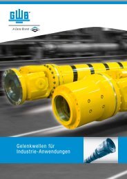
Driveshafts for Industrial Applications - GWB
Driveshafts for Industrial Applications - GWB
Driveshafts for Industrial Applications - GWB

Create successful ePaper yourself
Turn your PDF publications into a flip-book with our unique Google optimized e-Paper software.
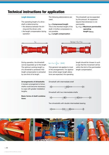
Technical instructions <strong>for</strong> application<br />
Length dimensions<br />
The operating length of a driveshaft<br />
is determined by:<br />
• the distance between the driving<br />
and the driven units<br />
• the length compensation during<br />
operation<br />
The following abbreviations are<br />
used:<br />
L z = Compressed length<br />
This is the shortest length of the<br />
shaft. A further compression is<br />
not possible.<br />
L a = Length compensation<br />
The driveshaft can be expanded<br />
by this amount. An expansion<br />
beyond that dimension is not<br />
permissible.<br />
L z + L a = Maximum permissible<br />
operating<br />
length L Bmax.<br />
L z<br />
L B max = L z + L a<br />
During operation, the driveshaft<br />
can be expanded up to this length.<br />
The optimum working length L B<br />
of a driveshaft is achieved if the<br />
length compensation is extracted<br />
by one-third of its length.<br />
L B = L z +<br />
1<br />
L a [mm]<br />
3<br />
This general rule applies to most<br />
of the arrangements. For applications<br />
where larger length alterations<br />
are expected, the operating<br />
length should be chosen in such<br />
a way that the movement will be<br />
within the limit of the permissible<br />
length compensation.<br />
Arrangements of driveshafts<br />
A tandem arrangement of driveshafts<br />
could become necessary<br />
to cope with greater installation<br />
lengths.<br />
Driveshaft with intermediate shaft<br />
Driveshaft with two intermediate shafts<br />
Basic <strong>for</strong>ms of shaft combinations:<br />
Two driveshafts with double intermediate bearing<br />
44<br />
© Spicer Gelenkwellenbau GmbH