Driveshafts for Industrial Applications - GWB
Driveshafts for Industrial Applications - GWB
Driveshafts for Industrial Applications - GWB

You also want an ePaper? Increase the reach of your titles
YUMPU automatically turns print PDFs into web optimized ePapers that Google loves.
Technical instructions <strong>for</strong> application<br />
In such arrangements, the individual<br />
yoke positions and deflection<br />
angles should be adjusted<br />
with regard to one another in<br />
such a way that the degree of<br />
non-uni<strong>for</strong>mity (see General<br />
theoretical instructions) and the<br />
reaction <strong>for</strong>ces acting on the<br />
connection bearings (see Technical<br />
instructions <strong>for</strong> application)<br />
are minimized.<br />
Load on bearings of the connected<br />
units<br />
Axial <strong>for</strong>ces<br />
For the design of a driveshaft, it<br />
must be taken into account that<br />
axial <strong>for</strong>ces can occur. These<br />
<strong>for</strong>ces must be absorbed by axial<br />
thrust bearings of the connected<br />
units.<br />
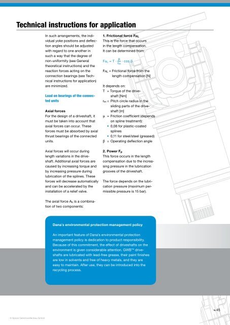
1. Frictional <strong>for</strong>ce F RL<br />
This is the <strong>for</strong>ce that occurs<br />
in the length compensation.<br />
It can be determined from:<br />
m<br />
F RL = T · · cos b<br />
r m<br />
F RL = Frictional <strong>for</strong>ce from the<br />
length compensation [N]<br />
It depends on:<br />
T = Torque of the driveshaft<br />
[Nm]<br />
r m = Pitch circle radius in the<br />
sliding parts of the driveshaft<br />
[m]<br />
m = Friction coefficient (depends<br />
on spline treatment):<br />
• 0,08 <strong>for</strong> plastic-coated<br />
splines<br />
• 0,11 <strong>for</strong> steel/steel (greased)<br />
b = Operating deflection angle<br />
Axial <strong>for</strong>ces will occur during<br />
length variations in the driveshaft.<br />
Additional axial <strong>for</strong>ces are<br />
caused by increasing torque and<br />
by increasing pressure during<br />
lubrication of the splines. These<br />
<strong>for</strong>ces will decrease automatically<br />
and can be accelerated by the<br />
installation of a relief valve.<br />
2. Power F p<br />
This <strong>for</strong>ce occurs in the length<br />
compensation due to the increasing<br />
pressure in the lubrication<br />
grooves of the driveshaft.<br />
The <strong>for</strong>ce depends on the lubrication<br />
pressure (maximum permissible<br />
pressure is 15 bar).<br />
The axial <strong>for</strong>ce A k is a combination<br />
of two components:<br />
Dana’s environmental protection management policy<br />
An important feature of Dana’s environmental protection<br />
management policy is dedication to product responsibility.<br />
Because of this commitment, the effect of driveshafts on the<br />
environment is given considerable attention. <strong>GWB</strong> TM driveshafts<br />
are lubricated with lead-free grease, their paint finishes<br />
are low in solvents and free of heavy metals, and they are<br />
easy to maintain. After use, they can be introduced into the<br />
recycling process.<br />
45<br />
© Spicer Gelenkwellenbau GmbH