Driveshafts for Industrial Applications - GWB
Driveshafts for Industrial Applications - GWB
Driveshafts for Industrial Applications - GWB

You also want an ePaper? Increase the reach of your titles
YUMPU automatically turns print PDFs into web optimized ePapers that Google loves.
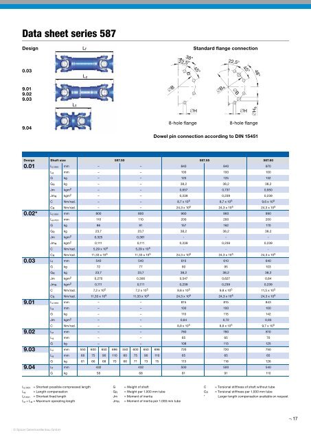
Data sheet series 587<br />
Design<br />
L f<br />
Standard flange connection<br />
38°<br />
22,5°<br />
22,5°<br />
0.03<br />
45°<br />
45°<br />
48°<br />
L z<br />
9.01<br />
9.02<br />
9.03<br />
∅B<br />
∅B s<br />
∅B<br />
L f<br />
∅H<br />
∅H<br />
∅Hs<br />
9.04<br />
8-hole flange<br />
8-hole flange<br />
Dowel pin connection according to DIN 15451<br />
Design Shaft size 587.50 587.55 587.60<br />
0.01<br />
0.02*<br />
L z min mm – – 840 840 870<br />
L a mm – – 100 100 100<br />
G kg – – 120 125 132<br />
G R kg – – 38,2 38,2 38,2<br />
Jm kgm 2 – – 0,657 0,737 0,950<br />
Jm R kgm 2 – – 0,239 0,239 0,239<br />
C Nm/rad. – – 8,7 x 10 5 8,7 x 10 5 9,6 x 10 5<br />
C R Nm/rad. – – 24,3 x 10 5 24,3 x 10 5 24,3 x 10 5<br />
L z min mm 800 800 960 960 990<br />
L a min mm 110 110 200 200 200<br />
G kg 86 91 157 162 170<br />
G R kg 23,7 23,7 38,2 38,2 38,2<br />
Jm kgm 2 0,325 0,361 - - -<br />
Jm R kgm 2 0,111 0,111 0,239 0,239 0,239<br />
0.03<br />
9.01<br />
9.02<br />
9.03<br />
9.04<br />
C Nm/rad. 5,29 x 10 5 5,29 x 10 5 - - -<br />
C R Nm/rad. 11,33 x 10 5 11,33 x 10 5 24,3 x 10 5 24,3 x 10 5 24,3 x 10 5<br />
L f mm 540 540 610 610 640<br />
G kg 72 77 90 95 103<br />
G R kg 23,7 23,7 38,2 38,2 38,2<br />
Jm kgm 2 0,270 0,306 0,547 0,627 0,84<br />
Jm R kgm 2 0,111 0,111 0,239 0,239 0,239<br />
C Nm/rad. 7,2 x 10 5 7,2 x 10 5 9,8 x 10 5 9,8 x 10 5 11,5 x 10 5<br />
C R Nm/rad. 11,33 x 10 5 11,33 x 10 5 24,3 x 10 5 24,3 x 10 5 24,3 x 10 5<br />
L z min mm – – 815 815 843<br />
L a mm – – 100 100 100<br />
G kg – – 110 115 142<br />
Jm kgm 2 – – 0,64 0,72 0,93<br />
C Nm/rad. – – 8,8 x 10 5 8,8 x 10 5 9,7 x 10 5<br />
L z mm – – 780 780 810<br />
L a mm – – 65 65 70<br />
G kg – – 108 113 125<br />
L z mm 550 600 650 696 550 600 650 696 720 720 750<br />
L a mm 60 75 90 110 60 75 90 110 65 65 65<br />
G kg 61 66 68 70 66 71 73 75 113 118 126<br />
L f mm 432 432 500 500 540<br />
G kg 58 68 81 91 110<br />
L z min = Shortest possible compressed length<br />
L a = Length compensation<br />
L f min = Shortest fi xed length<br />
L z + L a = Maximum operating length<br />
G<br />
G R<br />
Jm<br />
Jm R<br />
= Weight of shaft<br />
= Weight per 1.000 mm tube<br />
= Moment of inertia<br />
= Moment of inertia per 1.000 mm tube<br />
C = Torsional stiffness of shaft without tube<br />
C R = Torsional stiffness per 1.000 mm tube<br />
* Larger length compensation available on request<br />
17<br />
© Spicer Gelenkwellenbau GmbH