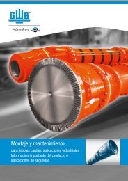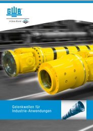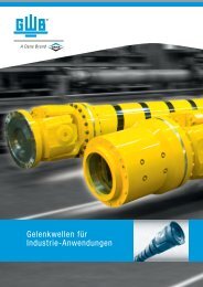
Driveshafts for Industrial Applications - GWB
Driveshafts for Industrial Applications - GWB
Driveshafts for Industrial Applications - GWB

You also want an ePaper? Increase the reach of your titles
YUMPU automatically turns print PDFs into web optimized ePapers that Google loves.
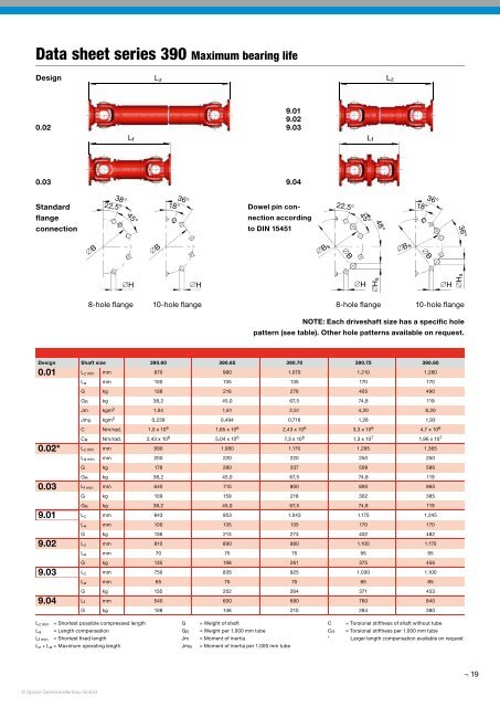
Data sheet series 390 Maximum bearing life<br />
Design<br />
L z<br />
L z<br />
0.02<br />
9.01<br />
9.02<br />
9.03<br />
L f<br />
L f<br />
0.03 9.04<br />
Standard<br />
flange<br />
connection<br />
38°<br />
22,5°<br />
45°<br />
18°<br />
36°<br />
Dowel pin connection<br />
according<br />
to DIN 15451<br />
22,5°<br />
45°<br />
48°<br />
18°<br />
36°<br />
36°<br />
∅B<br />
∅B<br />
∅B s<br />
∅B<br />
∅B s<br />
∅B<br />
∅H<br />
∅H<br />
∅H<br />
∅Hs<br />
∅H<br />
∅Hs<br />
8-hole flange<br />
10-hole flange<br />
8-hole flange<br />
10-hole flange<br />
NOTE: Each driveshaft size has a specific hole<br />
pattern (see table). Other hole patterns available on request.<br />
Design Shaft size 390.60 390.65 390.70 390.75 390.80<br />
0.01<br />
0.02*<br />
0.03<br />
9.01<br />
9.02<br />
9.03<br />
9.04<br />
L z min mm 870 980 1.070 1.210 1.280<br />
L a mm 100 135 135 170 170<br />
G kg 138 216 276 405 490<br />
G R kg 38,2 45,0 67,5 74,8 119<br />
Jm kgm 2 1,04 1,61 2,51 4,20 8,20<br />
Jm R kgm 2 0,239 0,494 0,716 1,28 1,93<br />
C Nm/rad. 1,0 x 10 6 1,65 x 10 6 2,43 x 10 6 3,3 x 10 6 4,7 x 10 6<br />
C R Nm/rad. 2,43 x 10 6 5,04 x 10 6 7,3 x 10 6 1,3 x 10 7 1,96 x 10 7<br />
L z min mm 990 1.080 1.170 1.295 1.365<br />
L a min mm 200 220 220 250 250<br />
G kg 178 280 337 508 586<br />
G R kg 38,2 45,0 67,5 74,8 119<br />
L f min mm 640 710 800 890 960<br />
G kg 109 159 218 302 385<br />
G R kg 38,2 45,0 67,5 74,8 119<br />
L z mm 843 953 1.043 1.175 1.245<br />
L a mm 100 135 135 170 170<br />
G kg 136 213 273 402 482<br />
L z mm 810 890 980 1.100 1.170<br />
L a mm 70 75 75 95 95<br />
G kg 135 198 261 375 456<br />
L z mm 750 835 925 1.030 1.100<br />
L a mm 65 75 75 85 85<br />
G kg 135 202 264 371 453<br />
L f mm 540 600 680 760 840<br />
G kg 108 146 210 284 380<br />
L z min = Shortest possible compressed length<br />
L a = Length compensation<br />
L f min = Shortest fi xed length<br />
L z + L a = Maximum operating length<br />
G<br />
G R<br />
Jm<br />
Jm R<br />
= Weight of shaft<br />
= Weight per 1.000 mm tube<br />
= Moment of inertia<br />
= Moment of inertia per 1.000 mm tube<br />
C = Torsional stiffness of shaft without tube<br />
C R = Torsional stiffness per 1.000 mm tube<br />
* Larger length compensation available on request<br />
19<br />
© Spicer Gelenkwellenbau GmbH