Driveshafts for Industrial Applications - GWB
Driveshafts for Industrial Applications - GWB
Driveshafts for Industrial Applications - GWB

You also want an ePaper? Increase the reach of your titles
YUMPU automatically turns print PDFs into web optimized ePapers that Google loves.
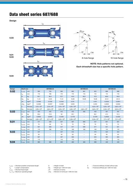
Data sheet series 687/688<br />
Design<br />
L f<br />
22,5°<br />
36°<br />
0.03<br />
45°<br />
L z<br />
∅B<br />
∅B<br />
9.01<br />
9.03<br />
∅H<br />
8-hole flange<br />
∅H<br />
10-hole flange<br />
L f<br />
NOTE: Hole patterns not optional.<br />
Each driveshaft size has a specific hole pattern.<br />
9.04<br />
Design Shaft size 687/688.45 687/688.55 687/688.65<br />
0.02<br />
0.03<br />
9.01<br />
9.03<br />
9.04<br />
L z min mm 595 703 585 662 681 622 686 686<br />
L a mm 110 180 110 110 110 110 110 110<br />
G kg 35,7 38,4 37,7 44,0 49,2 47,0 60,6 64,6<br />
G R kg 11,44 12,95 11,44 16,86 16,86 16,86 20,12 20,12<br />
Jm kgm 2 0,1002 0,1242 0,1342 0,131 – 0,151 0,2224 0,2614<br />
Jm R kgm 2 0,0385 0,0357 0,0385 0,055 – 0,055 0,0932 0,0932<br />
C Nm/rad. 3,10 x 10 5 2,18 x 10 5 3,10 x 10 5 4,05 x 10 5 – 4,05 x 10 5 5,63 x 10 5 5,63 x 10 5<br />
C R Nm/rad. 3,93 x 10 5 3,65 x 10 5 3,93 x 10 5 5,60 x 10 5 5,60 x 10 5 5,60 x 10 5 9,50 x 10 5 9,50 x 10 5<br />
L f min mm 425 425 415 475 495 435 491 491<br />
G kg 28,0 27,8 30 33,1 – 36,1 47,3 51,3<br />
Jm kgm 2 0,0954 0,0976 0,1294 0,1176 – 0,1376 0,2032 0,2422<br />
C Nm/rad. 4,82 x 10 5 3,71 x 10 5 4,82 x 10 5 5,39 x 10 5 – 5,39 x 10 5 7,17 x 10 5 7,17 x 10 5<br />
L z min mm 517 538 507 587 606 547 601 601<br />
L a min mm 70 60 70 70 70 70 70 70<br />
L z max mm 557 658 547 617 636 577 641 641<br />
L a max mm 110 180 110 100 100 100 110 110<br />
L z min mm 447 – 437 513 – 473 524 524<br />
L a min mm 50 – 50 50 – 50 50 50<br />
L z max mm 507 – 497 563 – 523 584 584<br />
L a max mm 110 – 110 110 – 110 110 110<br />
L f min mm 380 380 360 460 460 380 440 440<br />
L z min = Shortest possible compressed length<br />
L a = Length compensation<br />
L f min = Shortest fi xed length<br />
L z + L a = Maximum operating length<br />
G<br />
G R<br />
Jm<br />
Jm R<br />
= Weight of shaft<br />
= Weight per 1.000 mm tube<br />
= Moment of inertia<br />
= Moment of inertia per 1.000 mm tube<br />
C<br />
C R<br />
= Torsional stiffness of shaft without tube<br />
= Torsional stiffness per 1.000 mm tube<br />
15<br />
© Spicer Gelenkwellenbau GmbH