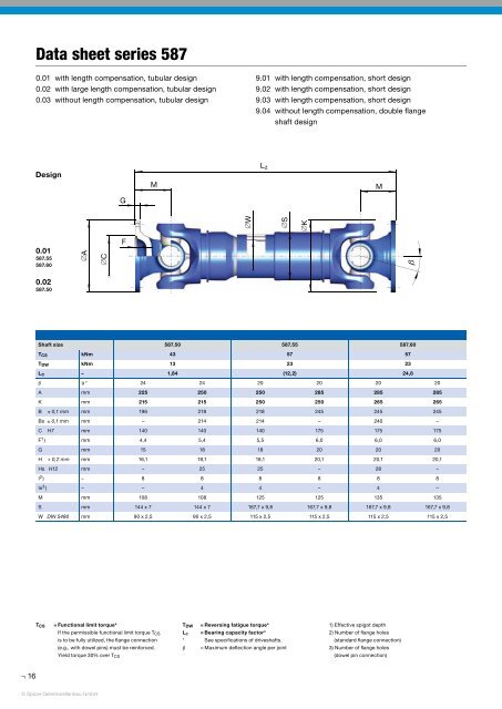
Data sheet series 587 0.01 with length compensation, tubular design 0.02 with large length compensation, tubular design 0.03 without length compensation, tubular design 9.01 with length compensation, short design 9.02 with length compensation, short design 9.03 with length compensation, short design 9.04 without length compensation, double flange shaft design Design M L z M G ∅W ∅S ∅K 0.01 587.55 587.60 ∅A ∅C F b 0.02 587.50 Shaft size T CS kNm T DW kNm Lc – b
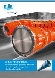
Data sheet series 587 Design L f Standard flange connection 38° 22,5° 22,5° 0.03 45° 45° 48° L z 9.01 9.02 9.03 ∅B ∅B s ∅B L f ∅H ∅H ∅Hs 9.04 8-hole flange 8-hole flange Dowel pin connection according to DIN 15451 Design Shaft size 587.50 587.55 587.60 0.01 0.02* L z min mm – – 840 840 870 L a mm – – 100 100 100 G kg – – 120 125 132 G R kg – – 38,2 38,2 38,2 Jm kgm 2 – – 0,657 0,737 0,950 Jm R kgm 2 – – 0,239 0,239 0,239 C Nm/rad. – – 8,7 x 10 5 8,7 x 10 5 9,6 x 10 5 C R Nm/rad. – – 24,3 x 10 5 24,3 x 10 5 24,3 x 10 5 L z min mm 800 800 960 960 990 L a min mm 110 110 200 200 200 G kg 86 91 157 162 170 G R kg 23,7 23,7 38,2 38,2 38,2 Jm kgm 2 0,325 0,361 - - - Jm R kgm 2 0,111 0,111 0,239 0,239 0,239 0.03 9.01 9.02 9.03 9.04 C Nm/rad. 5,29 x 10 5 5,29 x 10 5 - - - C R Nm/rad. 11,33 x 10 5 11,33 x 10 5 24,3 x 10 5 24,3 x 10 5 24,3 x 10 5 L f mm 540 540 610 610 640 G kg 72 77 90 95 103 G R kg 23,7 23,7 38,2 38,2 38,2 Jm kgm 2 0,270 0,306 0,547 0,627 0,84 Jm R kgm 2 0,111 0,111 0,239 0,239 0,239 C Nm/rad. 7,2 x 10 5 7,2 x 10 5 9,8 x 10 5 9,8 x 10 5 11,5 x 10 5 C R Nm/rad. 11,33 x 10 5 11,33 x 10 5 24,3 x 10 5 24,3 x 10 5 24,3 x 10 5 L z min mm – – 815 815 843 L a mm – – 100 100 100 G kg – – 110 115 142 Jm kgm 2 – – 0,64 0,72 0,93 C Nm/rad. – – 8,8 x 10 5 8,8 x 10 5 9,7 x 10 5 L z mm – – 780 780 810 L a mm – – 65 65 70 G kg – – 108 113 125 L z mm 550 600 650 696 550 600 650 696 720 720 750 L a mm 60 75 90 110 60 75 90 110 65 65 65 G kg 61 66 68 70 66 71 73 75 113 118 126 L f mm 432 432 500 500 540 G kg 58 68 81 91 110 L z min = Shortest possible compressed length L a = Length compensation L f min = Shortest fi xed length L z + L a = Maximum operating length G G R Jm Jm R = Weight of shaft = Weight per 1.000 mm tube = Moment of inertia = Moment of inertia per 1.000 mm tube C = Torsional stiffness of shaft without tube C R = Torsional stiffness per 1.000 mm tube * Larger length compensation available on request 17 © Spicer Gelenkwellenbau GmbH