Driveshafts for Industrial Applications - GWB
Driveshafts for Industrial Applications - GWB
Driveshafts for Industrial Applications - GWB

You also want an ePaper? Increase the reach of your titles
YUMPU automatically turns print PDFs into web optimized ePapers that Google loves.
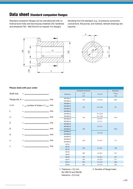
Data sheet Standard companion flanges<br />
Standard companion flanges can be manufactured with cylindrical<br />
bore holes and face keyway (material C45; hardened<br />
and tempered 750 – 900 N/mm 2 ) on request. For designs<br />
deviating from the standard, e.g., oil pressure connection,<br />
conical bore, flat journal, and material, relevant drawings are<br />
required.<br />
u<br />
∅A<br />
∅Z<br />
L 1<br />
∅D<br />
∅d<br />
v<br />
∅H<br />
L<br />
Please state with your order:<br />
Shaft size =<br />
Flange dia. A =<br />
mm<br />
I x H = number of holes x ∅ mm<br />
L = mm<br />
L 1 = mm<br />
Z = mm<br />
D = mm<br />
d = mm<br />
u = mm<br />
v = mm<br />
Driveshaft connection<br />
Dimension<br />
Shaft size<br />
∅ A<br />
I 2 ) x H 1 )<br />
∅ D max<br />
mm<br />
mm<br />
687/688.15<br />
100 6 x 8,25 69,5<br />
687/688.20<br />
687/688.15<br />
687/688.20<br />
120 8 x 10,25 84<br />
687/688.25<br />
687/688.30<br />
687/688.25<br />
8 x 12,25<br />
687/688.30<br />
150<br />
8 x 12,25<br />
110,3<br />
687/688.35<br />
687/688.40<br />
687/688.35<br />
687/688.40<br />
8 x 12,1<br />
8 x 12,1<br />
8 x 14,1<br />
687/688.45<br />
180 132,5<br />
687/688.55<br />
10 x 16,1<br />
687/688.65<br />
687/688.45<br />
687/688.55<br />
225 8 x 16,1 171<br />
687/688.65<br />
587.50<br />
587.50<br />
250 8 x 18,1 189<br />
587.55<br />
587.60<br />
285 8 x 20,1 213<br />
390.60<br />
390.65<br />
315 8 x 22,1 247<br />
390.70<br />
350 10 x 22,1 277<br />
390.75<br />
390 10 x 24,1 308<br />
390.80<br />
435 10 x 27,1 342<br />
1. Tolerance + 0,2 mm<br />
(<strong>for</strong> 390.75 and 390.80,<br />
tolerance + 0,5 mm)<br />
2. Number of flange holes<br />
33<br />
© Spicer Gelenkwellenbau GmbH