DUS804C-NA DUS804C-SM-NA - Philips Lighting Controls
DUS804C-NA DUS804C-SM-NA - Philips Lighting Controls
DUS804C-NA DUS804C-SM-NA - Philips Lighting Controls

Create successful ePaper yourself
Turn your PDF publications into a flip-book with our unique Google optimized e-Paper software.
…………………………………………………....…………………………………………………………<br />
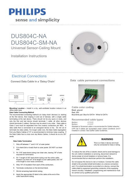
<strong>DUS804C</strong>-<strong>NA</strong><br />
<strong>DUS804C</strong>-<strong>SM</strong>-<strong>NA</strong><br />
Universal Sensor-Ceiling Mount<br />
Installation Instructions<br />
…………………………………………………....…………………………………………………………<br />
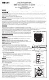
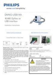
Electrical Connections<br />
Connect Data Cable in a ‘Daisy Chain’<br />
Data cable permanent connections<br />
Mounting Location – Install in a dry, well-ventilated location indoors in an<br />
office-clean area.<br />
Data Cable Connecting Method<br />
The recommended connecting method is to ‘daisy chain’ devices (i.e. starting<br />
at the first device, then looping in and out of devices, with a single cable<br />
terminating at the last device. There should not be any spurs or stubs, and<br />
only the first and last device should terminate 1 cable, all other devices<br />
should terminate 2 cables). Devices may be wired in any order. Data cable is<br />
Class 2 and must be separated from line (mains) conductors per NEC. A<br />
data cable that is connected to an energized device is live. Do not cut or<br />
terminate live data cables. For longer cable runs, the Data Cable segregation<br />
from any Mains Cables of 12” is recommended to minimize noise coupling. If<br />
the Data Cable has to cross over any Mains Cables, it should do so at a 90°<br />
angle.<br />
Data Cable Termination<br />
1. Strip off between 1” and 2-1/4” of outer jacket.<br />
2. Cut shield (foil or braid) flush to outer jacket. DO NOT cut drain<br />
wire.<br />
3. Fit 1/16” heat-shrink tubing over drain wire, leaving 1/8” of wire<br />
exposed for termination.<br />
4. Fit 1” length of 3/8” heat-shrink tubing over the entire cable.<br />
Position it so that 3/4” of its length is over cable jacket, and 1/4”<br />
of its length is over loose connectors.<br />
5. Strip 1/8” of insulation from each of the conductors.<br />
6. Terminate conductors on the terminal block.<br />
7. Shrink remaining heat-shrink tubing.<br />
8. Apply the appropriate ID label to the cable at the end of the<br />
outer heat-shrink tubing.<br />
Cable color coding<br />
Black: ground<br />
Red: 24V<br />
Blue/white pair: Blue for DATA+ White for DATA-<br />
Recommended cable types<br />
Belden: #1502R<br />
Belden: #1502P<br />
Shielded or Screened cable is recommended for DyNet networks.<br />
UTP Cat 5 cables are acceptable under certain conditions and if<br />
installed in conduit. See DyNet Cable Guidelines.<br />
WARNING<br />
This is a Class 2 device and must<br />
only be connected to Class 2 wiring.<br />
To reduce the risk of fire or electric shock and to avoid damage to<br />
the unit, before installation or servicing, disconnect network &<br />
device power at circuit breakers or remove fuses. It is<br />
recommended that an electrician perform this installation.<br />
Do not expose this device to rain or moisture. Connect the cable<br />
shield to the provided shield termination on a device connection<br />
port. If no shield termination is provided on a device, connect the<br />
cable shield to equipment grounding conductor of the supplying<br />
branch circuit(s). Installation, programming and maintenance must<br />
be carried out by qualified personnel.
…………………………………………………....…………………………………………………………<br />
Installation Steps<br />
1. Select an appropriate indoor mounting location. Select a location where persons are more likely to walk across the<br />
detection “fingers” rather than into them (see Lens Pattern in Data Sheet). Optimum height for the sensor is 10 feet.<br />
2. Position the sensor so it is at least 7 feet away from electrical lighting such as neon and fluorescent lights and not exposed<br />
to direct sunlight and heating / cooling sources.<br />
3. This unit is designed for installation in a 2.5 inch diameter hole where the ceiling void is at least 2 inches deep.<br />
4. Wire the sensor following the recommendations ; See data cable permanent connections<br />
5. Insert the sensor into the ceiling and secure using spring clips provided.<br />
6. Rotate sensor housing and/or click-up PIR masking bezels for optimum performance to match sensing pattern with<br />
occupancy requirements.<br />
……………………………………………....…………………………………………………………<br />
Mounting Dimensions<br />
This device complies with Part 15 of the<br />
FCC Rules. Operation is subject to the<br />
following two conditions:<br />
…………………………………………………....…………………………………………………………<br />
(1) This device may not cause harmful<br />
interference<br />
and<br />
(2) This device must accept any<br />
interference received, including<br />
interference that may cause<br />
undesired operation.<br />
This Class A digital apparatus complies<br />
with Canadian ICES-003<br />
…………………………………………………....…………………………………………………………<br />
Product Specifications<br />
<strong>DUS804C</strong>-<strong>NA</strong><br />
<strong>DUS804C</strong>-<strong>SM</strong>- <strong>NA</strong><br />
Standard Motion Sensitivity<br />
Slight Motion Sensitivity<br />
Maximum detection range: 16’ Maximum detection range: 6.5’<br />
Detection Area: 24’ X18’ rectangular (at a height of 8’) Detection Area: 6.5’ circular (at a height of 8’)<br />
Detection speed: 13.3 ft/s<br />
Detection speed: 1.65 ft/s<br />
Detection object: 2.2’ x 0.8’ Detection object: 7.9”x 7.9”<br />
Detection zones: 64 Detection zones: 104<br />
LED activation indicator<br />
LED activation indicator<br />
Sensor: Quad element PIR<br />
Sensor: Quad element PIR<br />
DyNet DC Load max. 10mA@24VDC Terminals<br />
Control IO RS485 DyNet port<br />
Standard:<br />
User <strong>Controls</strong><br />
5 way removable screw terminal<br />
Walk test/IR received LED indicator, service pushbutton<br />
1 x 14AWG or 2 x 18AWG max conductor size<br />
PE Cell Dynamic range<br />
Configuration<br />
5 - 500 lux (incident on sensor) All functions remotely programmable<br />
5 - 5000 lux (illumination of non-reflective surface in sensor’s field of Compliance RoHS ,FCC, ICES Compliant (see statements)<br />
view)<br />
Value subject to the reflectance properties of the surface<br />
Operating Environment<br />
Automatic “Daylight Harvesting” mode<br />
32º to 122ºF (0º to 50ºC) ambient temp<br />
Can be used for light measurement<br />
0% to 90% RH non condensing<br />
Infrared Remote Control <strong>DUS804C</strong> Receiver Installation Instructions draft. 22 nd July 2010. Specifications Construction subject to change without notice. All rights reserved.<br />
Dynalite, DyNet and associated logos are the registered trademarks of <strong>Philips</strong> Dynalite. Not to be reproduced without permission.<br />
Range up to 19’, angle dependent<br />
ABS plastic enclosure<br />
Manufactured by WMGD Pty Ltd (ABN 33 097 246 921) Unit 6, 691 Gardeners Road, Mascot, NSW 2020, Australia<br />
Can be used with DTK500 series infrared remotes Web: or lightolier.com other learning E-Mail: IR controls.support@philips.com. Dimensions<br />
T<br />
Remote controls 4.8” diameter x D 1.0”<br />
el: 1-800-526-2731<br />
Weight<br />
Packed weight 0.3 lb<br />
………………………………………………....…………………………………………………………<br />
…………………………………………………....…………………………………………………………<br />
…………………………………………………....………………………………………………..<br />
<strong>DUS804C</strong>-<strong>NA</strong> & <strong>DUS804C</strong>-<strong>SM</strong>-<strong>NA</strong> Rev B Oct 9 2010 Installation Instructions. Specifications subject to change without notice. All rights reserved.<br />
Dynalite, DyNet and associated logos are the registered trademarks of <strong>Philips</strong> Dynalite. Not to be reproduced without permission.<br />
Manufactured by WMGD Pty Ltd (ABN 33 097 246 921) Unit 6, 691 Gardeners Road, Mascot, NSW 2020, Australia<br />
Web: lightolier.com E-Mail: controls.support@philips.com. Tel: 1-800-526-2731