Crosscut Saw Manual Crosscut Saw Manual - USDA Forest Service
Crosscut Saw Manual Crosscut Saw Manual - USDA Forest Service
Crosscut Saw Manual Crosscut Saw Manual - USDA Forest Service

Create successful ePaper yourself
Turn your PDF publications into a flip-book with our unique Google optimized e-Paper software.
United States<br />
Department of<br />
Agriculture<br />
<strong>Forest</strong> <strong>Service</strong><br />
Technology &<br />
Development<br />
Program<br />
7100 Engineering<br />
2300 Recreation<br />
June 1977<br />
Rev. December 2003<br />
7771-2508-MTDC<br />
United States<br />
Department of<br />
Agriculture<br />
<strong>Forest</strong> <strong>Service</strong><br />
Technology &<br />
Development<br />
Program<br />
7100 Engineering<br />
2300 Recreation<br />
June 1977<br />
Rev. December 2003<br />
7771-2508-MTDC<br />
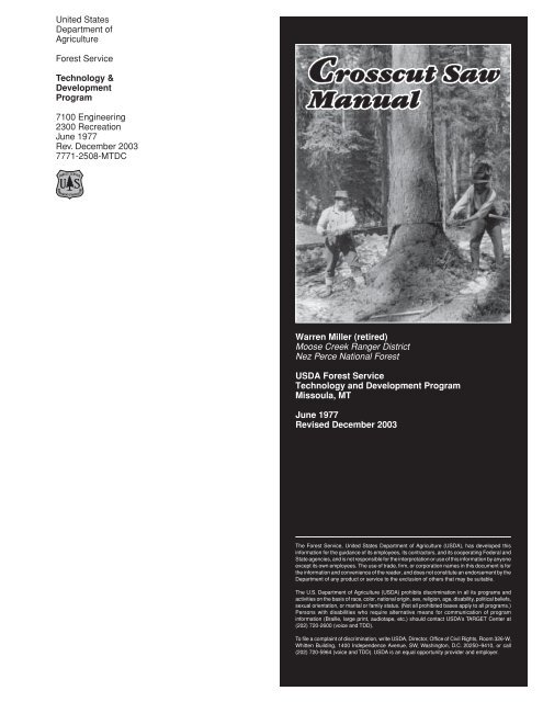
<strong>Crosscut</strong> <strong>Saw</strong><br />
<strong>Manual</strong><br />
Warren Miller (retired)<br />
Moose Creek Ranger District<br />
Nez Perce National <strong>Forest</strong><br />
<strong>USDA</strong> <strong>Forest</strong> <strong>Service</strong><br />
Technology and Development Program<br />
Missoula, MT<br />
June 1977<br />
Revised December 2003<br />
The <strong>Forest</strong> <strong>Service</strong>, United States Department of Agriculture (<strong>USDA</strong>), has developed this<br />
information for the guidance of its employees, its contractors, and its cooperating Federal and<br />
State agencies, and is not responsible for the interpretation or use of this information by anyone<br />
except its own employees. The use of trade, firm, or corporation names in this document is for<br />
the information and convenience of the reader, and does not constitute an endorsement by the<br />
Department of any product or service to the exclusion of others that may be suitable.<br />
The U.S. Department of Agriculture (<strong>USDA</strong>) prohibits discrimination in all its programs and<br />
activities on the basis of race, color, national origin, sex, religion, age, disability, political beliefs,<br />
sexual orientation, or marital or family status. (Not all prohibited bases apply to all programs.)<br />
Persons with disabilities who require alternative means for communication of program<br />
information (Braille, large print, audiotape, etc.) should contact <strong>USDA</strong>’s TARGET Center at<br />
(202) 720-2600 (voice and TDD).<br />
To file a complaint of discrimination, write <strong>USDA</strong>, Director, Office of Civil Rights, Room 326-W,<br />
Whitten Building, 1400 Independence Avenue, SW, Washington, D.C. 20250–9410, or call<br />
(202) 720-5964 (voice and TDD). <strong>USDA</strong> is an equal opportunity provider and employer.<br />
i
Contents<br />
Introduction ___________________________________ 1<br />
The <strong>Crosscut</strong> <strong>Saw</strong> ______________________________ 2<br />
How a <strong>Saw</strong> Cuts ________________________________ 5<br />
<strong>Saw</strong> Vise _______________________________________ 6<br />
Filing the <strong>Saw</strong> _________________________________ 8<br />
Cleaning _________________________________________________ 8<br />
Hammering or Straightening __________________________________ 8<br />
Jointing __________________________________________________ 9<br />
Short Jointer ___________________________________________________________ 10<br />
Long Jointer ____________________________________________________________ 10<br />
Raker Fitting _____________________________________________ 12<br />
Fitting Straight Rakers ____________________________________________________ 13<br />
Fitting Swaged Rakers ____________________________________________________ 14<br />
Repairing Bent Rakers and Cutter Teeth ______________________________________ 16<br />
Broken Raker Tip ________________________________________________________ 16<br />
Pointing Up Cutter Teeth ____________________________________ 16<br />
Setting __________________________________________________ 17<br />
Testing a <strong>Saw</strong> _________________________________ 21<br />
Choosing and Using a <strong>Saw</strong> ___________________ 22<br />
Handle Positions _____________________________ 24<br />
Storing <strong>Saw</strong>s __________________________________ 25<br />
Glossary ______________________________________ 26<br />
ii
Acknowledgments<br />
This manual would never have been possible without the willing and patient<br />
teaching of Martin Winters, accomplished filer from the days when the crosscut<br />
saw reigned.<br />
Also, special thanks to Clem Pope, friend and coworker with a mutual interest<br />
in crosscuts, and William Harlow, professor emeritus of wood technology, State<br />
University of New York, for their many helpful comments and contributions to<br />
the text.<br />
There are persons too numerous to name here who contributed knowingly and<br />
unknowingly to this manual: sawyers, filers, and others, all of whom have something<br />
in common—knowledge about the crosscut saw and a willingness to share<br />
that knowledge. To these important individuals I give my appreciation.<br />
Finally, my thanks to staff members of the Technology and Development Center<br />
at Missoula for their suggestions during the preparation of this manual.<br />
—Cover photo: Northern Region <strong>Forest</strong> <strong>Service</strong> file photo by K.D. Swan, 1924,<br />
on the Flathead National <strong>Forest</strong> near Radnor, MT.<br />
iii
Introduction<br />
Many readers undoubtedly have run crosscut saws in<br />
the past, and a lot of you know the difference between<br />
a good running saw and a poorly filed one. A poorly filed<br />
saw deserves the name I have often heard attributed to it…<br />
“misery whip.” A well-filed saw, however, is efficient and can<br />
be satisfying to use. Only in recent years was a chain saw<br />
developed that could beat a topnotch bucker in a contest. There<br />
is a record of a 32-inch Douglas-fir log cut in 1 minute 26 2 ⁄ 5<br />
seconds by one bucker.<br />
<strong>Saw</strong> filers of any quality are becoming very difficult—if not<br />
impossible—to find. This manual was written so those of you<br />
who use crosscut saws can maintain them yourselves and<br />
overcome some of the misery of that ol’ whip.<br />
The manual provides a basic description of how and why a<br />
crosscut saw works, tips on building a saw vise, and some<br />
experience-tested methods as a guide for achieving a wellrunning<br />
saw.<br />
Only saws having raker teeth are discussed, because they<br />
are by far the most common saws found today. This includes<br />
lance, perforated-lance, and champion tooth patterns.<br />
1
The <strong>Crosscut</strong> <strong>Saw</strong><br />
The two-person crosscut saw was evidently known by the<br />
Romans though little used by them. It wasn’t until the<br />
middle of the 15th century that the crosscut saw came<br />
into fairly common use in Europe. Records exist of the crosscut<br />
being used for cutting logs in the United States between 1635<br />
and 1681. About 1880, Pennsylvania lumbermen began felling<br />
trees with the crosscut. Before that time, all trees had been<br />
ax-felled and crosscut into lengths.<br />
Until the 15th century, the two-person crosscut saw used a<br />
plain tooth pattern. The M tooth pattern seems to have been<br />
developed and used in south Germany in the 1400s. Even<br />
as late as 1900 most of the European crosscuts still used the<br />
plain tooth pattern with a few exceptions of M tooth being used.<br />
Not until fairly recently was the saw with a raker or “drag”<br />
developed.<br />
In the case of plain, M, and Great American tooth patterns,<br />
each tooth both cuts the wood and clears out the shavings.<br />
However, in the case of the champion, lance, and perforatedlance<br />
tooth, cutter teeth cut the wood fibers and the rakers<br />
remove the scored wood from the cut.<br />
By the time crosscut use was at its peak, a large number of<br />
tooth patterns had been developed, each presumably suited<br />
to a particular set of conditions.<br />
<strong>Saw</strong>s can be divided into two types: two person and one<br />
person. Generally speaking, a one-person saw is shorter, but<br />
its defining characteristic is that it is asymmetric. Both oneand<br />
two-person crosscut saws can be used by either one or<br />
two persons.<br />
At one time, one-person crosscut saws were made in lengths<br />
from 3 to 6 feet. Two-person saws were made in lengths from<br />
4 to 12 feet for the Pacific Northwest, and up to 16 feet for the<br />
California redwoods. If a longer saw was needed, two shorter<br />
saws were sometimes brazed together.<br />
There are two basic saw patterns for the two-person saw: the<br />
felling pattern for felling trees and the bucking pattern for<br />
cutting up trees once they are on the ground. Each has<br />
characteristics suited to its use.<br />
Plain tooth<br />
Tooth patterns<br />
Champion tooth<br />
M tooth<br />
Lance tooth<br />
Great American tooth<br />
Perforated lance tooth<br />
2
The <strong>Crosscut</strong> <strong>Saw</strong><br />
One-person saw<br />
Two-person saw<br />
The felling saw has a concave back and is relatively light and<br />
flexible. It is light so less effort is needed to move it back and<br />
forth when felling a tree. It is flexible to conform to the arc a<br />
sawyer’s arms take when sawing, and it is narrow tooth-to-back,<br />
enabling the sawyer to place a wedge in the cut behind the<br />
saw sooner than with a wide saw.<br />
The bucking saw has a straight back. It is much thicker toothto-back<br />
than the felling saw, so it is heavier and stiffer. A bucking<br />
saw traditionally is used by one person, so it is a fairly stiff saw<br />
designed to help prevent buckling on the push stroke. The more<br />
weight put on a saw, the faster it will cut, so the weight of a<br />
bucking saw is an asset.<br />
The points of the teeth of nearly all crosscut saws lie on the<br />
arc of a circle. This result is a saw that cuts easier and faster<br />
than a straight saw. A circular contour is much simpler to<br />
maintain than a contour of any other shape (except straight).<br />
There are three ways that the sides of a saw are finished (ground)<br />
when manufactured. Each finish affects the thickness of the<br />
saw in a particular way. These finishes are: flat, straight<br />
taper, and crescent taper.<br />
A flat-ground saw has the same thickness everywhere. A taperground<br />
saw is thicker at the teeth than at the top edge of the<br />
Felling saw<br />
Bucking saw<br />
3
The <strong>Crosscut</strong> <strong>Saw</strong><br />
saw. It is not as likely to bind in a cut, especially if the kerf is<br />
closing behind the saw as happens if the wood being cut is<br />
under compression. Another advantage is that a taperground<br />
saw requires less set than a flat-ground saw.<br />
The difference between a straight taper and a crescent taper<br />
is in the lines of equithickness for the two saws: straight lines<br />
as opposed to lines concentric to the circle of the saw. This<br />
means that the teeth of a saw ground with a crescent taper<br />
are the same thickness, while the teeth of a saw ground with<br />
a straight taper are thicker toward the center of the saw.<br />
The uniform tooth thickness of a saw ground with a crescent<br />
taper is an obvious advantage over the varying tooth thickness<br />
of a saw ground with a straight taper. Trademarks indicating<br />
saws are ground with a crescent taper are Crescent Ground,<br />
Precision Ground, Segment Ground, and Arc Ground.<br />
Top edge (exaggerated for clarity)<br />
Each line represents uniform thickness, tapering<br />
from thick at the teeth to thin at the top.<br />
End<br />
view<br />
Crescent taper ground<br />
Top edge<br />
End<br />
view<br />
Straight taper ground<br />
Taper-ground cut—Not as likely to bind<br />
Flat-ground cut—Tends to bind when cutting under compression<br />
4
How a <strong>Saw</strong> Cuts<br />
The cutting teeth of a crosscut saw sever the fibers on<br />
each side of the kerf. The raker teeth, cutting like a plane<br />
bit, peel the cut fibers and collect them in the sawdust<br />
gullets between the cutting teeth and the raker teeth and carry<br />
them out of the cut. A properly sharpened crosscut saw cuts<br />
deep and makes thick shavings. On large timber, where the<br />
amount of shavings accumulated per stroke is considerable,<br />
a large gullet is necessary to carry out the shavings to prevent<br />
the saw from binding.<br />
How a saw cuts<br />
5
<strong>Saw</strong> Vise<br />
When possible, a saw should be filed in a saw vise. A vise<br />
helps a filer do a good job.<br />
The essential qualities of a vise are a flat surface against which<br />
a saw can be held rigidly in such a position that the teeth can<br />
be conveniently worked on.<br />
A carpenter’s handsaw vise can be used if only a few saws are<br />
sharpened, but a vise especially built for crosscut saws is best.<br />
One way of making a vise is to use a straight, clear board, 3 by<br />
8 inches or 3 by 10 inches, which has one edge shaped to fit the<br />
curve of a saw (1). If you can’t obtain these sizes, two 2- by 8-<br />
inch or 2- by 10-inch boards can be glued and bolted (or screwed)<br />
together. Ensure that the surface remains flat. You can use a<br />
single 2- by 8-inch or 2- by 10-inch board, but I don’t recommend<br />
this because of the lack of rigidity. The saw is held against<br />
the board with hardwood strips about 1 1 ⁄ 2 inches wide, 1 ⁄ 4 to 3 ⁄ 8<br />
inch thick, and 6 to 8 inches long. Fasten the strips to the<br />
board at positions coinciding with every other raker tooth.<br />
Fasten each strip with bolts or screws. The ends of the strips<br />
should not project beyond the curved edge of the board. On<br />
each bolt or screw, place a washer as thick as the saw blade<br />
between the strip and board so the strips tighten snugly against<br />
the saw blade and hold the saw firmly against the board.<br />
The saw should fit the vise so that the teeth project above the<br />
curved edge of the board far enough so they can be filed<br />
without the file touching the vise.<br />
Another method of making a vise is to use two shaped 2 by<br />
8s or 2 by 10s and clamp the saw between them (2). Several<br />
bolts and wingnuts through the bottom part of the vise can be<br />
used to clamp the saw between the two boards.<br />
Mount the vise so it will rotate around its long axis. This allows<br />
the filer to change the saw from the vertical where most of the<br />
operations are done, to an oblique angle where the cutter teeth<br />
are filed or “pointed up.”<br />
To mount the vise in this way, insert a piece of threaded rod<br />
(about 5 ⁄ 8 inch) into each end of the vise and glue or pin it<br />
securely, leaving 4 to 6 inches sticking out. Position the vise<br />
so the threaded rods are between the uprights of the bench<br />
brackets that hold the vise a couple of inches above elbow<br />
height—or a comfortable height for the filer. Wingnuts tightened<br />
on the rod ends hold the vise securely.<br />
The vise also can be mounted directly to a workbench with<br />
hinges (3) so it can be tilted back for the pointing-up operation.<br />
Several stops behind the vise hold it firmly at the desired angle.<br />
6
<strong>Saw</strong> Vise<br />
<strong>Saw</strong> vise styles<br />
3-by-8 or 3-by-10 board with one<br />
edge shaped to the saw’s curve<br />
1<br />
Wingnuts<br />
Threaded rods<br />
Washer<br />
spacers<br />
Hardwood strips<br />
Carriage bolt (or<br />
two screws)<br />
Bench brackets (two)<br />
2<br />
Wingnuts<br />
Threaded rods<br />
Carriage bolts<br />
Two 3-by-8 or 3-by-10 boards shaped<br />
to the saw’s curve on one edge<br />
3<br />
Wood blocks<br />
Hinges<br />
7
Filing the <strong>Saw</strong><br />
Opinions vary among saw filers on the order of steps followed<br />
in filing a saw. Guidelines offered by saw companies<br />
differ significantly. After examining the reasons<br />
for the different orders, I prefer the following order:<br />
• Setting<br />
—8-ounce set hammer (or tinner’s riveting hammer).<br />
—Setting stake or set tool, or anvil and spider.<br />
—<strong>Saw</strong> vise.<br />
• Cleaning—removing rust or pitch.<br />
• Hammering—straightening a saw if it has bumps, kinks, or<br />
twists.<br />
• Jointing—the means by which the tips of all the cutter teeth<br />
on the saw are made to conform to the circle of the saw.<br />
• Raker fitting—includes shaping the raker gullet and swaging<br />
and sharpening the raker.<br />
• Pointing up cutter teeth—sharpening the teeth by filing.<br />
• Setting—bending the tips of the cutter teeth away from the<br />
plane of the saw, causing the kerf to be wider than the saw.<br />
Cleaning<br />
Often a filer must clean a rusty or pitchy saw. One good method<br />
is to lay the saw on a flat surface and clean it with an ax stone<br />
or a pumice grill stone. Liberally douse the saw with a citrusbased<br />
solvent to dissolve the pitch and keep the stone from<br />
plugging up with debris. Small kinks show up as bright areas<br />
when they are high spots and dark areas when they are low<br />
spots. Use only enough pressure on the cutter teeth to clean<br />
them. If metal is taken off the tips, both set and tooth length<br />
will be affected.<br />
Tools necessary for:<br />
• Hammering<br />
—Two steel straightedges about 10 to 14 inches long.<br />
—3- to 4-pound cross-pein saw hammer (some manufacturers<br />
call them cross-face hammers).<br />
—Fairly flat anvil.<br />
• Jointing<br />
—Jointer (short or long).<br />
—7- or 8-inch special crosscut file (mill bastard blunt file).<br />
—<strong>Saw</strong> vise.<br />
• Raker fitting<br />
—7- or 8-inch slim-taper (triangular) file.<br />
—Pin gauge, raker gauge, or 8- to 16-ounce tinner’s<br />
riveting hammer for swaging.<br />
—6-inch, slim-taper file with “safe” corners (corners ground<br />
smooth).<br />
—6-inch mill-bastard file.<br />
—<strong>Saw</strong> vise.<br />
• Pointing up cutter teeth<br />
—7- or 8-inch special crosscut file (mill bastard blunt file)<br />
for lance-tooth saws.<br />
—6- or 8-inch Great American crosscut file for championtooth<br />
saws.<br />
—<strong>Saw</strong> vise.<br />
Hammering or Straightening<br />
Few saws are completely straight. Although slight kinks or<br />
bumps will not cause much trouble, a straight saw requires<br />
minimum set and is less likely to buckle during the push<br />
stroke when one person is sawing…and it will cut straighter.<br />
The saw to be straightened is hung vertically from one of the<br />
handle holes.<br />
Hold the straightedges lightly, one on each side of the saw, so<br />
they are directly opposite each other. By moving the straightedges<br />
back and forth, as well as along the saw, any kinks or<br />
bumps can be found. If you move the straightedges with a<br />
slight twisting motion, quite small kinks can be found by the<br />
difference in resistance to twisting the straightedges. A straightedge<br />
contacting the convex side of a kink will twist more easily<br />
than one on the concave side.<br />
8
Filing the <strong>Saw</strong><br />
Locating kinks<br />
using two<br />
straightedges<br />
<strong>Saw</strong>maker’s straightedges<br />
Hammering out<br />
a kink<br />
When a kink is located, determine its shape and axis by moving<br />
the straightedges over its surface. Mark its shape with chalk<br />
or grease pencil (a wetted finger works well, too). Put the<br />
concave side down flat on the anvil, and with the appropriate<br />
face of your cross-pein hammer, strike the saw several times<br />
over the kink. (The appropriate face is the one that is fairly<br />
parallel to the kink axis). Check the kink with the straightedges<br />
and determine further action. Take care to strike the saw with<br />
the face of the hammer and not the edge. When hammering<br />
is done properly, the hammer should leave no visible mark. A<br />
slightly round-faced, 3-pound hammer can be used but<br />
results aren’t as good as with a cross-pein hammer.<br />
If it is not possible to acquire a straightedge specifically for saw<br />
work, there are acceptable substitutes. A desirable straightedge<br />
will be light, stiff, and reasonably straight. A thickness from<br />
0.050 to 0.100 inch is acceptable, but the thinner straightedge<br />
is better. Substitutes might be a draftsman’s or machinist’s<br />
straightedge, or the rule on a combination square.<br />
Jointing<br />
The number and variety of jointers are considerable, but the<br />
principle is the same for all. They hold a file in such a way<br />
that the jointer can be run over the saw teeth to ensure the<br />
teeth all lie on the circle of the saw. There are short and long<br />
jointers. The short jointer, generally part of a combination saw<br />
tool, is by far the more common.<br />
9
Filing the <strong>Saw</strong><br />
Jointer combination saw tools<br />
Jointing the cutter teeth<br />
File<br />
Lugs Hammering for file out<br />
bearing points Raker<br />
a kink<br />
filing rack<br />
Center screw for adjusting file curvature<br />
Long Jointer<br />
If a long jointer is available, it achieves superior results and<br />
guarantees a round saw when used properly. A saw that has<br />
deviations from its arc (bumps or troughs) won’t saw smoothly.<br />
Short Jointer<br />
To use the short jointer, insert the file so it rests flat on the file<br />
supports (lugs) and adjust the screw so the file bends to conform<br />
to the circle of the saw. Make sure the surface of the file<br />
is square with the guide rails on the body of the jointer. The file<br />
may be warped or improperly seated on the supports. Insert<br />
the file so it runs in the normal filing direction. (If a file is used<br />
backward, its life will be severely shortened.) Because a new<br />
file often will cut faster than desired, a wornout 7- or 8-inch<br />
special crosscut file with the tang broken off works well.<br />
Place the jointer on one end of the saw. Holding the jointer so<br />
the file rests on the cutter teeth, run the jointer the length of<br />
the saw using uniform downward pressure. This is important<br />
if the circle of the saw is to be maintained. It is also important<br />
to hold the guide rails on the body of the jointer in contact with<br />
the side of the saw at all times to ensure that the file is square<br />
to the saw.<br />
After the jointer has been run the length of the saw, look at the<br />
teeth. If each tip has a shiny spot where the file has just touched<br />
it, jointing is complete. If some teeth are so short they weren’t<br />
touched, repeat the process until all teeth show the mark of<br />
the file. If a tooth has been chipped or broken so it is much<br />
shorter than the rest, don’t worry about it. No sense jointing<br />
the life out of a saw to make it perfect.<br />
The long jointer operates on the principle that three points in<br />
a plane uniquely define a circle (or arc), or that there is only<br />
one circle that will simultaneously pass through three given<br />
points in a plane.<br />
The long jointer has two “shoes” about 12 inches apart with<br />
a file mounted between them. The file can be moved up and<br />
down relative to the two shoes. Whether the shoes or the file<br />
moves is immaterial. The two shoes and the file constitute the<br />
three points that define a circle. Only two long jointers were<br />
ever commercially manufactured. One, a Gibbs jointer, was<br />
marketed by Simonds <strong>Saw</strong> and Steel Co., and the other by<br />
E. C. Atkins and Co. The shoes on the Gibbs jointer move<br />
and the file on the Atkins moves.<br />
As with the short jointer, it is a good idea to make sure the file<br />
is square with the guide rails on the body of the jointer. This<br />
can be checked with a small square.<br />
With the saw in a stable position, preferably in a saw vise, place<br />
the jointer about in the center of the saw. Adjust the jointer so<br />
that both shoes and the file contact the saw and tighten the<br />
adjusting nuts. By moving the jointer along the saw and<br />
observing whether the jointer rocks on the file or has space<br />
between the file and the teeth, the high and low places can be<br />
observed easily. When the high and low spots are found, adjust<br />
the jointer so the file clears all but the higher spots. This is<br />
done by placing the jointer on a high spot and adjusting it so<br />
the file and shoes will contact the saw.<br />
10
Filing the <strong>Saw</strong><br />
Jointing a saw with a long jointer<br />
These are important steps. If the initial jointer adjustment were<br />
made with the file over a relatively low spot and the saw jointed<br />
with that setting, it would be impossible to get the saw into<br />
round without taking excess material off the center teeth.<br />
With the jointer adjusted on the saw, pass it lightly and evenly<br />
from one end of the saw to the other. The very end teeth should<br />
be jointed in this process. This means dropping one shoe or<br />
the other off the end of the saw to run the file over the end<br />
teeth. The file will cut the tips off the high teeth. If—as is often<br />
the case with really worn saws—the file will not make contact<br />
toward the end of the saw, the end teeth are too long. This<br />
can be corrected by jointing the ends more severely than the<br />
center of the saw. If the teeth are particularly long, a lot of<br />
time can be saved by cutting these teeth down with a handheld<br />
file, checking your progress periodically with the jointer.<br />
It is possible to cut the solid end off a saw and repunch the<br />
holes for the handles.<br />
Modifying a saw for jointing<br />
The end piece (top) with the handle holes has<br />
been cut off and the holes repunched (below).<br />
As with the short jointer, the saw should only be jointed until<br />
all the teeth have been marked by the file (except extremely<br />
short or broken teeth). The less metal taken off the teeth, the<br />
less work the filer must do later in pointing up the teeth, and<br />
the longer the saw will last.<br />
The end teeth of a solid-ended saw cannot be effectively jointed<br />
with a long jointer unless the solid section is filed to or below<br />
the circle of the saw.<br />
11
Filing the <strong>Saw</strong><br />
Raker Fitting<br />
The raker teeth remove shavings that the cutter teeth have<br />
severed from the wood. For a saw to operate efficiently, the<br />
raker must remove all the wood severed by the cutter teeth,<br />
but no more. If too little wood is removed (too short a raker),<br />
energy will be wasted because of unnecessary friction between<br />
the cutter teeth and unremoved wood. If too much wood is<br />
removed (rakers too long), it is necessary for the raker to break<br />
the uncut fibers along the edge of the chip, resulting in wasted<br />
energy and a “whiskered” shaving.<br />
Shaving<br />
Optimum depth is obtained by experiment, but figures vary from<br />
0.008 inch for hard or dry wood to 0.030 inch for soft, springy<br />
wood; 0.012 inch is a good average figure to begin with.<br />
The depth of the rakers below the cutter teeth is determined<br />
by using a tool called a raker gauge or raker depth gauge.<br />
The raker depth gauge is generally part of a combination saw<br />
filing tool of which numerous varieties were manufactured.<br />
The essential feature of all of them is a hardened steel filing<br />
plate with a slot cut in it a little wider than the thickness of a<br />
saw and a little longer than the distance between the two tips<br />
on a raker. This is held on a frame so that when the gauge is<br />
placed over the raker, the top of the filing plate is the same<br />
level as the desired raker depth. The raker tips are cut to the<br />
level of the plate with a file. The height of the filing plate is<br />
adjustable.<br />
Good<br />
Whiskered<br />
Raker gauges<br />
Because the cutting teeth exert pressure on the wood as they<br />
cut, a certain thickness of wood is compressed and springs<br />
back after the teeth pass over. As a result, fibers are not severed<br />
quite as deeply as the teeth penetrate. Consequently, the rakers<br />
following the cutter teeth must be shorter by the amount that<br />
the wood springs back, so no unsevered wood is removed.<br />
The amount of springback varies with wood type, moisture<br />
content, saw weight, and cutter tooth shape. Optimum raker<br />
depth depends on all these factors.<br />
Morin raker gauge<br />
Depth of a cut from<br />
the preceding tooth<br />
How a cutter tooth cuts<br />
Simonds precision saw tool<br />
Actual depth of cut (wood springs<br />
back after tooth passes)<br />
Tooth depth<br />
Anderson raker gauge<br />
12
Filing the <strong>Saw</strong><br />
Adjustment of the depth gauge is straightforward. With the<br />
simpler gauges, such as the common Morin gauge, two screws<br />
hold the filing plate to the frame, and the adjustment is made by<br />
putting pieces of paper between the frame and the filing plate.<br />
The Simonds precision saw tool adjusts by sliding the filing plate<br />
up and down two ramps. A scale on the side of one of the<br />
ramps indicates the depth of the top of the filing plate. Each<br />
division of the scale corresponds to 0.004-inch difference in<br />
the height of the filing plate. A notch opposite the scale on the<br />
filing plate indicates the desired raker depth. The Anderson<br />
gauge adjusts by moving the plate up and down with a screw.<br />
Only minor adjustments should be made using the screw,<br />
because large deviations could break the brittle filing plate.<br />
Paper between the filing plate and the tool frame can be used<br />
for large adjustments. The Anderson gauge is the only<br />
known gauge with a sloped filing plate. Instead of filing the<br />
raker tip flat, it establishes a 15-degree clearance angle.<br />
“slow” running saw. The swaged raker is considerably more<br />
difficult to shape, but the results are a superior running saw.<br />
The reason for the difference is apparent when one remembers<br />
that the raker acts like a chisel to remove the shaving. Much<br />
less energy is required to remove wood from a board if a chisel<br />
is held at a low angle to the board than if it is held vertically.<br />
Swaging results in a raker tip that is similar to a chisel held at<br />
a low angle to the wood.<br />
Fitting Straight Rakers<br />
The teeth of a saw are formed by punching, so the gullets of<br />
most saws are rough. With a 7- or 8-inch, slim-taper file, dress<br />
(smooth) the outside face of the rakers from the raker tip to<br />
the bottom of the sawdust gullet. Make sure the file is held<br />
square with the saw. This will provide clean, sound metal for<br />
Filing raker teeth<br />
Raker tooth filing rack<br />
Raker tooth rack filing surface<br />
Notch<br />
FILE<br />
Raker tooth filing rack height scale<br />
One way of checking the setting of a raker gauge is to file a<br />
raker using the gauge. Place a straightedge between the two<br />
cutter teeth on each side of the filed raker and measure the<br />
relative height with a feeler gauge placed between the raker<br />
and straightedge.<br />
There are two basic ways a raker can be shaped before it is<br />
filed to its proper depth using the raker depth gauge. These<br />
are known as straight (plain) and swaged rakers. There are<br />
advantages and disadvantages to each method. The straight<br />
raker is by far the easier to file, but it results in a relatively<br />
the cutting edge of the raker, cause less friction between the<br />
outside face and the shaving, and aid shaving removal.<br />
Next, file the raker to the proper depth. Place the properly<br />
adjusted raker gauge on the saw so the raker fits in the slot in<br />
the filing plate. Hold the gauge so it rests firmly against the<br />
tops of the cutter teeth as well as the side of the saw. Run a<br />
file across the raker tips until they are even with the top of the<br />
filing plate. Once the raker tips have been filed, the rakers must<br />
be sharpened. With a 7- or 8-inch slim-taper file, shape the<br />
raker gullet to the approximate shape (shown next), rounding<br />
13
Filing the <strong>Saw</strong><br />
Shaping a raker tooth (straight raker)<br />
Tools needed to fit swaged rakers<br />
Flat spot<br />
Round gullet<br />
About a<br />
60° angle<br />
Combination saw-filing tool and pin gauge<br />
Swaging hammers<br />
the gullet out to the tip until the flat spot on the top almost<br />
disappears. If the tip is overfiled, it changes the raker depth.<br />
If not filed enough, the flat spot acts like a “sled runner” and<br />
does not allow the edge to work properly.<br />
If you’re using an Anderson-type gauge, this step is not critical.<br />
The clearance angle has been established and a good-sized<br />
“flat” spot can be left. Make sure the end of the filing slot in<br />
the Anderson gauge is held firmly against the tip of the raker.<br />
Otherwise, the raker tip will be filed too low.<br />
Fitting Swaged Rakers<br />
Swaging is forming the leading edge of the raker into a curve<br />
so it more efficiently picks up the shaving. It is done by striking<br />
a prepared raker tip on the inside face with a hammer to bend<br />
the tip outward in a smooth curve.<br />
Tools necessary are a pin gauge, 8- to 16-ounce hammer for<br />
swaging (16-ounce hammer preferred), raker gauge, 6-inch,<br />
slim-taper file with “safe” corners, and a 6-inch, mill-bastard file.<br />
A pin gauge generally is part of a combination saw-filing tool.<br />
I know of no hammers specifically designed for swaging. A<br />
swaging hammer should have a face small enough to allow<br />
you to strike the raker tip with the center of the hammer face.<br />
The best substitute for a swaging hammer appears to be a<br />
tinner’s riveting hammer. A swaging hammer should weigh<br />
about 16 ounces. A lighter (8-ounce) hammer can be used,<br />
but a 1-pound hammer is easier to use.<br />
“Safe” corners<br />
Six-inch, slim-taper file. Equip with a knuckle<br />
guard and handle.<br />
Six-inch, mill-bastard file. Equip with a knuckle<br />
guard and handle.<br />
To Prepare the Raker—File it approximately to the shape<br />
shown at right with the slim-taper file. The exact shape depends<br />
on whether the raker is straight or if it has been swaged before.<br />
The objective is to shape the tip so it can be bent without<br />
breaking but retain enough thickness to prevent bending during<br />
use. The cutting angle should be between 30 and 40 degrees.<br />
The raker is now ready to be “swaged to the pin.” This means<br />
bending the raker by striking the inside face of the raker tip<br />
with a hammer until the tip just clears a preset screw (called<br />
a pin) on a combination saw tool.<br />
14
Filing the <strong>Saw</strong><br />
Preparing a raker<br />
Cutting angle<br />
30 to 40°<br />
The pin is adjusted so the swaged raker is 0.002 to 0.003 inch<br />
higher than the finished raker depth. This is done by first filing<br />
a raker to depth using the raker gauge (which has already<br />
been set using methods described previously). Next, place<br />
the pin gauge over the raker and adjust the pin (screw) depth<br />
so a 0.002- or 0.003-inch feeler gauge will just pass between<br />
the raker tip and the pin. Check the clearance again after<br />
tightening the locknut.<br />
This is also a good shape for a finished raker.<br />
Gauging rakers with the pin gauge on the<br />
combination saw tool<br />
Gauge screw (pin)<br />
Guide plates<br />
Striking the inside face of the<br />
raker tip with a hammer<br />
Locknut<br />
To Swage a Raker—Strike the raker tip a square blow and<br />
check the height with the pin gauge. If it is still too high, continue<br />
alternately swaging and checking until the raker tooth just<br />
clears the pin. Keep an eye on the shape of the bend. The<br />
outside face of the raker should bend in a smooth arc. A kinked<br />
raker tip will be difficult to swage next time the saw is filed,<br />
and it will quite possibly break. If the tip begins to kink, the<br />
hammer probably is being used too high on the tip. If it won’t<br />
bend, the tip may be too thick or the hammer is being used<br />
too low on the tip. Often in the case of a new saw or a used<br />
saw with straight rakers, it will be necessary to partially swage<br />
the tip. Thin the tip with the file and continue swaging.<br />
There is no pat answer to the question: “At what angle is the<br />
raker struck?” This will vary with the shape of the raker tip and<br />
must be learned from experience. Keep an eye on the desired<br />
swage shape. Knowing where to strike the tip will come with<br />
experience.<br />
Some saws are so hard and consequently brittle that there is<br />
a possibility of breaking raker tips when swaging. If a saw is<br />
so hard that a fairly new file keeps slipping while the filer is<br />
shaping the raker gullets, or if a raker actually breaks when<br />
being swaged, the rakers should be tempered.<br />
To temper the raker, polish one side of each raker until it is<br />
shiny. Place the saw in a vise. Heat the top three-fourths of<br />
the tooth uniformly using a propane torch. As it gets hotter, the<br />
color will go from light straw to brown, to deep purple, to dark<br />
blue, to light blue, to a light yellow color. Opinions differ on<br />
how far to temper the rakers (or to heat them to what color).<br />
A compromise seems to be between light blue and the second<br />
yellow. A suggestion would be to first temper to light blue and<br />
if trouble is still experienced, temper again to the second light<br />
yellow. Don’t heat into the body of the saw because it may<br />
cause the saw to warp. Be very careful about playing the torch<br />
flame on the raker tips—they heat very fast, making them<br />
extremely easy to overheat. The result is a soft raker that will<br />
bend in hardwood and will not hold an edge.<br />
Once the rakers are “swaged to the pin,” the tips are dressed<br />
on the outside face. To dress the swaged tip, a 6-inch, slim-<br />
15
Filing the <strong>Saw</strong><br />
taper file with safe corners is passed lightly across the under<br />
edge of the swage to square it up and establish the rake angle.<br />
It is most important not to nick the raker with the edge of a file.<br />
A nick can cause the tip to break off during swaging or while<br />
the saw is being used. This is the reason for the ground safe<br />
corners on the dressing file. After dressing the outside face<br />
and rake angle, joint exactly as with the straight-style raker.<br />
As with straight rakers, a trial depth of 0.012 inch is good for<br />
average conditions.<br />
The last step is to dress the sides of the rakers. The swaging<br />
process often widens the raker at the tip. This can be corrected<br />
by holding a 6-inch mill-bastard file flat against the raker and<br />
saw and making one or two light vertical strokes.<br />
Pointing Up Cutter Teeth<br />
To point up the cutter teeth, tilt the vise away from you at about<br />
a 45-degree angle. With the vise tilted, the flat spot on each<br />
tooth caused by jointing should appear bright. To accomplish<br />
this, place the main light source in front so you can see a good<br />
reflection from the flat spot. A wide set of windows (preferably<br />
without direct sunlight) works well. Two 4-foot fluorescent lights<br />
mounted end to end on a wall supply uniform lighting regardless<br />
of weather conditions. Avoid point sources of light such<br />
as incandescent bulbs and direct sunlight.<br />
For filing the teeth, a 7- or 8-inch special crosscut file is used.<br />
The tooth shape illustrated below is good for general purposes.<br />
Dressing a raker<br />
About<br />
45°<br />
A good general-purpose cutter tooth<br />
Slim-taper<br />
file<br />
Safe corners on the file<br />
Repairing Bent Rakers and Cutter Teeth<br />
To check for bent rakers, make up a spider (set gauge) for<br />
zero clearance on an unbent raker. A bent raker can be found<br />
easily by using the spider in the same manner as for checking<br />
cutter tooth set (see Setting).<br />
To straighten a bent raker, the concave side of the raker is<br />
placed on an anvil and hammered until the tooth is straight.<br />
Badly bent cutter teeth could be straightened the same way.<br />
Broken Raker Tip<br />
The stroke should be more nearly up and down than across the<br />
tooth. The main point to keep in mind when filing a cutter tooth<br />
is to file just enough to almost make the flat spot from the<br />
jointing operation disappear. Overfiling upsets the relationship<br />
between the cutters and the rakers and also results in a weak<br />
point. A slight rolling or rocking motion of the file generates a<br />
A poorly filed cutter tooth<br />
Thin, weak point<br />
A broken raker tip allows the other tip on the raker to bite too<br />
deeply on the cutting stroke, causing the saw to catch just as<br />
it does with a long raker. File the unbroken tip shorter, about<br />
0.005 inch initially. If it still catches, continue filing.<br />
16
Filing the <strong>Saw</strong><br />
slightly convex filed surface and results in a more durable<br />
tooth. Because of the set, a tooth whose filed surface is flat<br />
will develop a concave cutting edge and a thin, weak point.<br />
The more pointed a tooth is filed, the deeper it will sink into<br />
the wood and the “hungrier” a saw will be. However, a sharply<br />
pointed tooth will wear faster than one less sharply pointed.<br />
The consensus is that there should be less bevel on a cutter<br />
tooth for hardwood than for softwood.<br />
For softwood<br />
Tooth shapes<br />
For hardwood<br />
As the tooth is being filed, it is a good idea to periodically remove<br />
the burr that forms on the back side of the tooth, because the<br />
burr can obscure the true tooth shape. Remove the burr with<br />
a whetstone or a light stroke of the file across the tooth back—<br />
just enough to remove the burr. The back side of the tooth<br />
must not be filed, because it may cause the saw to bind. The<br />
burr also can be removed with a piece of hardwood.<br />
After all the teeth are filed, hold a fine stone flat against the saw.<br />
Pass it over the teeth to remove any residual burrs, especially<br />
at the tips of the teeth. A burr under the spider would cause an<br />
error in the tooth set.<br />
Setting<br />
To set a saw is to bend the tip of each cutter tooth a slight<br />
amount away from the plane of the saw. Just as alternate teeth<br />
are sharpened opposite each other, they are set opposite to<br />
each other. Setting helps prevent binding by cutting a kerf that<br />
is slightly wider than the saw. The amount of set required<br />
depends on the type of saw used and the type of wood being<br />
cut. A saw should be set only as much as required to keep it<br />
from binding. More set than necessary results in more work<br />
to make a wider kerf and a saw that flops in the cut with the<br />
possibility of a curving cut. The set required can vary from<br />
almost nothing for a crescent-taper-ground saw in dry hardwood<br />
to 0.030 inch for the same saw in soft, punky wood. A set of<br />
0.010 inch is a good preliminary figure. Flat-ground saws<br />
require more set.<br />
There are two basic methods of setting: spring setting and<br />
hammer setting. Spring setting is done by using a tool with a<br />
slot that fits over the top of the cutter tooth. The tip of the tooth<br />
is bent the required amount. This method is not recommended<br />
because of the possibility of bending the whole tooth and the<br />
fact that a tooth doesn’t seem to hold a spring set well.<br />
Spring set tool<br />
Filing a cutter tooth<br />
3<br />
⁄ 32 inch<br />
There are several ways of hammer setting a saw, only one of<br />
which is recommended. Two other methods are briefly discussed<br />
for familiarity.<br />
One method uses a setting stake. The setting stake is placed<br />
on a log or block and the wedge fully driven in to keep the<br />
stake in a firm position. The blade of the saw is laid on the<br />
17
Filing the <strong>Saw</strong><br />
stake with the point of the cutter tooth projecting over the bevel<br />
about 1 ⁄ 4 inch. The tooth is then struck with the set hammer<br />
as shown.<br />
Using a setting stake on a stump<br />
1<br />
⁄ 4 inch<br />
Striking a cutter tooth with a set hammer<br />
Strike the tooth on<br />
the beveled side.<br />
Using a setting tool<br />
to set cutter teeth<br />
Beveled edge<br />
Wedge<br />
Another method uses a tool that is placed over the cutter<br />
tooth and is struck with a hammer.<br />
A third method uses a hand-held anvil and a hammer.<br />
The principle is the same for the three methods: the tooth is<br />
bent over an anvil with a direct or indirect hammer blow.<br />
The first two methods have definite disadvantages over the<br />
third. They each require a specialized tool, and they are slow.<br />
To check the set in the first method, the saw must be lifted off<br />
the setting stake.<br />
The second method is a little more efficient because the saw<br />
doesn’t have to be moved. The tool can be used with the saw<br />
in a vise. There is no chance of a misdirected hammer blow<br />
marring the tooth. However, there’s a good chance of banging<br />
and dulling the tooth tip with the tool, and the tool isn’t really<br />
designed for removing set if too much is put into the tooth.<br />
The third method is recommended because of its speed and<br />
accuracy. Necessary tools are an 8-ounce set hammer, a set<br />
anvil, and a spider (set gauge).<br />
There doesn’t appear to be a current manufacturer for a<br />
hammer specifically designed for setting. A setting hammer<br />
should have a fairly small face. A large face such as most ballpein<br />
hammers have is difficult to use for setting without hitting<br />
adjacent teeth. The best substitute for a setting hammer is a<br />
tinner’s riveting hammer that weighs about 8 ounces.<br />
Anvils were manufactured in a variety of sizes and shapes.<br />
Most were made of hardened steel and had a bevel to bend<br />
the tooth over. There is no known manufacturer for hand-held<br />
anvils. Any piece of steel that can be held comfortably in the<br />
hand, has a flat face, and weighs about 2 pounds will work. A<br />
piece of 1 1 ⁄ 2 -inch-diameter shaft about 5 inches long works<br />
well. It is not necessary to have a bevel—simply set the tooth<br />
over the edge of the face.<br />
The spider (set gauge) is used to measure the tooth set. To<br />
measure the set for which the spider is adjusted, place it on a<br />
flat surface so that the feet on the three short legs contact the<br />
surface. With light pressure on the three short legs, measure<br />
Spiders<br />
18
Filing the <strong>Saw</strong><br />
the clearance under the fourth foot (or longer leg) with a feeler<br />
gauge. A piece of plate glass or a mirror will work for the flat<br />
surface, though it is wise to check the spider several places on<br />
the surface so errors caused by irregularities can be averaged.<br />
As indicated earlier, a set of about 0.010 inch would probably<br />
be satisfactory for an average cut using a felling saw. About<br />
0.015 inch of set is required for a heavy bucking saw.<br />
Setting cutter teeth with hand-held anvils<br />
1<br />
⁄ 4 inch<br />
Don’t strike<br />
the tip.<br />
The spider “set”<br />
Felling saw, 0.010 inch<br />
Bucking saw, 0.015 inch<br />
Hand-held<br />
anvil<br />
Eight-ounce tinner’s<br />
riveting hammer or<br />
similar small-faced<br />
hammer<br />
To adjust the spider for less set, place it on a flat carborundum<br />
stone, and while putting pressure on the short crosspiece,<br />
grind the feet down until it measures correctly. For more set,<br />
shorten either end of the long crosspiece. It is important that<br />
the foot at the end of the long leg is flat and parallel to the plane<br />
defined by the other three feet. This assures a constant reading<br />
no matter where the tip of the cutter tooth contacts the foot.<br />
This can be checked by lightly grinding that foot while the two<br />
feet on the short crosspiece are in contact with the stone and<br />
observing the resulting pattern on the foot.<br />
Hand-held<br />
beveled anvil<br />
To set the saw, place an anvil on the point side of the tooth<br />
and strike the tooth on the beveled side with a set hammer.<br />
The bevel on the anvil should be about 1 ⁄ 4 inch below the tip<br />
of the tooth and the direction and placement of the hammer<br />
blow such that the tip of the cutter tooth is bent over the bevel.<br />
Be sure to strike the tooth squarely. If the tooth is struck a<br />
glancing blow with the edge of the hammer face, the point of<br />
impact will be badly marred. This sometimes work-hardens<br />
the metal enough that a file won’t cut it and it may make the<br />
tooth more susceptible to breaking.<br />
Correcting an overset tooth<br />
The tip of the overset tooth is<br />
placed slightly above the anvil.<br />
Anvil<br />
It is also important to keep the face of the anvil parallel to the<br />
plane of the saw during setting. If it is held at an angle, the<br />
tooth will be twisted after it has been set. Check the set with the<br />
spider. If the vertical legs rock, there is insufficient set and the<br />
procedure should be repeated. If the horizontal legs rock, there<br />
is too much set and some must be taken out. Move the anvil<br />
nearly to the top of the cutter tooth and strike a light blow.<br />
19
Filing the <strong>Saw</strong><br />
Sometimes a tooth will be bent from a point below the filed<br />
part of the tooth. This can be determined by checking with the<br />
spider up and down the tooth. If this is the case, place the anvil<br />
on the tooth just below the bend and straighten it by hammering<br />
the opposite side of the tooth just above the anvil.<br />
Checking the set of cutter teeth with a spider<br />
Setting<br />
cutter teeth<br />
20
Testing a <strong>Saw</strong><br />
Make a cut in an average log. A properly running saw<br />
cuts without jumping or catching, doesn’t bind, makes a<br />
straight cut, and makes thick shavings without “whiskers.”<br />
Examining shavings for sharpening problems<br />
Jumping or catching is most often caused by a raker out of<br />
adjustment. Check the shavings. If a raker is too long (high),<br />
the shavings will have whiskers. The most likely cause of a<br />
high raker is overfiled cutters. To correct a high raker, lay the<br />
raker gauge lightly over the raker and file it down. Use as little<br />
pressure as possible so the points of the cutter teeth in contact<br />
with the raker gauge are dulled as little as possible.<br />
If most shavings have whiskers on just one side, either the<br />
filing plate on the raker gauge is not square to the plane of the<br />
saw (resulting in an unsquare raker cutting edge) or the file in<br />
the jointer was not square to the plane of the saw (resulting<br />
in the cutter teeth on one side being longer than the other).<br />
The solution is either refile the saw after correcting the tool<br />
problem or use the saw as is.<br />
Thin shaving—raker<br />
teeth too short<br />
Whiskered shaving—<br />
raker teeth too long<br />
If the saw cuts hard and pulls whiskered shavings, the rakers<br />
are too long (too little raker depth).<br />
If thin, papery shavings are pulled, the rakers are likely too<br />
short. To check further, push down hard on the saw while<br />
cutting. If this does not produce thicker shavings with whiskers,<br />
the rakers are probably too short. Another test is to saw a<br />
small pole or to saw so only a few teeth contact the wood. If<br />
whiskers are not produced, the rakers are too short.<br />
Another cause of a catchy or jumpy saw is uneven set.<br />
Binding can be caused by too little set or a curving cut.<br />
A curving cut can be caused by several things: a kinked saw,<br />
too much set allowing the saw to flop in the cut, uneven set<br />
that pulls the saw to one side, or a sawyer bending or twisting<br />
the saw as he cuts (not a fault of the saw, but a problem that<br />
might be blamed on the saw).<br />
21
Choosing and Using a <strong>Saw</strong><br />
Felling saws have been used by trail crews instead of<br />
bucking saws for several reasons. They are light and flex<br />
easily to conform to a backpack or horse pack. Although<br />
a felling saw is generally used by two persons, when it is filed<br />
properly and the cut is close to vertical, it can be used easily<br />
by one. However, with cuts much off the vertical, the free end<br />
will droop on the push stroke and oscillate violently on the<br />
return stroke.<br />
<strong>Saw</strong>s made today have solid ends (the teeth don’t run to the<br />
ends of the saw). These saws are adequate for bucking and<br />
felling. But for finishing some cuts, for example, a log lying in<br />
the dirt, you need a saw with teeth right to the ends. When<br />
acquiring a crosscut saw, choose the tooth-ended saw.<br />
An effective saw guard can be made of a section of old firehose,<br />
preferably rubber-lined, that has been slit along its<br />
length. A guard that is removed often can be fastened with<br />
Velcro to speed removal and replacement.<br />
To carry a saw, lay it flat across your shoulder with the teeth<br />
guarded and facing away from your neck. Remove the rear<br />
handle so it won’t catch on brush or limbs. In a group, you<br />
should walk last in line.<br />
A saw should have better protection than firehose when being<br />
transported. An accidental blow with a tool or hitting the saw<br />
against the side of a vehicle will cause the teeth to cut through<br />
the hose and be dulled. One effective way to transport a saw<br />
is between two pieces of plywood that are bolted together.<br />
The first step in cutting a log is swamping. Remove any brush,<br />
plants, and so forth, that may interfere with the saw. Something<br />
as seemingly insignificant as a blade of grass between the<br />
teeth and kerf can jam a saw.<br />
Check the lay of the log and decide what will happen when the<br />
log is cut. Will it roll, jump, or drop? Plan your cuts accordingly.<br />
Sometimes it will be safe only to have one person sawing,<br />
such as when the log is on a slope. <strong>Saw</strong> from the uphill side.<br />
Before making the cut, remove the bark where the saw will<br />
pass. Bark often has dirt in it, and some say bark can dull a<br />
saw rapidly.<br />
When cutting green wood, sap may stick to the saw blade and<br />
gradually build up to where the saw blade will bind in the kerf.<br />
To prevent this, the saw blade should be lubricated occasionally<br />
or when the blade gets sticky. Traditionally, kerosene was<br />
the solvent of choice to loosen resin stuck on the saw. Today,<br />
citrus-based solvents are recommended because they do a<br />
good job and present less risk of causing health problems or<br />
environmental contamination.<br />
Solvents, for this purpose, traditionally were kept in a small,<br />
flat hip flask that was carried comfortably in a back pocket. If<br />
the cork in the flask had two to three small grooves cut down<br />
its length, the blade could be covered evenly with a thin film of<br />
kerosene by whisking the corked bottle along the saw blade.<br />
Today, plastic squeeze bottles, spray bottles, and pressurized<br />
aerosol cans offer different—although not necessarily better—<br />
alternatives to corked flasks.<br />
Make sure the saw doesn’t get in dirt or rocks while finishing<br />
a cut. Make the last few strokes with the end of the saw so<br />
An old firehose used as a saw guard<br />
22
Choosing and Using a <strong>Saw</strong><br />
that if the saw gets in the dirt, only the end teeth are dulled.<br />
Put a piece of bark under the log, if possible, when there is a<br />
chance of running the saw into the dirt. If necessary, dig the<br />
log free where the saw will pass. The object is to keep the<br />
saw sharp as long as possible.<br />
Though not recommended, a saw can be touched up in the<br />
field. An improvised vise can be made by cutting a slot in a<br />
stump or log and wedging the saw into the slot with some wood<br />
slivers. Usually only a file is available in the field, so only the<br />
cutter teeth can be touched up. Remember, don’t overfile. It<br />
is better to leave the saw just a little dull than to shorten the<br />
tooth by overfiling.<br />
If a saw has a raker that is catching badly, it can be shortened<br />
a slight amount until the saw cuts smoothly again. Be sure to<br />
shorten only the offending raker. It is sometimes difficult to<br />
determine which one is catching.<br />
Generally, this should be done by one person with one handle<br />
removed from the saw. This reduces the chance of the saw<br />
being kinked or broken if the log carries it to the ground. To<br />
underbuck, plant an ax in the log so the handle can be used<br />
as a support for the back of the saw. Cut a small notch in the<br />
handle for a guide. Some lubricant in the notch will let the<br />
saw cut easily and reduce ax handle wear. The spring of the<br />
ax handle will hold the saw in the cut with uniform pressure. A<br />
log or rock can be placed under one side of the cut to hold up<br />
the log so it will be less likely to carry the saw to the ground<br />
as the cut is completed. A mechanical underbucker also can<br />
be used in place of an ax.<br />
Use an ax for support<br />
to underbuck a log.<br />
A leaning tree might have grown so the fibers are quite compressed<br />
on one side. It may be possible to only sink the saw<br />
teeth in only a couple of inches before the teeth bind. When<br />
this happens, chop out the severed wood with an ax, saw a<br />
few more inches and repeat the process.<br />
Often, a log will be lying so that the kerf begins to close on the<br />
saw before a cut is completed. This occurs when the wood is<br />
under compression as when a log is supported at the ends<br />
and the cut is made in the middle. In some cases, the cut can<br />
be continued by driving a wedge into the kerf behind the saw.<br />
This won’t work when there is not enough room to drive a<br />
wedge to open the kerf, so the log must be cut from the<br />
bottom, or “underbucked.”<br />
23
Handle Positions<br />
How a saw cuts is determined to some extent by how<br />
the handle is put on the saw and how the handle is<br />
held. Assume the saw is making a vertical cut with the<br />
teeth pointing down. With the handle pointing up, a pull stroke<br />
will be easier the farther you hold your hands toward the end<br />
of the handle. The push stroke will be harder. On the other<br />
hand, with the handle pointing down, the opposite occurs. In<br />
saws that have two holes on each end (generally bucking saws),<br />
changing the handle position from the lower to the upper hole<br />
will have the same effect as moving your hands several inches<br />
up the saw handle.<br />
The difference in force necessary to make a saw stroke under<br />
different handle positions is due to the different downward<br />
forces applied to the saw. For example, with the handle up, a<br />
push stroke increases the downward force on the saw causing<br />
the teeth to sink deeper into the wood. The result is a deeper<br />
cut that requires more energy. On the pull stroke, a slight<br />
upward force is applied to the saw.<br />
24
Storing <strong>Saw</strong>s<br />
A<br />
saw should be stored straight. Leaving it bent (such as<br />
around a firepack) will bow the saw. A stored saw should<br />
be well lubricated. Canola oil or other environmentally<br />
friendly lubricants offer alternatives to petroleum-based oils<br />
as long as they inhibit rust.<br />
25
Glossary<br />
A<br />
Circle (or arc) of the saw<br />
Parts of a crosscut saw<br />
Toothed edge<br />
Back of the saw<br />
Raker tip<br />
Outside face<br />
of a raker<br />
Cutter edge<br />
Inside face<br />
of a raker<br />
Raker<br />
Cutter teeth<br />
Raker depth<br />
Raker gullet<br />
<strong>Saw</strong>dust gullet<br />
Back of the saw—(figure A) The edge opposite the toothed<br />
edge.<br />
Bevel—(figure B) The bevel of a cutting tooth is the angle<br />
the intersection of the two filed surfaces makes with the<br />
plane perpendicular to the plane of the saw.<br />
Circle of the saw—(figure A) The toothed edge of most<br />
crosscut saws lies on the arc of a circle.<br />
Clearance angle—(figure C) The angle the inside face of the<br />
raker tip makes with the direction of saw travel.<br />
Cutter tooth—(figure A) The tooth that scores the wood on<br />
each side of the kerf.<br />
Inside face—(figure A) Face of a cutting raker tip that faces<br />
the raker gullet.<br />
Jointer—(figure D) Tool used to file the cutter teeth so the<br />
tips all lie on the circle of the saw.<br />
26<br />
Kerf—Slot the saw makes while cutting.<br />
Outside face—The face of a cutting raker tip that faces the<br />
sawdust gullet.<br />
Pin gauge—(figure E) Gauge used to determine when the<br />
raker has been swaged to the desired depth.<br />
Plane of the saw—The plane that passes through the saw<br />
equidistant from both sides of the saw.<br />
Rake angle—(figure F) Angle that the outside face of a raker<br />
tip makes with the line perpendicular to the tangent of the<br />
saw circle.<br />
Raker—The tooth on a crosscut that clears the shavings<br />
from a kerf.<br />
Raker gauge—(figure G) Used to gauge the final raker<br />
depth.
Glossary<br />
B<br />
Bevel<br />
E<br />
Pin gauge<br />
➛<br />
Pin gauge<br />
Angle of<br />
bevel<br />
C<br />
Clearance angle<br />
F<br />
Rake angle<br />
➛<br />
➛<br />
D<br />
Atkins (top) and Gibbs jointers<br />
Shoe<br />
File<br />
G<br />
Typical raker gauge<br />
Morin raker gauge<br />
27
Glossary<br />
Raker depth—The difference in height between raker and<br />
cutter teeth.<br />
Raker gullet—The “V” notch in a raker tooth.<br />
Raker face—See outside and inside face.<br />
Raker tip—Supports the cutting edge of a raker.<br />
<strong>Saw</strong>dust gullet—The gullet between a raker and a cutter<br />
tooth.<br />
Set—(figure H) The distance by which the tip of a cutter<br />
tooth is bent away from the plane of the saw.<br />
J<br />
Set anvils<br />
H<br />
➛<br />
Set<br />
Set<br />
➛<br />
Plane of the saw<br />
Set anvil—(figure J) A block of metal over which the tip of a<br />
cutter tooth is bent when setting.<br />
Set stake—A tool used as an anvil for hammer setting the<br />
cutter teeth.<br />
Spider—(figure K) A gauge used to determine when the set<br />
is correct.<br />
Swaging—Putting a curve in the outside face of a raker tip,<br />
generally by hammering on the inside face.<br />
K<br />
Spider<br />
28
Notes<br />
29
30<br />
Notes
Warren Miller (retired) was a <strong>Forest</strong> <strong>Service</strong> wilderness ranger<br />
on the Moose Creek Ranger District, Nez Perce National<br />
<strong>Forest</strong> in Idaho. <strong>Crosscut</strong> saws have been a professional<br />
About the Author<br />
interest and hobby of his for a number of years. He prepared<br />
this manual while on detail to the Missoula Technology and<br />
Development Center in Missoula, MT.<br />
Miller, Warren. 1977. <strong>Crosscut</strong> saw manual. Tech. Rep.<br />
7771–2508–MTDC. Missoula, MT: U.S. Department of<br />
Agriculture, <strong>Forest</strong> <strong>Service</strong>, Missoula Technology and<br />
Development Center. 30 p.<br />
Explains how to use and care for a crosscut saw, including<br />
cleaning, straightening, jointing, fitting rakers, pointing up<br />
Library Card<br />
cutter teeth, setting teeth, and testing the saw. The report<br />
includes many photographs and drawings. It also includes a<br />
glossary of terms.<br />
Keywords: equipment, glossaries, hand tools, handtools,<br />
traditional tools<br />
Single copies of this document may be ordered<br />
from:<br />
<strong>USDA</strong> FS, Missoula Technology and Development Center<br />
5785 Hwy. 10 West<br />
Missoula, MT 59808–9361<br />
Phone: 406–329–3978<br />
Fax: 406–329–3719<br />
E-mail: wo_mtdc_pubs@fs.fed.us<br />
Electronic copies of MTDC’s reports are available<br />
on the Internet at:<br />
http://www.fs.fed.us/eng/t-d.php?link=pubs<br />
For further technical information, contact Brian<br />
Vachowski at MTDC.<br />
Phone: 406–329–3935<br />
Fax: 406–329–3719<br />
E-mail: bvachowski@fs.fed.us<br />
<strong>Forest</strong> <strong>Service</strong> and Bureau of Land Management<br />
employees can search a more complete collection<br />
of MTDC’s documents, videos, and CDs on their<br />
internal computer network at:<br />
http://fsweb.mtdc.wo.fs.fed.us/search<br />
31