Quality Drying in a Hardwood Lumber Predryer ... - Woodweb
Quality Drying in a Hardwood Lumber Predryer ... - Woodweb
Quality Drying in a Hardwood Lumber Predryer ... - Woodweb

Create successful ePaper yourself
Turn your PDF publications into a flip-book with our unique Google optimized e-Paper software.
United StatesDepartment ofAgricultureForest ServiceForestProductsLaboratoryState andPrivateForestryGeneralTechnicalReportFPL–IMP–GTR–3<strong>Quality</strong> <strong>Dry<strong>in</strong>g</strong> <strong>in</strong> a<strong>Hardwood</strong> <strong>Lumber</strong><strong>Predryer</strong>Guidebook–ChecklistEugene M. WengertR. Sidney Boone
AbstractThe IMPROVE <strong>Lumber</strong> <strong>Dry<strong>in</strong>g</strong> Program is <strong>in</strong>tended to<strong>in</strong>crease awareness of the lumber dry<strong>in</strong>g system as acritical component <strong>in</strong> the manufacture of quality lumber.One objective of the program is to provide easy-to-usetools that a kiln/predryer operator can use to ma<strong>in</strong>ta<strong>in</strong>an efficient dry<strong>in</strong>g operation and therefore improvelumber dry<strong>in</strong>g quality. This report is one component ofthe IMPROVE Program. It is a guidebook–checklist forquality dry<strong>in</strong>g <strong>in</strong> a hardwood lumber predryer that kiln/predryer operators or owners can use to readilyevaluate how well their operations rate on those factorsthat most strongly affect dry<strong>in</strong>g quality, with particularemphasis on predryer operation and ma<strong>in</strong>tenance andlumber handl<strong>in</strong>g. Appendix 1 conta<strong>in</strong>s a shortenedversion of the checklist for easy duplication and fil<strong>in</strong>g.Appendix 2 conta<strong>in</strong>s the same checklist items; however,the <strong>in</strong>formation is arranged by dry<strong>in</strong>g systemcomponents for convenience <strong>in</strong> check<strong>in</strong>g <strong>in</strong>dividualcomponents.ContentsPageIntroduction ............................................................. 1Guidebook–Checklist .............................................. 1Rat<strong>in</strong>g System .................................................... 2Safety Considerations ........................................ 2Guidebook for <strong>Quality</strong> <strong>Dry<strong>in</strong>g</strong> <strong>in</strong> a<strong>Hardwood</strong> <strong>Lumber</strong> <strong>Predryer</strong> .................................... 3Standard Operat<strong>in</strong>g Practices ............................ 3Control Room ..................................................... 8<strong>Lumber</strong> Stack<strong>in</strong>g and Load<strong>in</strong>gof <strong>Predryer</strong>...................................................... 9Operational Checks ............................................ 12Monitor<strong>in</strong>g <strong>Dry<strong>in</strong>g</strong> Rate andDegrade Formation ........................................ 17Checklist for <strong>Quality</strong> <strong>Dry<strong>in</strong>g</strong> <strong>in</strong> a<strong>Hardwood</strong> <strong>Lumber</strong> <strong>Predryer</strong> ................................... 19Standard Operat<strong>in</strong>g Practices ............................ 19Control Room ..................................................... 22<strong>Lumber</strong> Stack<strong>in</strong>g and Load<strong>in</strong>gof <strong>Predryer</strong>..................................................... 22Operational Checks ............................................ 23Monitor<strong>in</strong>g <strong>Dry<strong>in</strong>g</strong> Rate andDegrade Formation ....................................... 26Appendix 1—Summary Checklist for <strong>Quality</strong><strong>Dry<strong>in</strong>g</strong> <strong>in</strong> a <strong>Hardwood</strong> <strong>Lumber</strong> <strong>Predryer</strong> .................. 27Appendix 2—Checklist Arranged by<strong>Dry<strong>in</strong>g</strong> System Components .................................... 30September 1993___________________________________________Wengert, Eugene M.; Boone, R. Sidney. 1993. <strong>Quality</strong> <strong>Dry<strong>in</strong>g</strong> <strong>in</strong> a<strong>Hardwood</strong> <strong>Lumber</strong> <strong>Predryer</strong>: Guidebook–Checklist.Gen. Tech. Rep. FPL–IMP–GTR–3. Madison, WI: U.S. Departmentof Agriculture, Forest Service, Forest Products Laboratory. 32 p.A limited number of free copies of this publication are available to thepublic from the Forest Products Laboratory, One Gifford P<strong>in</strong>chotDrive, Madison, WI 53705–2398. Laboratory publications are sent tomore than 1,000 libraries <strong>in</strong> the United States and elsewhere.The policy of the United States Department of Agriculture ForestService prohibits discrim<strong>in</strong>ation on the basis of race, color, nationalorig<strong>in</strong>, age, religion, sex, or disability, familial status, or politicalaffiliation. Persons believ<strong>in</strong>g they have been discrim<strong>in</strong>ated aga<strong>in</strong>st <strong>in</strong>any Forest Service related activity should write to Chief, ForestService, USDA, P.O. Box 96090, Wash<strong>in</strong>gton, DC 20090–6090.33
<strong>Quality</strong> <strong>Dry<strong>in</strong>g</strong> <strong>in</strong> a <strong>Hardwood</strong><strong>Lumber</strong> <strong>Predryer</strong>Guidebook–ChecklistEugene M. Wengert, Extension Specialist, Wood Process<strong>in</strong>g, Department of ForestryUniversity of Wiscons<strong>in</strong>, Madison, Wiscons<strong>in</strong>R. Sidney Boone, Research Forest Products TechnologistForest Products Laboratory, Madison, Wiscons<strong>in</strong>IntroductionThe IMPROVE <strong>Lumber</strong> <strong>Dry<strong>in</strong>g</strong> Program is <strong>in</strong>tended to<strong>in</strong>crease awareness of the lumber dry<strong>in</strong>g system as acritical component <strong>in</strong> the manufacture of quality lumber.The goals of the program are to help sawmill, furniture,floor<strong>in</strong>g, mould<strong>in</strong>g, and cab<strong>in</strong>et plant personnel improvelumber quality by identify<strong>in</strong>g sources of dry<strong>in</strong>g losses,both grade and volume. Operation of the predryer isonly one factor, but often is the most critical factor, thatdeterm<strong>in</strong>es lumber dry<strong>in</strong>g quality. Each step of thelumber manufactur<strong>in</strong>g process affects lumber dry<strong>in</strong>gquality—from the time logs are felled <strong>in</strong> the woods untilthe lumber leaves the unstacker after dry<strong>in</strong>g. TheIMPROVE <strong>Lumber</strong> <strong>Dry<strong>in</strong>g</strong> Program is designed tosystematically evaluate the dry<strong>in</strong>g operation andidentify areas contribut<strong>in</strong>g to poor lumber productquality, both <strong>in</strong> the dry<strong>in</strong>g operation stage and at everyprior stage of lumber manufacture. A companion reportto this one, <strong>Quality</strong> <strong>Dry<strong>in</strong>g</strong> of <strong>Hardwood</strong> <strong>Lumber</strong>, 1presents a checklist for air- and kiln-dry<strong>in</strong>g hardwoodlumber. Causes of dry<strong>in</strong>g quality losses can be correctedat their source, rather than try<strong>in</strong>g to compensatefor them <strong>in</strong> the kiln.One objective of the IMPROVE <strong>Lumber</strong> <strong>Dry<strong>in</strong>g</strong> Programis to provide easy-to-use tools that a kiln operatorcan use rout<strong>in</strong>ely <strong>in</strong> daily work around the kilns andpredryer without hav<strong>in</strong>g to perform special studies or<strong>in</strong>terfer<strong>in</strong>g with production. To help fulfill this objective,this report conta<strong>in</strong>s a complete guidebook–checklist forpredry<strong>in</strong>g quality hardwood lumber. The guidebookexpla<strong>in</strong>s the importance of each item on the checklistand describes how to evaluate it. If questions arise___________________________________________1Boone, R. Sidney; Milota, Michael R.; Danielson,Jeanne D.; Huber, Dean W. 1991. <strong>Quality</strong> <strong>Dry<strong>in</strong>g</strong> of<strong>Hardwood</strong> <strong>Lumber</strong>: Guidebook–Checklist. Gen. Tech.Rep. FPL–IMP–GTR–2. Madison, WI: U.S. Departmentof Agriculture, Forest Service, Forest Products Laboratory.56 p.while us<strong>in</strong>g the checklist, you can refer to the guidebookfor a detailed explanation. The guidebook alsoprovides a quick reference on dry<strong>in</strong>g quality. <strong>Predryer</strong>operators can use the checklist to readily evaluate howwell their operations rate on those factors that moststrongly affect dry<strong>in</strong>g quality. Particular emphasis isgiven to the operation of the predryer as well asma<strong>in</strong>tenance and lumber handl<strong>in</strong>g. In addition to theguidebook and checklist, Appendix 1 conta<strong>in</strong>s asummary checklist for easy duplication and fil<strong>in</strong>g.Appendix 2 conta<strong>in</strong>s the same checklist items but listedaccord<strong>in</strong>g to dry<strong>in</strong>g system components for convenience<strong>in</strong> check<strong>in</strong>g <strong>in</strong>dividual components.Guidebook–Checklist<strong>Predryer</strong>s are low temperature dryers that are used toreduce the moisture content of lumber from the greenor near green condition to approximately 25%. Becausethe objective of dry<strong>in</strong>g is to ensure a goodproduct at m<strong>in</strong>imum cost and because almost alldegrade <strong>in</strong> dry<strong>in</strong>g is <strong>in</strong>itiated <strong>in</strong> Stage I dry<strong>in</strong>g (fromgreen to 2/3 green moisture content), the predryerdeterm<strong>in</strong>es and controls dry<strong>in</strong>g quality. The basics oflumber dry<strong>in</strong>g reveal that quality <strong>in</strong> dry<strong>in</strong>g is largely afunction of three environmental variables: temperature,humidity (or wet-bulb temperature or equilibriummoisture content), and air velocity. <strong>Lumber</strong> stack<strong>in</strong>gpractices also play an important role <strong>in</strong> quality dry<strong>in</strong>g,both <strong>in</strong> controll<strong>in</strong>g warp and the three environmentalvariables.The guidebook–checklist is <strong>in</strong>tended to be used witheither steam-heated or dehumidification predryers. It isnot our <strong>in</strong>tent to cover all the detailed components oroperat<strong>in</strong>g techniques of the lumber dry<strong>in</strong>g system. Weencourage you to use the guidebook–checklist andadapt them to your <strong>in</strong>dividual situations. Many otherma<strong>in</strong>tenance and operat<strong>in</strong>g factors are also important,but these do not have as direct a bear<strong>in</strong>g on dry<strong>in</strong>gquality, although they should not be neglected.1
Chapter 4 of the Dry Kiln Operator’s Manual (DKOM) 2conta<strong>in</strong>s ma<strong>in</strong>tenance checklists and discusses manyfactors of kiln ma<strong>in</strong>tenance. Equipment manufacturerscan also supply ma<strong>in</strong>tenance checklists and additional<strong>in</strong>formation.The checklist is a work<strong>in</strong>g tool and to get the mostvalue from it, you must physically exam<strong>in</strong>e variousequipment and systems around the predryer. Only byobserv<strong>in</strong>g the items listed on the checklist can youaccurately assess your predryer operation.For convenience <strong>in</strong> check<strong>in</strong>g <strong>in</strong>dividual systems, suchas air circulation or heat<strong>in</strong>g, a summary of the checklistitems arranged by dry<strong>in</strong>g system components is given<strong>in</strong> Appendix 2.Rat<strong>in</strong>g SystemEach item on the checklist has a rat<strong>in</strong>g key based on ascale from 4 (high) to 1 (low). Each level of rat<strong>in</strong>g isfurther described <strong>in</strong> the guidebook. The high rat<strong>in</strong>g of 4is <strong>in</strong>tended to be atta<strong>in</strong>able, but challeng<strong>in</strong>g, for most ofthe <strong>in</strong>dustry. The low score of 1 <strong>in</strong>dicates a strong needfor improvement. In a well-ma<strong>in</strong>ta<strong>in</strong>ed and well-operatedpredryer, most rat<strong>in</strong>gs should be 4 and 3.Safety ConsiderationsFirst and foremost, a predryer must be operated safely.Several important safety criteria are listed below.Common sense must prevail.Operator• Hard hats must be worn when <strong>in</strong> the predryer. Fall<strong>in</strong>glumber is a significant risk and danger.• Safety glasses with side shields should be worn toprotect aga<strong>in</strong>st w<strong>in</strong>d blown dust and debris.Work Area• Access doors must open easily and open outward.Exit signs or battery-powered light<strong>in</strong>g devices areessential <strong>in</strong> case of electrical failure. There must beat least two exits. Access doors must have a panicbar open<strong>in</strong>g system on the <strong>in</strong>side rather than a doorknob.• Ma<strong>in</strong> load<strong>in</strong>g doors must be equipped with a safetysystem so that if the door strikes an object whenclos<strong>in</strong>g, the door will automatically stop and thenreopen. These doors must also have a manualrelease and manual operat<strong>in</strong>g system.• Light<strong>in</strong>g should be adequate <strong>in</strong> work areas.• Water on the floor, especially when the floor is dirty orthe concrete is polished, can result <strong>in</strong> very slipperyconditions. Keep floors clean and m<strong>in</strong>imize water onthe floor. Remove water from the floor with asqueegee.• Ice build-up around the doors should be sanded orsalted.• Lock out the fans at the electrical supply panel when itis necessary to work on or near the fans. Each repairperson should have his/her own lock.Forklift• Lift truck exhaust from gasol<strong>in</strong>e or diesel eng<strong>in</strong>es canbe dangerous. Always keep ma<strong>in</strong> load<strong>in</strong>g doors openand possibly run exhaust fans when the forklift is <strong>in</strong>the predryer. Avoid excessive idl<strong>in</strong>g of the forklift <strong>in</strong>the predryer.• A work<strong>in</strong>g audible backup alarm is a must.• When the ma<strong>in</strong> load<strong>in</strong>g door has plastic drive-throughstrips, the forklift must sound a horn when enter<strong>in</strong>g orexit<strong>in</strong>g build<strong>in</strong>g.• If bl<strong>in</strong>d areas are present when exit<strong>in</strong>g predryers,<strong>in</strong>stall mirrors to assist forklift operator <strong>in</strong> a safe exit.___________________________________________2U.S. Department of Agriculture, Forest Service. 1991.Dry kiln operator's manual. Agric. Handb. 188.Wash<strong>in</strong>gton, DC: U.S. Department of Agriculture,Forest Service. 274 p.2
Guidebook for <strong>Quality</strong> <strong>Dry<strong>in</strong>g</strong> <strong>in</strong> a <strong>Hardwood</strong> <strong>Lumber</strong> <strong>Predryer</strong>For each item <strong>in</strong> the checklist, the follow<strong>in</strong>g descriptions summarize how that item affects dry<strong>in</strong>g quality and why it isimportant. Additional descriptions are provided <strong>in</strong> the Dry Kiln Operator’s Manual (DKOM) 2 and the companionpublication <strong>Quality</strong> <strong>Dry<strong>in</strong>g</strong> of <strong>Hardwood</strong> <strong>Lumber</strong>: Guidebook–Checklist. 1Standard Operat<strong>in</strong>g Practices1. Ma<strong>in</strong>tenance and Inspection1a. Proper location of dry-bulb sensorsThe dry-bulb sensor should be located so it measures the temperature of the air that enters the load. In manydowndraft predryers, if the sensor is too close to the wall, it will measure the temperature of the heated air; iftoo far from the wall, it will measure the temperature of the cooler return air. The correct temperature tomeasure is a blend of both.Rat<strong>in</strong>g4 - Dry-bulb sensors located <strong>in</strong> the enter<strong>in</strong>g air stream3 - Dry-bulb sensors located near the circulat<strong>in</strong>g fans2 - Dry-bulb sensors located more than 3 ft from the fans and not <strong>in</strong> the enter<strong>in</strong>g air stream1 - Dry-bulb sensors located close to the wall or roof1b. Influence of side vents on recorded dry-bulb temperaturesRecorded and measured temperatures should not be affected by the side vents be<strong>in</strong>g open or closed. Likewise,the section of a dryer fac<strong>in</strong>g the prevail<strong>in</strong>g w<strong>in</strong>d direction should not be cooler than the rema<strong>in</strong>der of thedryer.Rat<strong>in</strong>g4 - The dry-bulb sensor located on the west or north side of dryer is with<strong>in</strong> 1°F of dry-bulb temperatures on theeast or south side most of the time2 - The dry-bulb sensor located on the west or north side of dryer is more than 1°F lower than the dry-bulbtemperatures on the east or south side most of the time1c. Proper location of the relative humidity (RH) sensorThe RH sensor should be located so it measures the RH of the air that enters the load. In many down-draftpredryers, if the sensor is too close to the wall, it will measure the RH of the heated air; if too far from the wall,it will measure the RH of the cooler return air. The correct RH to measure is a blend of both.Rat<strong>in</strong>gs4 - RH sensors located <strong>in</strong> the enter<strong>in</strong>g air stream3 - RH sensors located near the circulat<strong>in</strong>g fans2 - RH sensors located more than 3 ft from the fans and not <strong>in</strong> the enter<strong>in</strong>g air stream1 - RH sensors located close to the wall or roof1d. Influence of side vents on recorded RH valuesRecorded and measured RH values should not be affected by the side vents be<strong>in</strong>g opened or closed. Likewise,the section of the dryer fac<strong>in</strong>g the prevail<strong>in</strong>g w<strong>in</strong>d direction should not be drier or wetter than the rema<strong>in</strong>derof the dryer.3
Rat<strong>in</strong>g4 - The RH on the west or north side should be with<strong>in</strong> 2% RH of the RH on the east or south side most of thetime2 - The RH on the west or north side is frequently more than 2% RH higher than the RH on the east or southside1e. Use of wet-bulbs to determ<strong>in</strong>e RH valuesThe use of a wet-bulb thermometer is common <strong>in</strong> dry kilns and <strong>in</strong> many predryers to determ<strong>in</strong>e RH. As <strong>in</strong> adry kiln situation, if the wet-bulb wick is not clean, it will not give the true wet-bulb temperature. The dirt canbe from dust, sawdust, or salts and m<strong>in</strong>erals <strong>in</strong> the water. For best wet-bulb control, the wick should bereplaced weekly; the water to the pan must be clean, plentiful (but not excessive), and about 80°F. Thevelocity across the wick should be about 600 fpm—usually <strong>in</strong> a predryer an auxiliary fan blow<strong>in</strong>g across thebulb is required to achieve this velocity.Rat<strong>in</strong>g4 - Wick changed weekly, water is clean, about 80°F, and air velocity across wick is about 600 fpm3 - Wick changed weekly, water is clean, about 80°F, and air velocity across wick is under 400 fpm2 - Wick changed weekly, water is clean, about 80°F, and air velocity across wick is under 200 fpm1 - Wick is changed less than once per week1f. Use of EMC sensor to determ<strong>in</strong>e humidity <strong>in</strong> predryerIn some predryer control systems, equilibrium moisture content (EMC) is estimated based on electric resistancemeasurements across a small cellulose pad (EMC wafer). The pad is held by electrodes mounted <strong>in</strong> thepredryer. Like the wet-bulb wick, the cellulose wafer or pad becomes dirty and must be changed at specified<strong>in</strong>tervals for the EMC measurements to be accurate. For best performance and accurate read<strong>in</strong>gs, wesuggest chang<strong>in</strong>g the wafer weekly. Variations <strong>in</strong> calibration should be less than ±1/2% EMC.Rat<strong>in</strong>g4 - EMC wafer is changed weekly; calibration is confirmed monthly3 - EMC wafer is changed weekly; calibration is rarely checked2 - EMC wafer is changed less than once a week; calibration is confirmed monthly1 - EMC wafer is rarely checked1g. Air supply to control <strong>in</strong>struments and operat<strong>in</strong>g valves checked at regular <strong>in</strong>tervalsCompressed air is used to operate many predryer controllers and valves. Many pneumatic controller problemscan be traced to dirt or moisture <strong>in</strong> the air supply. Water must be dra<strong>in</strong>ed from the compressor daily. Automaticdra<strong>in</strong><strong>in</strong>g is preferred.Rat<strong>in</strong>g4 - Air compressor is checked and dra<strong>in</strong>ed daily3 - Air compressor is <strong>in</strong>spected on some other schedule but at least monthly2 - Air compressor is <strong>in</strong>spected only when a problem is suspected1 - Air compressor is <strong>in</strong>spected only when the controller or air supply does not work1h. Drip pans positioned below roof ventsnearBecause of the comparatively high relative humidities ma<strong>in</strong>ta<strong>in</strong>ed <strong>in</strong> predryers, water may condense on orthe roof vents. Drip pans should be positioned about 4 feet below each roof vent to catch the condensationrather than allow<strong>in</strong>g it to drip onto the floor or possibly the lumber.4
Rat<strong>in</strong>g4 - Drip pans are positioned below all roof vents and are of sufficient capacity to reta<strong>in</strong> all condensate or havedra<strong>in</strong>s provided2 - No drip pans present1i. Condensation of water on predryer floorCondensation of water on the floor of the predryer must not occur. Water on the floor presents a safetyproblem and problems <strong>in</strong> ma<strong>in</strong>ta<strong>in</strong><strong>in</strong>g appropriate RH setpo<strong>in</strong>ts. Condensation will occur whenever thesurface temperature of the floor is below the dewpo<strong>in</strong>t. Perimeter foundation <strong>in</strong>sulation is suggested to avoidcold floors.Rat<strong>in</strong>g4 - Condensation on the floor is rarely or never seen3 - On the coldest days, a little condensation may be seen2 - Occasionally a little condensation may be seen1 - Wet spots are frequently seen1j. Removal of dirt and debris from predryer floorOver time, considerable dirt and mud will be tracked <strong>in</strong>to the dryer by the forklift or other vehicles and appreciableamounts of sawdust, bark, and dirt will collect on the floor. This should be cleaned at least weekly toavoid <strong>in</strong>creas<strong>in</strong>g the risk of ambrosia beetle <strong>in</strong>festation and to keep dust off the lumber.Rat<strong>in</strong>g4 - Floor cleaned weekly3 - Floor cleaned once per month2 - Floor cleaned two times a year1 - Floor never cleaned1k. Roof is free of leaksLeak<strong>in</strong>g roofs allow water to drip on the lumber or on the floor, both undesirable. Roofs should be <strong>in</strong>spectedfor leaks and any needed repairs made.Rat<strong>in</strong>g4 - No leaks seen2 - Roof leaks on days with heavy ra<strong>in</strong>s1 - Roof leaks frequently1l. Traps checked for proper operation and plumbed for ease of check<strong>in</strong>gTraps are vital <strong>in</strong> separat<strong>in</strong>g condensed water from the steam <strong>in</strong> the heat<strong>in</strong>g system. Traps should be sizedlarge enough to handle the peak load. Even a properly designed and <strong>in</strong>stalled trap can malfunction due todirt. Install<strong>in</strong>g screens just upstream of the traps and flush<strong>in</strong>g traps every 30 days can help prevent malfunctions.If condensate is not removed from the heat<strong>in</strong>g coils, they will fill with condensed water, keep<strong>in</strong>g steam fromenter<strong>in</strong>g. To ensure even heat<strong>in</strong>g throughout the predryer, the traps should be checked frequently. Goodpredryer design calls for plac<strong>in</strong>g traps where they are readily accessible (but as close to the coils as practical)for ease of check<strong>in</strong>g while the predryer is runn<strong>in</strong>g.5
1q. Heat<strong>in</strong>g coils clean and free of debrisAir must pass between the f<strong>in</strong>s of the f<strong>in</strong> pipe to transfer energy from the coil to the air. If the spaces betweenthe f<strong>in</strong>s are obstructed or f<strong>in</strong>s are covered with rust, dirt, or debris, the surface area available for heat transferis greatly reduced. Boards, scrap lumber, plywood, pallets, or other materials should not be allowed to collectnear the heat<strong>in</strong>g coils and restrict air flow around the coils.Rat<strong>in</strong>g4 - Coils clean and free of obstructions3 - Coils fairly clean (slight rust) and free of obstructions1 - Coils with heavy rust; coils blocked with debris2. Moisture Content Monitor<strong>in</strong>g and Recordkeep<strong>in</strong>g2a. Knowledge of history of lumber before go<strong>in</strong>g <strong>in</strong>to predryerKnow<strong>in</strong>g the history of the lumber to be dried <strong>in</strong> your predryer is important. The lumber may have beenpurchased through a broker or directly from the sawmill. With woods prone to surface check<strong>in</strong>g (oak andbeech) and those prone to sta<strong>in</strong> (maple, hackberry, gum), it is quite helpful to know what has happened to thelumber s<strong>in</strong>ce it was sawn. How long was it solid piled before be<strong>in</strong>g put on stickers? Was it trucked a considerabledistance untarped? Was it ra<strong>in</strong>ed on? Is there or has there been ice and/or snow on the lumber? If yoususpect that the lumber you expect to load <strong>in</strong>to your predryer came from several sources or some packagesare drier than others, choose your sample boards to give you a representative sample of moisture content(MC) variation. Through use of sample boards, know what the moisture content of the lumber is at time ofload<strong>in</strong>g predryer.Rat<strong>in</strong>g4 - History of the lumber and the MC of the lumber go<strong>in</strong>g <strong>in</strong>to the predryer are known3 - You can reconstruct the history and have taken a few moisture read<strong>in</strong>gs1 - No effort was made to learn the history or to determ<strong>in</strong>e the MC2b. Use of sample boards (kiln samples) to monitor moisture contentUs<strong>in</strong>g sample boards (kiln samples) to monitor the chang<strong>in</strong>g MC <strong>in</strong> a charge of lumber dur<strong>in</strong>g dry<strong>in</strong>g hastraditionally been considered the preferred method for dry<strong>in</strong>g hardwoods. This technique, us<strong>in</strong>g short, carefullychosen boards placed at selected locations, especially on the enter<strong>in</strong>g air side of the pile, is a dependablemethod for monitor<strong>in</strong>g MC as dry<strong>in</strong>g proceeds. Approximately one sample per 10 to 15 thousand board feet isthe suggested m<strong>in</strong>imum. More samples will be needed when the resource varies—mixed thicknesses, mixedspecies, vary<strong>in</strong>g <strong>in</strong>itial MC, lowland oak <strong>in</strong>cluded, and so on.Rat<strong>in</strong>g4 - Sample boards are always selected, prepared, placed, and used as recommended <strong>in</strong> Chapter 6 of theDKOM3 - Sample boards are usually used, with m<strong>in</strong>imal attention to selection and usually only two or three boardsused per 100,000 board feet2 - Sample boards are rarely used1 - Sample boards are never used2c. Disposition of lumber after removal from predryerAfter the lumber has reached the desired target moisture content, it should be moved directly to the dry kiln tocomplete the dry<strong>in</strong>g or to covered storage.Rat<strong>in</strong>g4 - <strong>Lumber</strong> always goes directly to the kiln3 - <strong>Lumber</strong> always goes to kiln or to unheated covered storage build<strong>in</strong>g7
2 - <strong>Lumber</strong> usually goes to kiln or to unheated storage build<strong>in</strong>g1 - <strong>Lumber</strong> usually goes to unprotected storage2d. Identification of packages of lumber <strong>in</strong> predryerEach package of lumber should be numbered or coded and notation made of <strong>in</strong>itial MC, date of placement andlocation <strong>in</strong> predryer. Date of removal and disposition follow<strong>in</strong>g predry<strong>in</strong>g should also be noted. This willprovide records to assist <strong>in</strong> trac<strong>in</strong>g problems and monitor<strong>in</strong>g progress of dry<strong>in</strong>g.Rat<strong>in</strong>g4 - Individual packages are monitored3 - Entire or partial kiln loads are monitored as a group1 - No records are regularly ma<strong>in</strong>ta<strong>in</strong>ed3. Learn<strong>in</strong>g Opportunities3a. Opportunities to visit other sites and meet other operatorsMeet<strong>in</strong>g with other predryer operators and visit<strong>in</strong>g their operations provides a chance to discuss commonproblems and learn how others may do th<strong>in</strong>gs differently.Rat<strong>in</strong>g4 - Visit other predryer sites three or more times per year3 - Visit other predryer sites twice a year2 - Visit other predryer sites once a year1 - Never visit other predryer sites3b. Attend dry kiln association meet<strong>in</strong>gs and dry<strong>in</strong>g workshopsDry kiln association meet<strong>in</strong>gs and dry<strong>in</strong>g workshops are one of the best sources of up-to-date <strong>in</strong>formation onthe latest equipment. Attend<strong>in</strong>g them also gives you a chance to meet other operators and equipmentsuppliers and to learn more about their approaches to similar situations.Rat<strong>in</strong>g4 - Attend dry kiln association meet<strong>in</strong>gs yearly and have attended at least one workshop3 - Regularly attend meet<strong>in</strong>gs but have never been to a workshop2 - Attend meet<strong>in</strong>gs every 2 or 3 years1 - Never attend meet<strong>in</strong>gs or workshopsControl Room4. Environmental Conditions <strong>in</strong> Control Room Appropriate4a. Temperature and relative humidity controlled for good work<strong>in</strong>g conditions of personnel and control<strong>in</strong>strumentationThe temperature and the relative humidity <strong>in</strong> the control room should be controlled to ma<strong>in</strong>ta<strong>in</strong> confortablework<strong>in</strong>g conditions for personnel and to ensure reliable work<strong>in</strong>g of the various record<strong>in</strong>g and control <strong>in</strong>strumentshoused <strong>in</strong> the control room.Rat<strong>in</strong>g4 - Control room is always well heated and air conditioned3 - Control room is well heated and air conditioned on most days1 - Temperature and relative humidities <strong>in</strong> control room considered not important8
5. Instrument Charts5a. Correct <strong>in</strong>strument charts are usedTo assure proper calibration and operation, it is very important that the paper charts on the recorder arecorrect for the model. All recorders do not have the same temperature range and the spac<strong>in</strong>g between l<strong>in</strong>eson the chart may be different. Check the manufacturer’s <strong>in</strong>formation and compare this to the charts.Rat<strong>in</strong>g4 - Chart paper matches record<strong>in</strong>g <strong>in</strong>strument1 - Wrong chart paper is used5b. Chart record is clear and legibleCharts for most <strong>in</strong>struments are arranged on a 1-week (7-day) cycle. The chart should be changed everyweek so that record<strong>in</strong>g is clear, sharp, and legible. Charts that have cycled for 2 or more weeks are of littleuse because of overwrit<strong>in</strong>g and illegibility. Ensure that pens are properly <strong>in</strong>ked and leave a clear, sharp l<strong>in</strong>e.Rat<strong>in</strong>g4 - Charts are changed weekly with clear legible trac<strong>in</strong>gs1 - Charts are changed <strong>in</strong>frequently, overwritten, provide no useful record<strong>in</strong>g of conditions<strong>Lumber</strong> Stack<strong>in</strong>g and Load<strong>in</strong>g of <strong>Predryer</strong>6. Sticker and Bolster Thickness6a. Sticker thickness uniformityStickers are usually 5/8 to 1 <strong>in</strong>. thick. Regardless of size or thickness, all stickers with<strong>in</strong> a predryer chargeshould be surfaced to a uniform thickness. Variation <strong>in</strong> sticker thickness can cause nonuniformity of dry<strong>in</strong>g,and if variation is large enough, can contribute to k<strong>in</strong>k or other forms of warp. Stickers that are too thickshould be resurfaced, and if they are too th<strong>in</strong>, broken, or warped, they should be discarded.Measure and record the thickness near the center of 20 stickers. Because stickers tend to compress after afew uses, try to measure those stickers that are currently <strong>in</strong> use, select<strong>in</strong>g them either at the stacker or theunstacker. Use a dial caliper or micrometer for the measurements, if possible.Subtract the smallest of the 20 measurements from the largest. This gives a value called the range. It is ameasure of the sticker thickness variation.Rat<strong>in</strong>g4 - Range of sticker thickness is 1/32 <strong>in</strong>. (0.031 <strong>in</strong>.) or less3 - Range of sticker thickness is 1/16 <strong>in</strong>. (0.063 <strong>in</strong>.) or less2 - Range of sticker thickness is 1/8 <strong>in</strong>. (0.125 <strong>in</strong>.) or less1 - Range of sticker thickness is greater than 1/8 <strong>in</strong>. (0.125 <strong>in</strong>.)6b. Bolster thickness uniformityDifferent bolster thickness can cause warp and k<strong>in</strong>k <strong>in</strong> boards as they bend over the bolster. Also, two differentbolster thicknesses under side-by-side packages can raise one package enough so that the sticker spacesare no longer aligned. This can block horizontal airflow through the packages. If the bolsters are not square,make sure they are positioned so the bolster space is the same thickness for all packages.Measure and record the thickness of 20 bolsters. Bolsters tend to become compressed the first few times <strong>in</strong>use and damaged from dropp<strong>in</strong>g and be<strong>in</strong>g hit by forklift t<strong>in</strong>es. Try to use bolsters that have been used9
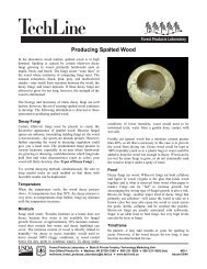
several times as well as some that have only been used a few times so they represent the typical mix ofbolsters. Measure more than 3 <strong>in</strong>. from the end of the bolster to avoid th<strong>in</strong> spots where the ends are broken orcompressed.Write down the 20 measurements and subtract the smallest from the largest to get the range of thicknesses.Rat<strong>in</strong>g4 - Range of bolster thickness is 1/8 <strong>in</strong>. (0.125 <strong>in</strong>.) or less3 - Range of bolster thickness is 1/4 <strong>in</strong>. (0.250 <strong>in</strong>.) or less2 - Range of bolster thickness is 3/8 <strong>in</strong>. (0.375 <strong>in</strong>.) or less1 - Range of bolster thickness is greater than 3/8 <strong>in</strong>. (0.375 <strong>in</strong>.)6c. Uniformity of sticker straightnessIn hardwood plants us<strong>in</strong>g semiautomatic stackers and stickers up to 7 or 8 ft <strong>in</strong> length, it is likely that a significantnumber of stickers will develop a noticeable amount of crook and/or k<strong>in</strong>k after repeated use. Stickers withmore than 3 <strong>in</strong>. of crook or side k<strong>in</strong>k (usually result<strong>in</strong>g from abnormal shr<strong>in</strong>kage around or near a knot), asmeasured by an imag<strong>in</strong>ary l<strong>in</strong>e drawn from one end to the other, should not be used. If the plant also usesshorter stickers <strong>in</strong> other stackers, predryers, or kilns, excessively crooked or k<strong>in</strong>ked stickers can be cut backto shorter lengths and utilized. If not, they should be discarded. Stickers with broken ends that are shorterthan the width of the package by 3 <strong>in</strong>. or more should not be used.Measure and record the departure from straightness of about 20 stickers hav<strong>in</strong>g noticeable amounts of crookor k<strong>in</strong>k.Rat<strong>in</strong>g4 - All stickers have less than 2 <strong>in</strong>. of crook or k<strong>in</strong>k3 - No more than 3 of 20 stickers have 2 <strong>in</strong>. or more of crook or k<strong>in</strong>k2 - No more than 5 of 20 stickers have 2 <strong>in</strong>. or more of crook or k<strong>in</strong>k1 - More than 5 of 20 stickers have 2 <strong>in</strong>. or more of crook or k<strong>in</strong>k6d. <strong>Lumber</strong> thickness variationSome variation <strong>in</strong> lumber thickness is to be expected from normal saw<strong>in</strong>g conditions. However, thicknessvariation greater than about 1/32 <strong>in</strong>. (0.031 <strong>in</strong>.) is usually a result of sawblade or feed problems <strong>in</strong> the sawmill.Thickness variation greater than this can have a major effect on predryer/kiln dry<strong>in</strong>g. Thick lumber dries moreslowly than th<strong>in</strong> lumber, so mix<strong>in</strong>g thick and th<strong>in</strong> lumber <strong>in</strong> a charge <strong>in</strong>creases MC variation. When thick andth<strong>in</strong> pieces are mixed across a course, the th<strong>in</strong>ner pieces are not restra<strong>in</strong>ed by the stickers. Th<strong>in</strong> lumber isthen free to cup, twist, and bow.Look at the ends of 15 packages of green lumber. All the boards should appear the same thickness with thestickers straight and touch<strong>in</strong>g all boards. Figure 1 illustrates how to evaluate thickness variation.Rat<strong>in</strong>g4 - All boards are uniform and touch<strong>in</strong>g stickers; stickers are not bent3 - Fewer than 10 boards per package do not touch stickers or stickers bend slightly over thick and th<strong>in</strong> lumber2 - Thickness variation is sufficient to bend stickers or show gaps more than 1/8 <strong>in</strong>. wide above boards1 - Thickness variation is great enough to make stack<strong>in</strong>g visibly irregular10
Figure 1. Evaluat<strong>in</strong>g lumber thickness variation (end view).6e. Pa<strong>in</strong>ted l<strong>in</strong>es on floor help proper position<strong>in</strong>g of lumber stacksEasily visible, pa<strong>in</strong>ted l<strong>in</strong>es or stripes on the floor are necessary to properly position the lumber stacks <strong>in</strong> thelarge open bays of the predryer. Otherwise it is difficult for the forklift operator to keep the piles aligned forproper air circulation.Rat<strong>in</strong>g4 - L<strong>in</strong>es easily seen and properly located2 - L<strong>in</strong>es obscure or worn away1 - No l<strong>in</strong>es on floor6f. Plenum width adequatewithThe placement of the stacks of lumber cannot encroach <strong>in</strong>to the fan plenum area—that is, cannot <strong>in</strong>terferethe proper air flow from the downdraft fans. Uniform air is a real concern <strong>in</strong> most predryers and considerableattention must be paid to make airflow as even as possible. Stacks may shift or lean dur<strong>in</strong>g dry<strong>in</strong>g, and thepossibility of this occur<strong>in</strong>g must be considered when load<strong>in</strong>g the predryer. Provide adequate room for movement.Plenum width should be no less than about the distance of the total pile height divided by five.Rat<strong>in</strong>g4 - Plenum width (<strong>in</strong> ft) is at least the total pile height (<strong>in</strong> ft) divided by 5, and fewer than 1 out of 25 top stacksis slightly <strong>in</strong> the plenum area3 - Plenum width (<strong>in</strong> ft) is at least the total pile height (<strong>in</strong> ft) divided by 5, and fewer than 1 out of 10 topstacks is slightly <strong>in</strong> the plenum area2 - Fewer than 1 out of 5 top stacks is slightly <strong>in</strong> the plenum area; plenum width is significantly less thansuggested1 - Many stacks are encroach<strong>in</strong>g on the plenum area11
6g. Spac<strong>in</strong>g between lumber pilesWhen two or more piles are on each side of the plenum, the suggested spac<strong>in</strong>g between adjacent lumber piles(edge to edge) is 4 <strong>in</strong>.Rat<strong>in</strong>g4 - Spac<strong>in</strong>g between adjacent lumber piles is 4 to 5 <strong>in</strong>., consistently3 - Spac<strong>in</strong>g between adjacent lumber piles is 3 to 8 <strong>in</strong>., consistently2 - More than 1 out of 4 adjacent piles is closer than 3 <strong>in</strong>.1 - Spac<strong>in</strong>g is often under 3 <strong>in</strong>.Operational Checks7. Dry-Bulb Temperatures7a. Appropriate range of operat<strong>in</strong>g temperaturesThe dry-bulb temperature should typically be between 80°F to 90°F, although a 95°F dry-bulb temperature, orhigher, may have to be used if outside temperature is warm and relative humidity (RH) is high. The absolutehumidity <strong>in</strong>side the predryer should be 5 gra<strong>in</strong>s per cubic foot wetter than outside the predryer. To achievethis difference, <strong>in</strong>crease the dry-bulb temperature <strong>in</strong> the predryer while keep<strong>in</strong>g the RH unchanged.Rat<strong>in</strong>gs4 - Dry-bulb temperature is between 80°F to 90°F (85°F to 95°F <strong>in</strong> summer)2 - Dry-bulb temperature is less than 80°F or more than 90°F7b. Accuracy of dry-bulb sensorsThe dry-bulb temperature <strong>in</strong>dicated on the recorder or readout <strong>in</strong>strument must be with<strong>in</strong> 1°F of the temperaturemeasured by a dry-bulb thermometer that has 1°F or 1/2°F divisions. A thermometer with only 2°F divisions,commonly used for kiln measurements, is not suitable. Each dry-bulb sensor location must be checkedseparately. Dry-bulb checks should be made every 3 months. If variation is noted, two additional read<strong>in</strong>gs onthe next 2 days should be taken to confirm the variation before any recalibration is done. In most predryers,temperatures should be measured under the downdraft fans just before the air enters the stack.Rat<strong>in</strong>g4 - Dry-bulb temperature is checked every 3 months and is with<strong>in</strong> 1°F of the temperature <strong>in</strong>dicated on therecorder/readout/controller for all sensors3 - Dry-bulb temperature is checked every 3 months and is with<strong>in</strong> 1°F of the temperature <strong>in</strong>dicated on therecorder for 80% of the sensors (2°F on others)2 - Dry-bulb temperature is checked at least every 6 months and is with<strong>in</strong> 2°F of the temperature <strong>in</strong>dicated onthe recorder for all sensors1 - Dry-bulb temperature is not checked regularly, or there is a difference of 2°F on one or more sensors7c. Hourly variation of dry-bulb temperatureThe recorded dry-bulb temperature on the chart should be at the desired level and should not vary throughoutthe day by more than ±1°F. Any greater variation should (a) be expla<strong>in</strong>ed and noted on the chart and/or(b) be an <strong>in</strong>dication of needed ma<strong>in</strong>tenance. Individual zones should vary no more than 3°F from each other.Rat<strong>in</strong>g4 - Variation with<strong>in</strong> ±1/2°F throughout the day3 - Variation with<strong>in</strong> ±1°F throughout the day2 - Variation with<strong>in</strong> ±2°F throughout the day1 - Variation more than 2°F throughout the day12
7d. Dry-bulb temperature variation with<strong>in</strong> control zoneThe dry-bulb temperature with<strong>in</strong> a control zone should not vary from the temperature at the control po<strong>in</strong>t morethan ±1°F. This is typically checked by measur<strong>in</strong>g the temperature every 6 to 8 ft along the plenum under thedowndraft fans.Rat<strong>in</strong>g4 - Variation with<strong>in</strong> ±1°F2 - Variation with<strong>in</strong> ±2°F1 - Variation more than ±2°F7e. Select<strong>in</strong>g “controll<strong>in</strong>g” zone dry-bulb temperature for the predryerThe controll<strong>in</strong>g zone dry-bulb sensor should be the one located <strong>in</strong> the zone with the wettest lumber, except <strong>in</strong>extenuat<strong>in</strong>g circumstances.Rat<strong>in</strong>g4 - Controll<strong>in</strong>g bulb/sensor is where the wettest lumber is located1 - Controll<strong>in</strong>g bulb/sensor is NOT where the wettest lumber is located7f. Possible shut-down of predryer when ma<strong>in</strong> door is openIf dry-bulb temperature changes by more than 2°F when the ma<strong>in</strong> door(s) of the predryer are opened, theentire unit should be shut down when the door is open.Rat<strong>in</strong>g4 - Fans are turned off when ma<strong>in</strong> door is open and dry-bulb temperature changes by 2°F2 - Fans are turned off when ma<strong>in</strong> door is open and dry-bulb temperature changes by 4°F1 - Fans always run when ma<strong>in</strong> door is open8. Wet-Bulb Temperatures, RH, or EMC8a. Accuracy of wet-bulb sensorThe wet-bulb temperature <strong>in</strong>dicated on the recorder or readout <strong>in</strong>strument must yield a RH <strong>in</strong> the predryerwith<strong>in</strong> ±2% RH of the value obta<strong>in</strong>ed from a sl<strong>in</strong>g psychrometer that has thermometers with 1°F or 1/2°Fdivisions. Because of the high speed of readout, a digital hygrometer can be used to <strong>in</strong>dicate %RH. Thishygrometer should be checked for accuracy us<strong>in</strong>g a 1°F sl<strong>in</strong>g psychrometer every 3 months. Each sensorlocation should be checked separately. If variation is noted, read<strong>in</strong>gs on at least three different days shouldbe noted to confirm the variation before recalibration is done.Rat<strong>in</strong>g4 - Wet-bulb sensors are checked every 3 months and are with<strong>in</strong> ±2% RH3 - Wet-bulb sensors are checked every 3 months and are with<strong>in</strong> ±4% RH2 - Wet-bulb sensors are checked less frequently than every 3 months and are with<strong>in</strong> ±2% RH1 - Wet-bulb sensors are rarely checked or are out of calibration8b. Accuracy of relative humidity or EMC sensor(s)The relative humidity (RH) <strong>in</strong>dicated on the recorder or readout <strong>in</strong>strument must be with<strong>in</strong> ±3% RH of the RHmeasured by a sl<strong>in</strong>g psychrometer that has thermometers with 1°F or 1/2°F divisions. A thermometer withonly 2°F divisions, commonly used with kiln measurements, is not suitable. Alternatively, the RH can bemeasured with a solid state direct RH read<strong>in</strong>g device whose calibration has been verified with<strong>in</strong> the last3 months. Relative humidity checks should be made once every month. If variation is noted, two additional13
ead<strong>in</strong>gs on the next 2 days should be taken to confirm the variation before any recalibration is done. Inmost predryers, RH should be measured under the downdraft fans, just before the air enters the stack.Rat<strong>in</strong>g4 - RH sensors are checked monthly and are with<strong>in</strong> ±2% RH3 - RH sensors are checked monthly and are with<strong>in</strong> ±4% RH2 - RH sensors are checked less frequently than once a month and are with<strong>in</strong> 2% RH1 - RH sensors are rarely checked or are out of calibration8c. Daily variation of wet-bulb temperature/RH/EMCThe wet-bulb temperature (RH or EMC) recorded on the chart or <strong>in</strong>dicated on the readout <strong>in</strong>strument shouldbe at the desired level and should not vary throughout the day by more than ±1°F (±3% RH or ±1% EMC).Variation(s) greater than this should (a) be expla<strong>in</strong>ed and noted on the chart and/or (b) be an <strong>in</strong>dication ofneeded ma<strong>in</strong>tenance. Individual zones should vary no more than 5% RH from each other.Rat<strong>in</strong>g4 - Daily variation is with<strong>in</strong> the limits specified2 - Daily variation is with<strong>in</strong> twice the limits specified1 - Daily variation is greater than twice the limits specified8d. Possible shut-down of fans when ma<strong>in</strong> door is openIf the RH <strong>in</strong> the predryer changes by more than 5% when the ma<strong>in</strong> door(s) is opened, the entire unit should beshut down when the door(s) is open.Rat<strong>in</strong>g4 - Fans are turned off when ma<strong>in</strong> door is open and RH changes by 5% RH or 1-1/2% EMC2 - Fans are turned off when ma<strong>in</strong> door is open and RH changes by 10% RH or 3% EMC1 - Fans always run when ma<strong>in</strong> door is open8e. RH limits <strong>in</strong> predryer when load<strong>in</strong>g wet lumberWhen wet lumber is brought <strong>in</strong>to the predryer, the RH should not exceed the desired value by more than 3%RH. If the predryer is too humid, the <strong>in</strong>com<strong>in</strong>g lumber should be brought <strong>in</strong> over a several day <strong>in</strong>terval.Rat<strong>in</strong>g4 - Actual RH exceeds desired value by 3% or less2 - Actual RH exceeds desired value by 3% to 5%1 - Actual RH exceeds desired value by more than 5%9. Fan Operation and Air Velocity9a. Fans turn<strong>in</strong>g for proper airflowTo dry lumber, air of controlled temperature and humidity must be passed uniformly over the surface of thelumber. This circulat<strong>in</strong>g air is the “workhorse” of the predryer or dry kiln. As such, the air performs two tasks: itcarries heat to the wood to evaporate the water and it removes the evaporated water vapor. An adequatevolume of air must pass uniformly through the courses of lumber to accomplish these two tasks. In thepredryer, all fans should be operat<strong>in</strong>g, have the same rpm, and have the same blade pitch.14
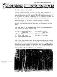
Rat<strong>in</strong>g4 - Fans are checked for proper operation (rotation, rpm, pitch) once a year, and all fans are observed eachweek to determ<strong>in</strong>e if all fans are operat<strong>in</strong>g3 - Fans are checked for proper operation (see above) once a year, and weekly check <strong>in</strong>dicates all but one fanis operat<strong>in</strong>g2 - Fans are checked for proper operation (see above) once a year, and weekly check <strong>in</strong>dicates all but twofans are operat<strong>in</strong>g1 - Fans are not checked frequently; only when problems arise9b. Average air velocity through the loadThe air velocity through the load should be measured on the leav<strong>in</strong>g air side of a downdraft predryer <strong>in</strong> at least10 locations per bay and the values averaged. The average should be 125 ft/m<strong>in</strong> to assure good uniformdry<strong>in</strong>g. This should be checked for every new load of lumber after the predryer is completely loaded.Rat<strong>in</strong>g4 - Air velocity is checked on each load and is 100 to 150 ft/m<strong>in</strong> on the average3 - Air velocity is checked on each load and is 75 to 175 ft/m<strong>in</strong> on the average2 - Air velocity is checked occasionally and is 75 to 175 ft/m<strong>in</strong> on the average1 - Air velocity is rarely checked9c. Air velocity uniformity/variationIn addition to average velocity of air through the load, the variation around the average is also important. Airvelocity through the lumber stacks, as measured on the exit side of the load, should be as uniform as possible.Although some variation is to be expected, an ideal value is ±25 ft/m<strong>in</strong>; the maximum suggested variationis ±50 ft/m<strong>in</strong>. This uniformity is required vertically (at different height levels <strong>in</strong> the piles) as well as alongthe length of the predryer.Rat<strong>in</strong>g4 Air velocity measurements do not vary by more than ±25 ft/m<strong>in</strong>3 - Air velocity measurements do not vary by more than ±50 ft/m<strong>in</strong>2 - Air velocity measurements do not vary by more than ±75 ft/m<strong>in</strong>1 - Air velocity measurements vary by more than ±75 ft/m<strong>in</strong>9d. Use of baffles <strong>in</strong> plenum spaceFlat baffles should be used <strong>in</strong> the plenum space of downdraft predryers to assist <strong>in</strong> obta<strong>in</strong><strong>in</strong>g uniform air flow.Two baffles may be required when stacks are more than 18 ft high. If baffles are not used, piles should bereloaded after 2 weeks, with packages reversed top to bottom and bottom to top (Fig. 2).Rat<strong>in</strong>g4 - Plenum baffle always used3 - Plenum baffle usually used1 - Plenum baffle seldom or never used9e. Use of end bafflesEnd baffles should be used at the end of the piles that are not with<strong>in</strong> 2 ft of the end of another pile to force airthrough the piles rather than allow<strong>in</strong>g it to go around.Rat<strong>in</strong>g4 - End baffles always used1 - End baffles NOT used15
Figure 2. Placement of baffles <strong>in</strong> plenum space.9f. Use of tapered bolstersIn a predryer design by Imrie 3 , best performance is obta<strong>in</strong>ed by us<strong>in</strong>g tapered bolsters. This permits theplenum to be wider at the top than at the floor, by tilt<strong>in</strong>g the piles slightly.Rat<strong>in</strong>g4 - Tapered bolsters always used1 - Tapered bolsters NOT used9g. Burlap wrap for thick lumberThick lumber (8/4 and thicker) of refractory species, such as oak and beech, may require wrapp<strong>in</strong>g <strong>in</strong> burlapcloth or plastic “nett<strong>in</strong>g fabric” to reduce airflow and rapid dry<strong>in</strong>g of the surface that may produce surfacecheck<strong>in</strong>g.Rat<strong>in</strong>g4 - Burlap wrap used as appropriate1 - Burlap wrap rarely or never used9h. Fan control with<strong>in</strong> a control zoneAll predryers should have the fans wired such that all fans <strong>in</strong> a particular control zone may be turned off ifdesired. This slows dry<strong>in</strong>g of the lumber and avoids <strong>in</strong>creas<strong>in</strong>g RH. The procedure of turn<strong>in</strong>g every other fanon or off is not recommended.Rat<strong>in</strong>g4 - Fans <strong>in</strong> a zone can be turned on/off easily3 - Fans <strong>in</strong> a zone can be turned on/off with difficulty1 - Fans <strong>in</strong> a zone cannot be turned on/off <strong>in</strong>dependently_____________________________3The use of trade or firm names <strong>in</strong> this publication is for reader <strong>in</strong>formation and does not imply endorsement by theU.S. Department of Agriculture of any product or service.16
Monitor<strong>in</strong>g <strong>Dry<strong>in</strong>g</strong> Rate and Degrade Formation10a. Use of sample boards to monitor dry<strong>in</strong>g rateThe dry<strong>in</strong>g rate of the lumber, us<strong>in</strong>g properly prepared sample boards (see 2b.), should be checked on a dailybasis, especially with greener lumber. Adjustment of conditions <strong>in</strong> the predryer may be required.Rat<strong>in</strong>g4 - Sample boards are used and are checked three times per week3 - Sample boards are used and are checked once a week2 - Sample boards are seldom used1 - Sample boards are never used10b. Monitor<strong>in</strong>g for presence of surface check<strong>in</strong>g on <strong>in</strong>com<strong>in</strong>g lumberIncom<strong>in</strong>g oak and beech lumber that is not green-from-the-saw should be checked for the presence of exist<strong>in</strong>gsurface checks before or as it is be<strong>in</strong>g loaded <strong>in</strong> the predryer. This can be done by cutt<strong>in</strong>g a small section (atleast 12 <strong>in</strong>.) from the end of the board (Fig. 3).Rat<strong>in</strong>g4 - Oak and beech lumber are always checked for surface checks3 - Oak and beech lumber are often checked for surface checks1 - Oak and beech lumber are seldom checked for surface checksFigure 3. Inspect for surface checks by cutt<strong>in</strong>g a small section from end of board.17
10c. Record<strong>in</strong>g of f<strong>in</strong>al moisture contentWhen target moisture content (MC) has been reached or when lumber is removed from the predryer to fill adry kiln, the current or f<strong>in</strong>al moisture content should be measured and recorded. Any variation of moisturecontent with respect to location <strong>in</strong> the predryer should be noted.Rat<strong>in</strong>g4 - At least five MC read<strong>in</strong>gs are taken and recorded for each load3 - MC read<strong>in</strong>gs are occasionally taken and recorded1 - F<strong>in</strong>al MC is not sampled10d. Initial set-po<strong>in</strong>t conditions of dry kiln for lumber from predryerThe <strong>in</strong>itial conditions of the dry kiln where the lumber from the predryer will be dried to f<strong>in</strong>al target shouldgenerally be 1% EMC drier than the average moisture content value of the lumber com<strong>in</strong>g from the predryer.Rat<strong>in</strong>g4 - Initial condition <strong>in</strong> the kiln is regularly 1% EMC below that <strong>in</strong> the predryer3 - Initial condition <strong>in</strong> the kiln is usually 1% EMC below that <strong>in</strong> the predryer1 - Initial condition <strong>in</strong> the kiln is not related to EMC <strong>in</strong> the predryer18
Checklist for <strong>Quality</strong> <strong>Dry<strong>in</strong>g</strong> <strong>in</strong> a <strong>Hardwood</strong> <strong>Lumber</strong> <strong>Predryer</strong>Standard Operat<strong>in</strong>g PracticesLow High1a. Proper location of dry-bulb sensors .............................................................................................. 1 2 3 4Rat<strong>in</strong>g4 - Dry-bulb sensors located <strong>in</strong> the enter<strong>in</strong>g air stream3 - Dry-bulb sensors located near the circulat<strong>in</strong>g fans2 - Dry-bulb sensors located more than 3 ft from the fans and not <strong>in</strong> the enter<strong>in</strong>g air stream1 - Dry-bulb sensors located close to the wall or roof1b. Influence of side vents on recorded dry-bulb temperatures ......................................................... 2 4Rat<strong>in</strong>g4 - The dry-bulb sensor located on the west or north side of dryer is with<strong>in</strong> 1°F of dry-bulbtemperatures on the east or south side most of the time2 - The dry-bulb sensor located on the west or north side of dryer is more than 1°F lowerthan the dry-bulb temperatures on the east or south side most of the time1c. Proper location of the relative humidity (RH) sensor .................................................................... 1 2 3 4Rat<strong>in</strong>g4 - RH sensors located <strong>in</strong> the enter<strong>in</strong>g air stream3 - RH sensors located near the circulat<strong>in</strong>g fans2 - RH sensors located more than 3 ft from the fans and not <strong>in</strong> the enter<strong>in</strong>g air stream1 - RH sensors located close to the wall or roof1d. Influence of side vents on recorded RH values ............................................................................ 2 4Rat<strong>in</strong>g4 - The RH on the west or north side should be with<strong>in</strong> 2% RH of the RH on the east orsouth side most of the time2 - The RH on the west or north side is frequently more than 2% higher than on the eastor south side1e. Use of wet-bulbs to determ<strong>in</strong>e RH values .................................................................................... 1 2 3 4Rat<strong>in</strong>g4 - Wick changed weekly, water is clean, about 80°F, and air velocity across wick isabout 600 fpm3 - Wick changed weekly, water is clean, about 80°F, and air velocity across wick isabout 400 fpm2 - Wick changed weekly, water is clean, about 80°F, and air velocity across wick isabout 200 fpm1 - Wick is changed less than once per week1f. Use of EMC sensor to determ<strong>in</strong>e humidity <strong>in</strong> predryer ................................................................. 1 2 3 4Rat<strong>in</strong>g4 - EMC wafer is changed weekly; calibration is confirmed monthly3 - EMC wafer is changed weekly; calibration is rarely checked2 - EMC wafer is changed less than once a week; calibration is confirmed monthly1 - EMC wafer is rarely checked19
Low High1g. Air supply to control <strong>in</strong>struments and operat<strong>in</strong>g valves checked at regular <strong>in</strong>tervals .................. 1 2 3 4Rat<strong>in</strong>g4 - Air compressor is checked and dra<strong>in</strong>ed daily3 - Air compressor is <strong>in</strong>spected on some schedule, but at least monthly2 - Air compressor is <strong>in</strong>spected only when a problem is suspected1 - Air compressor is <strong>in</strong>spected only when the controller or air supply does not work1h. Drip pans positioned below roof vents ......................................................................................... 2 4Rat<strong>in</strong>g4 - Drip pans are positioned below all roof vents, and are of sufficient capacity toreta<strong>in</strong> all condensate or have dra<strong>in</strong>s provided2 - No drip pans present1i. Condensation of water on predryer floor ....................................................................................... 1 2 3 4Rat<strong>in</strong>g4 - Condensation on the floor is rarely or never seen3 - On the coldest days, a little condensation may be seen2 - Occasionally a little condensation may be seen1 - Wet spots are frequently seen1j. Removal of dirt and debris from predryer floor ............................................................................. 1 2 3 4Rat<strong>in</strong>g4 - Floor cleaned weekly3 - Floor cleaned once a month2 - Floor cleaned two times a year1 - Floor never cleaned1k. Roof is free of leaks ..................................................................................................................... 1 2 4Rat<strong>in</strong>g4 - No leaks seen2 - Roof leaks on days with heavy ra<strong>in</strong>s1 - Roof leaks frequently1l. Traps checked for proper operation and plumbed for ease of check<strong>in</strong>g ....................................... 1 3 4Rat<strong>in</strong>g4 - Each bank of coils has its own trap and check valve3 - Each ma<strong>in</strong> heat coil is trapped, but side vent heaters are not <strong>in</strong>dividually trapped1 - Several banks of coils use one trap or check valves not <strong>in</strong>stalled1m. Circulat<strong>in</strong>g fans turn<strong>in</strong>g <strong>in</strong> proper direction and lubricated properly ............................................ 1 2 3 4Rat<strong>in</strong>g4 - All fan motors turn the same direction and are lubricated at manufacturersspecified <strong>in</strong>tervals3 - All fan motors turn the same direction and are NOT lubricated at manufacturersspecified <strong>in</strong>tervals2 - Fans seldom checked to see if all runn<strong>in</strong>g and turn<strong>in</strong>g <strong>in</strong> same direction1 - Fans not checked and are lubricated only when problem occurs1n. Exhaust fans turn<strong>in</strong>g for proper airflow and lids clos<strong>in</strong>g properly ................................................ 2 4Rat<strong>in</strong>g4 - Exhaust fans and lids checked monthly; lubricated as needed2 - Exhaust fans and lids not checked monthly and/or not lubricated20
Low High1o. Proper function<strong>in</strong>g of side vents ................................................................................................... 1 2 3 4Rat<strong>in</strong>g4 - Proper operation of side vents checked weekly3 - Proper operation of side vents checked monthly2 - Proper operation of side vents checked semi-annually1 - Proper operation of side vents checked only when problems occur1p. General build<strong>in</strong>g <strong>in</strong>spection .......................................................................................................... 1 2 3 4Rat<strong>in</strong>g4 - Thorough check and report provided to management every 6 weeks3 - Thorough check and report provided to management every 3 months2 - Inspection and report provided annually1 - Not <strong>in</strong>spected; no report prepared1q. Heat<strong>in</strong>g coils clean and free of debris .......................................................................................... 1 3 4Rat<strong>in</strong>g4 - Coils clean and free of obstructions3 - Coils fairly clean (slight rust) and free of obstructions1 - Coils with heavy rust; coils blocked with debris2. Moisture Content Monitor<strong>in</strong>g and Recordkeep<strong>in</strong>g2a. Knowledge of history of lumber before go<strong>in</strong>g <strong>in</strong>to predryer .......................................................... 1 3 4Rat<strong>in</strong>g4 - History of the lumber and the MC of the lumber go<strong>in</strong>g <strong>in</strong>to the predryer are known3 - You can reconstruct the history and have taken a few moisture read<strong>in</strong>gs1 - No effort was made to learn the history or to determ<strong>in</strong>e the MC2b. Use of sample boards (kiln samples) to monitor moisture content .............................................. 1 2 3 4Rat<strong>in</strong>g4 - Sample boards are always selected, prepared, placed, and used as recommended<strong>in</strong> Chapter 6 of the DKOM3 - Sample boards are usually used, with m<strong>in</strong>imal attention to selection and usuallyonly 2 or 3 boards used per 100,000 board feet2 - Sample boards are rarely used1 - Sample boards are never used2c. Disposition of lumber after removal from predryer ....................................................................... 1 2 3 4Rat<strong>in</strong>g4 - <strong>Lumber</strong> always goes directly to the kiln3 - <strong>Lumber</strong> always goes to kiln or to unheated covered storage build<strong>in</strong>g2 - <strong>Lumber</strong> usually goes to kiln or to unheated storage build<strong>in</strong>g1 - <strong>Lumber</strong> usually goes to unprotected storage2d. Identification of packages of lumber <strong>in</strong> predryer .......................................................................... 1 3 4Rat<strong>in</strong>g4 - Individual packages are monitored3 - Entire or partial kiln loads are monitored as a group1- No records are regularly ma<strong>in</strong>ta<strong>in</strong>ed21
3. Learn<strong>in</strong>g OpportunitiesLow High3a. Opportunities to visit other sites and meet other operators ......................................................... 1 2 3 4Rat<strong>in</strong>g4 - Visit other predryer sites three or more times per year3 - Visit other predryer sites twice a year2 - Visit other predryer sites once a year1 - Never visit other predryer sites3b. Attend dry kiln association meet<strong>in</strong>gs and dry<strong>in</strong>g workshops ....................................................... 1 2 3 4Rat<strong>in</strong>g4 - Attend dry kiln association meet<strong>in</strong>gs yearly and have attended at least one workshop3 - Regularly attend meet<strong>in</strong>gs but have never been to a workshop2 - Attend meet<strong>in</strong>gs every 2 or 3 years1 - Never attend meet<strong>in</strong>gs or workshopsControl Room4. Environmental Conditions <strong>in</strong> Control Room Appropriate4a. Temperature and relative humidity controlled for good work<strong>in</strong>g conditions ofpersonnel and control <strong>in</strong>strumentation ........................................................................................ 1 3 4Rat<strong>in</strong>g4 - Control room is always well heated and air conditioned3 - Control room is well heated and air conditioned most days1 - Temperature and RH <strong>in</strong> control room considered not important5. Instrument Charts5a. Correct <strong>in</strong>strument charts are used .............................................................................................. 1 4Rat<strong>in</strong>g4 - Chart paper matches record<strong>in</strong>g <strong>in</strong>strument1 - Wrong chart paper is used5b. Chart record is clear and legible .................................................................................................. 1 4Rat<strong>in</strong>g4 - Charts are changed weekly with clear legible trac<strong>in</strong>gs1 - Charts are changed <strong>in</strong>frequently, overwritten, provide no useful record<strong>in</strong>g of conditions<strong>Lumber</strong> Stack<strong>in</strong>g and Load<strong>in</strong>g of <strong>Predryer</strong>6. Sticker and Bolster Thickness6a. Sticker thickness uniformity ......................................................................................................... 1 2 3 4Rat<strong>in</strong>g4 - Range of sticker thickness is 1/32 <strong>in</strong>. (0.031 <strong>in</strong>.) or less3 - Range of sticker thickness is 1/16 <strong>in</strong>. (0.063 <strong>in</strong>.) or less2 - Range of sticker thickness is 1/8 <strong>in</strong>. (0.125 <strong>in</strong>.) or less1 - Range of sticker thickness is greater than 1/8 <strong>in</strong>. (0.125 <strong>in</strong>.)22
Low High6b. Bolster thickness uniformity ......................................................................................................... 1 2 3 4Rat<strong>in</strong>g4 - Range of bolster thickness is 1/8 <strong>in</strong>. (0.125 <strong>in</strong>.) or less3 - Range of bolster thickness is 1/4 <strong>in</strong>. (0.250 <strong>in</strong>.) or less2 - Range of bolster thickness is 3/8 <strong>in</strong>. (0.375 <strong>in</strong>.) or less1 - Range of bolster thickness is greater than 3/8 <strong>in</strong>. (0.375 <strong>in</strong>.)6c. Uniformity of sticker straightness ................................................................................................. 1 2 3 4Rat<strong>in</strong>g4 - All stickers have less than 2 <strong>in</strong>. of crook or k<strong>in</strong>k3 - No more than 3 of the 20 stickers have 2 <strong>in</strong>. or more of crook or k<strong>in</strong>k2 - No more than 5 of the 20 stickers have 2 <strong>in</strong>. or more of crook or k<strong>in</strong>k1 - More than 5 of the 20 stickers have 2 <strong>in</strong>. or more of crook or k<strong>in</strong>k6d. <strong>Lumber</strong> thickness variation .......................................................................................................... 1 2 3 4Rat<strong>in</strong>g4 - All boards are uniform and touch<strong>in</strong>g stickers; stickers are not bent3 - Fewer than 10 boards per package do not touch stickers or stickers bendslightly over thick or th<strong>in</strong> lumber2 - Thickness variation is sufficient to bend stickers or show gaps more than1/8 <strong>in</strong>. wide above boards1 - Thickness variation is great enough to make stack<strong>in</strong>g visibly irregular6e. Pa<strong>in</strong>ted l<strong>in</strong>es on floor help proper position<strong>in</strong>g of stacks ............................................................... 1 2 4Rat<strong>in</strong>g4 - L<strong>in</strong>es easily seen and properly located2 - L<strong>in</strong>es obscure or worn away1 - No l<strong>in</strong>es on floor6f. Plenum width adequate ................................................................................................................ 1 2 3 4Rat<strong>in</strong>g4 - Plenum width (<strong>in</strong> ft) is at least the total pile height (<strong>in</strong> ft) divided by 5 andfewer than 1 out of 25 top stacks is slightly <strong>in</strong> the plenum area3 - Plenum width (<strong>in</strong> ft) is at least the total pile height (<strong>in</strong> ft) divided by 5 andfewer than 1 out of 10 top stacks is slightly <strong>in</strong> the plenum area2 - Fewer than 1 out of 5 top stacks is slightly <strong>in</strong> the plenum area; plenum width issignificantly less than suggested1 - Many stacks are encroach<strong>in</strong>g on the plenum area6g. Spac<strong>in</strong>g between lumber piles ..................................................................................................... 1 2 3 4Rat<strong>in</strong>g4 - Spac<strong>in</strong>g between adjacent lumber piles is 4 to 5 <strong>in</strong>., consistently3 - Spac<strong>in</strong>g between adjacent lumber piles is 3 to 8 <strong>in</strong>., consistently2 - More than 1 out of 4 adjacent piles is closer than 3 <strong>in</strong>.1 - Spac<strong>in</strong>g is often under 3 <strong>in</strong>.Operational Checks7. Dry-Bulb Temperatures7a. Typical range of operat<strong>in</strong>g temperatures ..................................................................................... 2 4Rat<strong>in</strong>g4 - Dry-bulb temperature is between 80°F to 90°F (85°F to 95°F <strong>in</strong> summer)2 - Dry-bulb temperature is less than 80°F or more than 90°F23
Low High7b. Accuracy of dry-bulb sensors ....................................................................................................... 1 2 3 4Rat<strong>in</strong>g4 - Dry-bulb temperature is checked every 3 months and is with<strong>in</strong> 1°F of thetemperature <strong>in</strong>dicated on the recorder/readout/controller for all sensors3 - Dry-bulb temperature is checked every 3 months and is with<strong>in</strong> 1°F of thetemperature <strong>in</strong>dicated on the recorder for 80% of the sensors (2°F on others)2 - Dry-bulb temperature is checked at least every 6 months and is with<strong>in</strong> 2°F ofthe temperature <strong>in</strong>dicated on the recorder for all sensors1 - Dry-bulb temperature is not checked regularly, or there is a difference of2°F on one or more sensors7c. Daily variation of dry-bulb temperature ........................................................................................ 1 2 3 4Rat<strong>in</strong>g4 - Variation with<strong>in</strong> ±1/2°F throughout the day3 - Variation with<strong>in</strong> ±1°F throughout the day2 - Variation with<strong>in</strong> ±2°F throughout the day1 - Variation more than 2°F throughout the day7d. Dry-bulb temperature variation with<strong>in</strong> control zone ...................................................................... 1 2 4Rat<strong>in</strong>g4 - Variation with<strong>in</strong> ±1°F2 - Variation with<strong>in</strong> ±2°F1 - Variation more than ±2°F7e. Select<strong>in</strong>g “controll<strong>in</strong>g zone” dry-bulb temperature ....................................................................... 1 4Rat<strong>in</strong>g4 - Controll<strong>in</strong>g bulb/sensor is where the wettest lumber is located1 - Controll<strong>in</strong>g bulb/sensor is NOT where the wettest lumber is located7f. Possible shut-down of predryer when ma<strong>in</strong> door is open ............................................................. 1 2 4Rat<strong>in</strong>g4 - Fans are turned off when ma<strong>in</strong> door is open and dry-bulb temperature changes by 2°F2 - Fans are turned off when ma<strong>in</strong> door is open and dry-bulb temperature changes by 4°F1 - Fans always run when ma<strong>in</strong> door is open8. Wet-Bulb Temperatures, RH, or EMC8a. Accuracy of wet-bulb sensor ........................................................................................................ 1 2 3 4Rat<strong>in</strong>g4 - Wet-bulb sensors are checked every 3 months and are with<strong>in</strong> ±2% RH3 - Wet-bulb sensors are checked every 3 months and are with<strong>in</strong> ±4% RH2 - Wet-bulb sensors are checked less frequently than every 3 months and are with<strong>in</strong> ±2% RH1 - Wet-bulb sensors are rarely checked or are out of calibration8b. Accuracy of relative humidity sensor(s) ....................................................................................... 1 2 3 4Rat<strong>in</strong>g4 - RH sensors are checked monthly and are with<strong>in</strong> ±2% RH3 - RH sensors are checked monthly and are with<strong>in</strong> ±4% RH2 - RH sensors are checked less frequently than once a month and are with<strong>in</strong> ±2% RH1 - RH sensors are rarely checked or are out of calibration24
Low High8c. Daily variation of wet-bulb temperature ........................................................................................ 1 2 4Rat<strong>in</strong>g4 - Daily variation is with<strong>in</strong> the limits specified2 - Daily variation is with<strong>in</strong> twice the limits specified1 - Daily variation is greater than twice the limits specified8d. Possible shut-down of fans when ma<strong>in</strong> door is open ................................................................... 1 2 4Rat<strong>in</strong>g4 - Fans are turned off when ma<strong>in</strong> door is open and RH changes by 5% RH or 1-1/2% EMC2 - Fans are turned off when ma<strong>in</strong> door is open and RH changes by 10% RH or 3% EMC1 - Fans always run when ma<strong>in</strong> door is open8e. RH limits <strong>in</strong> predryer when load<strong>in</strong>g wet lumber ............................................................................ 1 2 4Rat<strong>in</strong>g4 - Actual RH exceeds desired value by 3% or less2 - Actual RH exceeds desired value by 3% to 5%1 - Actual RH exceeds desired value by more than 5%9. Fan Operation and Air Velocity9a. Fans turn<strong>in</strong>g for proper airflow ..................................................................................................... 1 2 3 4Rat<strong>in</strong>g4 - Fans are checked for proper operation (rotation, rpm, pitch) once a year, andall fans are observed each week to determ<strong>in</strong>e if all fans are operat<strong>in</strong>g3 - Fans are checked for proper operation (see above) once a year, and weeklycheck <strong>in</strong>dicates all but one fan is operat<strong>in</strong>g2 - Fans are checked for proper operation (see above) once a year, and weeklycheck <strong>in</strong>dicates all but two fans are operat<strong>in</strong>g1 - Fans are not checked frequently; only when problems arise9b. Average air velocity through the load ........................................................................................... 1 2 3 4Rat<strong>in</strong>g4 - Air velocity is checked on each load and is 100 to 150 ft/m<strong>in</strong> on the average3 - Air velocity is checked on each load and is 75 to 175 ft/m<strong>in</strong> on the average2 - Air velocity is checked occasionally and is 75 to 175 ft/m<strong>in</strong> on the average1 - Air velocity is rarely checked9c. Air velocity uniformity/variation through the stacks ...................................................................... 1 2 3 4Rat<strong>in</strong>g4 - Air velocity measurements do not vary by more than +25 ft/m<strong>in</strong>3 - Air velocity measurements do not vary by more than +50 ft/m<strong>in</strong>2 - Air velocity measurements do not vary by more than +75 ft/m<strong>in</strong>1 - Air velocity measurements vary by more than +75 ft/m<strong>in</strong>9d. Use of baffles <strong>in</strong> plenum space .................................................................................................... 1 3 4Rat<strong>in</strong>g4 - Plenum baffle always used3 - Plenum baffle usually used1 - Plenum baffle seldom or never used9e. Use of end baffles ........................................................................................................................ 1 4Rat<strong>in</strong>g4 - End baffles always used1 - End baffles NOT used25
Low High9f. Use of tapered bolsters ................................................................................................................. 1 4Rat<strong>in</strong>g4 - Tapered bolsters always used1 - Tapered bolsters NOT used9g. Burlap wrap for thick lumber ........................................................................................................ 1 4Rat<strong>in</strong>g4 - Burlap wrap used as appropriate1 - Burlap wrap rarely or never used9h. Fan control with<strong>in</strong> a control zone ................................................................................................. 1 3 4Rat<strong>in</strong>g4 - Fans <strong>in</strong> a zone can be turned on/off easily3 - Fans <strong>in</strong> a zone can be turned on/off with difficulty1 - Fans <strong>in</strong> a zone cannot be turned on/off <strong>in</strong>dependentlyMonitor<strong>in</strong>g <strong>Dry<strong>in</strong>g</strong> Rate and Degrade Formation10a. Use of sample boards to monitor dry<strong>in</strong>g rate.............................................................................. 1 2 3 4Rat<strong>in</strong>g4 - Sample boards are used and are checked three times per week3 - Sample boards are used and are checked once a week2 - Sample boards are seldom used1 - Sample boards are never used10b. Monitor<strong>in</strong>g presence of surface check<strong>in</strong>g on <strong>in</strong>com<strong>in</strong>g lumber.................................................. 1 3 4Rat<strong>in</strong>g4 - Oak and beech lumber are always checked for surface checks3 - Oak and beech lumber are often checked for surface checks1 - Oak and beech lumber are seldom checked for surface checks10c. Record<strong>in</strong>g of f<strong>in</strong>al moisture content ............................................................................................ 1 3 4Rat<strong>in</strong>g4 - At least five MC read<strong>in</strong>gs are taken and recorded for each load3 - MC read<strong>in</strong>gs are occasionally taken and recorded1 - F<strong>in</strong>al MC is not sampled10d. Initial set-po<strong>in</strong>t conditions of dry kiln for lumber from predryer .................................................. 1 3 4Rat<strong>in</strong>g4 - Initial condition <strong>in</strong> the kiln is regularly 1% EMC below that <strong>in</strong> the predryer3 - Initial condition <strong>in</strong> the kiln is usually 1% EMC below that <strong>in</strong> the predryer1 - Initial condition <strong>in</strong> the kiln is not related to EMC <strong>in</strong> the predryer26
Appendix 1Summary Checklist for <strong>Quality</strong> <strong>Dry<strong>in</strong>g</strong><strong>in</strong> a <strong>Hardwood</strong> <strong>Lumber</strong> <strong>Predryer</strong>Appendix 1 conta<strong>in</strong>s all the items from the checklist and <strong>in</strong> the same order; only the rat<strong>in</strong>g system has been omitted.This will shorten the number of checklist pages, and fil<strong>in</strong>g the checklist with the kiln records will require less space.27
<strong>Predryer</strong>________________________Summary Checklist for <strong>Quality</strong> <strong>Dry<strong>in</strong>g</strong> <strong>in</strong> a <strong>Hardwood</strong> <strong>Lumber</strong> <strong>Predryer</strong>StandardOperat<strong>in</strong>gPracticesDate___________________________1. Ma<strong>in</strong>tenance and InspectionLow High1a. Proper location of dry-bulb sensors ............................................................................................ 1 2 3 41b. Influence of side vents on recorded dry-bulb temperatures ........................................................ 2 41c. Proper location of the relative humidity (RH) sensor ................................................................... 1 2 3 41d. Influence of side vents on recorded RH values .......................................................................... 2 41e. Use of wet-bulbs to determ<strong>in</strong>e RH values .................................................................................. 1 2 3 41f. Use of EMC sensor to determ<strong>in</strong>e humidity <strong>in</strong> predryer ............................................................... 1 2 3 41g. Air supply to control <strong>in</strong>struments and operat<strong>in</strong>g valves checked at regular <strong>in</strong>tervals ................. 1 2 3 41h. Drip pans positioned below roof vents ........................................................................................ 2 41i. Condensation of water on predryer floor ..................................................................................... 1 2 3 41j. Removal of dirt and debris from predryer floor ............................................................................ 1 2 3 41k. Roof is free of leaks .................................................................................................................... 1 2 41l. Traps checked for proper operation and plumbed for ease of check<strong>in</strong>g ..................................... 1 3 41m. Circulat<strong>in</strong>g fans turn<strong>in</strong>g <strong>in</strong> proper direction and lubricated properly ............................................ 1 2 3 41n. Exhaust fans turn<strong>in</strong>g for proper airflow and lids clos<strong>in</strong>g properly ................................................ 2 41o. Proper function<strong>in</strong>g of side vents .................................................................................................. 1 2 3 41p. General build<strong>in</strong>g <strong>in</strong>spection ......................................................................................................... 1 2 3 41q. Heat<strong>in</strong>g coils clean and free of debris ......................................................................................... 1 3 42. Moisture Content Monitor<strong>in</strong>g and Recordkeep<strong>in</strong>g2a. Knowledge of history of lumber before go<strong>in</strong>g <strong>in</strong>to predryer ......................................................... 1 3 42b. Use of sample boards (kiln samples) to monitor moisture content .............................................. 1 2 3 42c. Disposition of lumber after removal from predryer ....................................................................... 1 2 3 42d. Identification of packages of lumber <strong>in</strong> predryer .......................................................................... 1 3 43. Learn<strong>in</strong>g Opportunities3a. Opportunities to visit other sites and meet other operators .......................................................... 1 2 3 43b. Attend dry kiln association meet<strong>in</strong>gs and dry<strong>in</strong>g workshops ...................................................... 1 2 3 4Control Room4. Environmental Conditions <strong>in</strong> Control Room Appropriate4a. Temperature and relative humidity controlled for good work<strong>in</strong>g conditions ofpersonnel and control <strong>in</strong>strumentation ........................................................................................ 1 3 45. Instrument Charts5a. Correct <strong>in</strong>strument charts are used ............................................................................................. 1 45b. Chart record is clear and legible ................................................................................................1 428
<strong>Lumber</strong> Stack<strong>in</strong>g and Load<strong>in</strong>g of <strong>Predryer</strong>6. Sticker and Bolster ThicknessLow High6a. Sticker thickness uniformity ......................................................................................................... 1 2 3 46b. Bolster thickness uniformity ......................................................................................................... 1 2 3 46c. Uniformity of sticker straightness ................................................................................................. 1 2 3 46d. <strong>Lumber</strong> thickness variation .......................................................................................................... 1 2 3 46e. Pa<strong>in</strong>ted l<strong>in</strong>es on floor help proper position<strong>in</strong>g of stacks ............................................................... 1 2 46f. Plenum width adequate ............................................................................................................... 1 2 3 46g. Spac<strong>in</strong>g between lumber piles .................................................................................................... 1 2 3 4Operational Checks7. Dry-Bulb Temperatures7a. Appropriate range of operat<strong>in</strong>g temperatures .............................................................................. 2 47b. Accuracy of dry-bulb sensors ...................................................................................................... 1 2 3 47c. Daily variation of dry-bulb temperature ........................................................................................ 1 2 3 47d. Dry-bulb temperature variation with<strong>in</strong> control zone ..................................................................... 1 2 47e. Select<strong>in</strong>g “controll<strong>in</strong>g zone” dry-bulb temperature ....................................................................... 1 47f. Possible shut-down of predryer when ma<strong>in</strong> door is open ........................................................... 1 2 48. Wet-Bulb Temperatures, RH, or EMC8a. Accuracy of wet-bulb sensor ........................................................................................................ 1 2 3 48b. Accuracy of relative humidity sensor(s) ....................................................................................... 1 2 3 48c. Daily variation of wet-bulb temperature ........................................................................................ 1 2 48d. Possible shut-down when ma<strong>in</strong> door is open .............................................................................. 1 2 48e. RH limits <strong>in</strong> predryer when load<strong>in</strong>g wet lumber ............................................................................ 1 2 49. Fan Operation and Air Velocity9a. Fans turn<strong>in</strong>g for proper airflow ..................................................................................................... 1 2 3 49b. Average air velocity through the load ........................................................................................... 1 2 3 49c. Air velocity uniformity/variation ..................................................................................................... 1 2 3 49d. Use of baffles <strong>in</strong> plenum space .................................................................................................... 1 3 49e. Use of end baffles ........................................................................................................................ 1 49f. Use of tapered floor bolsters ........................................................................................................ 1 49g. Burlap wrap for thick lumber ........................................................................................................ 1 49h. Fan control with<strong>in</strong> a control zone ................................................................................................. 1 3 410. Monitor<strong>in</strong>g <strong>Dry<strong>in</strong>g</strong> Rate and Degrade Formation10a. Use of sample boards to monitor dry<strong>in</strong>g rate ............................................................................. 1 2 3 410b. Monitor<strong>in</strong>g for presence of surface check<strong>in</strong>g on <strong>in</strong>com<strong>in</strong>g lumber ............................................. 1 3 410c. Record<strong>in</strong>g of f<strong>in</strong>al moisture content ............................................................................................ 1 3 410d. Initial set po<strong>in</strong>t conditions of dry kiln for lumber from predryer................................................... 1 3 429
Checklist Arranged by <strong>Dry<strong>in</strong>g</strong> System Components<strong>Predryer</strong>________________________Date___________________________<strong>Predryer</strong> StructureLow High1h. Drip pans positioned below roof vents ......................................................................................... 2 41i. Condensation of water on predryer floor ...................................................................................... 1 2 3 41j. Removal of dirt and debris from predryer floor ............................................................................. 1 2 3 41k Roof is free of leaks ..................................................................................................................... 1 2 3 41p. General build<strong>in</strong>g <strong>in</strong>spection ......................................................................................................... 1 2 3 4Fans and Motors1m. Circulat<strong>in</strong>g fans turn<strong>in</strong>g <strong>in</strong> proper direction and lubricated properly ............................................ 1 2 3 41n. Exhaust fans turn<strong>in</strong>g for proper airflow and lids clos<strong>in</strong>g properly ................................................ 2 49a. Fans turn<strong>in</strong>g for proper airflow ................................................................................................... 1 2 3 4Baffles and Plenum6f. Plenum width adequate ................................................................................................................ 1 2 3 49d. Use of baffles <strong>in</strong> plenum space .................................................................................................... 1 3 49e. Use of end baffles ....................................................................................................................... 1 4Air Velocity and Variation9b. Average air velocity through the load ........................................................................................... 1 2 3 49c. Air velocity uniformity/variation .................................................................................................... 1 2 3 49g. Burlap wrap for thick lumber ....................................................................................................... 1 4Heat<strong>in</strong>g System1b. Influence of side vents on recorded dry-bulb temperature ........................................................... 2 41l. Traps checked for proper operation and plumbed for ease of check<strong>in</strong>g ...................................... 1 3 41q. Heat<strong>in</strong>g coils clean and free of debris .......................................................................................... 1 3 47a. Appropriate range of operat<strong>in</strong>g temperatures .............................................................................. 1 2 3 47b. Accuracy of dry-bulb sensors ....................................................................................................... 1 2 3 47c. Daily variation of dry-bulb temperature ........................................................................................ 1 2 3 47d. Dry-bulb temperature variation with<strong>in</strong> control zone ..................................................................... 1 2 47e. Select<strong>in</strong>g “controll<strong>in</strong>g zone” dry-bulb temperature ....................................................................... 1 47f . Possible shut-down of predryer when ma<strong>in</strong> door is open ........................................................... 1 2 4Vent<strong>in</strong>g–Humidification System1d. Influence of side vents on recorded RH values ........................................................................... 2 41e. Use of wet-bulbs to determ<strong>in</strong>e RH values .................................................................................... 1 2 3 41f. Use of EMC sensor to determ<strong>in</strong>e humidity <strong>in</strong> predryer ................................................................ 1 2 3 41o. Proper function<strong>in</strong>g of side vents ................................................................................................... 1 2 3 48a. Accuracy of wet-bulb sensor ........................................................................................................ 1 2 3 48b. Accuracy of relative humidity sensor(s) ....................................................................................... 1 2 3 48c. Daily variation of wet-bulb temperature ........................................................................................ 1 2 48d. Possible shut-down of predryer when ma<strong>in</strong> door is open ............................................................ 1 2 48e. Relative humidity limits <strong>in</strong> predryer when load<strong>in</strong>g wet lumber ..................................................... 1 2 431
Control SystemLow High1a. Proper location of dry-bulb sensors ............................................................................................. 1 2 3 41c. Proper location of relative humidity sensors ................................................................................ 1 2 3 41g. Air supply to control <strong>in</strong>struments and operat<strong>in</strong>g valves checked at regular <strong>in</strong>tervals ................... 1 2 3 44a. Temperature and relative humidity is controlled for good work<strong>in</strong>g conditions ofpersonnel and control <strong>in</strong>strumentation ........................................................................................ 1 3 45a. Correct <strong>in</strong>strument charts are used .............................................................................................. 1 45b. Chart record is clear and legible .................................................................................................. 1 49h. Fan control with<strong>in</strong> a control zone ................................................................................................ 1 3 4Stack<strong>in</strong>g Practices6a. Sticker thickness uniformity ......................................................................................................... 1 2 3 46b. Bolster thickness uniformity ......................................................................................................... 1 2 3 46c. Uniformity of sticker straightness ................................................................................................. 1 2 3 46d. <strong>Lumber</strong> thickness variation ......................................................................................................... 1 2 3 4Package Placement6e. Pa<strong>in</strong>ted l<strong>in</strong>es on floor help proper position<strong>in</strong>g of stacks................................................................ 1 2 3 46g. Spac<strong>in</strong>g between lumber piles...................................................................................................... 1 2 3 49f. Use of tapered floor bolsters......................................................................................................... 1 4Moisture Content Checks, <strong>Dry<strong>in</strong>g</strong> Rate, and Degrade2a. Knowledge of history of lumber before go<strong>in</strong>g <strong>in</strong>to predryer ....................................................... 1 3 42b. Use of sample boards (kiln samples) to monitor moisture content ............................................ 1 2 3 42c. Disposition of lumber after removal from predryer ..................................................................... 1 2 3 42d. Identification of packages of lumber <strong>in</strong> predryer ........................................................................ 1 3 410a. Use of sample boards to monitor dry<strong>in</strong>g rate ............................................................................. 1 2 3 410b. Monitor<strong>in</strong>g for presence of surface check<strong>in</strong>g on <strong>in</strong>com<strong>in</strong>g lumber ............................................. 1 3 410c. Record<strong>in</strong>g of f<strong>in</strong>al moisture content ............................................................................................. 1 3 410d. Initial set-po<strong>in</strong>t conditions of dry kiln for lumber from predryer .................................................. 1 3 4Communication and Learn<strong>in</strong>g Opportunities3a. Opportunities to visit other sites and meet other operators ......................................................... 1 2 3 43b. Attend dry kiln association meet<strong>in</strong>gs and dry<strong>in</strong>g workshops ....................................................... 1 3 432