A Microwave Method for Measuring Moisture Content, Density, and ...
A Microwave Method for Measuring Moisture Content, Density, and ...
A Microwave Method for Measuring Moisture Content, Density, and ...

Create successful ePaper yourself
Turn your PDF publications into a flip-book with our unique Google optimized e-Paper software.
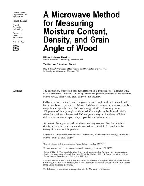
United StatesDepartment ofAgricultureForest ServiceForestProductsLaboratoryResearchNoteFPL-0250March 1985A <strong>Microwave</strong> <strong>Method</strong><strong>for</strong> <strong>Measuring</strong><strong>Moisture</strong> <strong>Content</strong>,<strong>Density</strong>, <strong>and</strong> GrainAngle of WoodWilliam L. James, PhysicistForest Products Laboratory, Madison, WIYou-Hsin Yen, 1Graduate StudentRay J. King, 2 Professor of Electronic <strong>and</strong> Computer Engineering,University of Wisconsin, Madison, WIAbstractThe attenuation, phase shift <strong>and</strong> depolarization of a polarized 4.81-gigahertz waveas it is transmitted through a wood specimen can provide estimates of the moisturecontent (MC), density, <strong>and</strong> grain angle of the specimen.Calibrations are empirical, <strong>and</strong> computations are complicated, with considerableinteraction between parameters. Measured dielectric parameters, however, correlateuniquely <strong>and</strong> repeatably with MC over a range of MC at least as great as100 percent of the dry weight of the wood. Grain angle can be deduced reliablywhen the specimen thickness <strong>and</strong> MC are great enough to introduce sufficientdielectric anisotropy to appreciably depolarize the incident wave.At present, the apparatus <strong>and</strong> techniques are very complex, but the principlesdeveloped by this research show the method to be feasible <strong>for</strong> nondestructivetesting of lumber as it is produced.Keywords: <strong>Microwave</strong> transmission, homodyne, nondestructive testing, moisturecontent, density, grain angle.1 Present address, Bell Communication Research, Inc., Homdel, NJ 07733.2 Present address, Lawrence-Livermore National Laboratory, Livermore, CA 94550.James, William L; Yen, You-Hsin; King, Ray J. A microwave method <strong>for</strong> measuring moisture content,density, <strong>and</strong> grain angle of wood. Res. Note FPL-0250. Madison, WI: U.S. Department of Agriculture,Forest Service, Forest Products Laboratory; 1985, 9 p.A limited number of free copies of this publication are available to the public from the Forest ProductsLaboratory, P.O. Box 5130, Madison, WI 53705. Laboratory publications are sent to over 1,000 librariesin the United States <strong>and</strong> elsewhere.The Laboratory is maintained in cooperation with the University of Wisconsin.
IntroductionA major difficulty in the use of wood in engineered structures is uncertainty in thedesign data <strong>for</strong> the individual load-bearing members. This difficulty would vanish ifeach member could be rated reliably as to its mechanical quality, through the use ofnondestructive tests. Because strength can be measured directly only throughdestructive testing, the basis <strong>for</strong> any nondestructive rating of strength is acorrelation between strength <strong>and</strong> other properties that can be measurednondestructively. Some properties that correlate in a generally useful way tostrength are density, moisture content (MC), <strong>and</strong> grain direction. This report gives abrief summary description of a microwave transmission method that shows promise<strong>for</strong> estimating rapidly <strong>and</strong> nondestructively these three factors <strong>for</strong> sawn lumber.These factors are essential if not sufficient <strong>for</strong> predicting with useful reliability thestrength of a given structural piece. The objective of the research reported here wasto develop the method <strong>and</strong> demonstrate its feasibility <strong>for</strong> in-line stress grading ofstructural lumber.Theoretical BasisThe dielectric properties of wood, which determine its characteristics intransmitting electromagnetic waves, are strongly dependent on MC <strong>and</strong> density ofthe wood. In addition, the dielectric properties are anisotropic, following thestructural anisotropy of the wood.The speed of propagation, <strong>and</strong> there<strong>for</strong>e the wavelength, of an electromagnetic waveis reduced when it travels through matter. This reduction in speed is in proportionto the dielectric constant of the matter, With wood, the dielectric constant dependson the density <strong>and</strong> MC of the wood. The retardation of the speed of propagation,there<strong>for</strong>e, is an indication of the density <strong>and</strong> MC of the specimen. The retardationis measurable as a phase change in the wave as it is transmitted through thespecimen.As it is transmitted through the specimen, the wave also suffers a loss of intensity,caused by absorption <strong>and</strong> scattering of the energy. The intensity loss depends on theloss factor <strong>and</strong> thickness of the specimen, <strong>and</strong> the loss factor of wood depends onits density <strong>and</strong> MC.Finally, when a linearly polarized wave enters the wood, the dielectric anisotropy ofthe wood causes the wave to become depolarized. The electric vector of the incidentwave is resolved into components in the directions of the maximum <strong>and</strong> theminimum dielectric constant. When the thickness <strong>and</strong> the degree of anisotropy ofthe specimen are sufficient, the wave emerging from the specimen is effectivelyelliptically polarized with its minor axis in the direction of the maximum dielectricconstant, which is essentially the direction of the grain. For lesser thickness oranisotropy, the polarization angle is less than the true grain angle by a factordefined as M, the depolarization index, in percent.This report, there<strong>for</strong>e, describes a method <strong>for</strong> measuring the attenuation, phasechange, <strong>and</strong> depolarization of a microwave beam as it passes through the specimen.These parameters interact extensively, so the data reduction is complicated. Butroughly, the attenuation reflects predominantly MC, phase change reflects bothmoisture <strong>and</strong> density, <strong>and</strong> details of the depolarization indicate grain angle.A complete description of the method was given by Yen (198 1).
Apparatus <strong>and</strong> <strong>Method</strong>sWe will give a very brief general description of the apparatus <strong>and</strong> methods.Essential details are available in the references (Ellerbruch 1965, King 1978; King<strong>and</strong> Yen 1981; Yen 1981).<strong>Microwave</strong> power at 4.81 gigahertz (GHz) is generated by a reflex klystron, <strong>and</strong>radiated from a linearly polarized horn antenna. The radiation passes through thespecimen essentially as a plane wave, <strong>and</strong> then is reflected back through thespecimen from a small dipole tuned to the 4.81-GHz frequency. The reflectingdipole also modulates the reflected wave, as explained below. The reflected energyreenters the same horn antenna from which it was radiated. The transmitted <strong>and</strong>reflected signals are combined in a homodyne circuit (termed “homodyne” becausethe reference signal (the transmitted wave) <strong>and</strong> the received signal (the reflectedwave) are of the same frequency).To produce sensible output from the homodyne detector, the reflected wave ismodulated in two ways simultaneously. First, the reflecting dipole is switched in<strong>and</strong> out of resonance at a lo-kilohertz (kHz) rate by means of a PIN diode at themidpoint of the dipole. The switching is done by cycling the diode betweenconducting <strong>and</strong> nonconducting states by a 10-kHz sine wave applied to it throughhigh resistance leads. When the diode is conducting, the dipole is a strong resonantreflector; when it is nonconducting, the dipole reflection is greatly reduced.Second, in addition to the 10-kHz amplitude modulation, a combined 300-Hzamplitude <strong>and</strong> phase-related modulation is produced by spinning the reflectingdipole at 9,000 revolutions per minute. A reference signal is derived from the shaftof the spinning dipole, which is compared to the phase of the 300-Hz modulation toindicate the polarization angle of the transmitted wave. The amplitude of the300-Hz modulation indicates the ratio of the major to minor axes of the ellipticallypolarized transmitted wave.The two signals, at the two modulation frequencies, derived from the homodynedetector are the actual data. From analysis of the amplitude <strong>and</strong> phase of thesesignals, <strong>and</strong> the specimen thickness, the two-dimensional dielectric tensor of thespecimen can be constructed using iterative methods. The relationships between theterms of the dielectric tensor <strong>and</strong> the desired physical properties of the wood areempirical, <strong>and</strong> must be established independently by measurements on wood ofknown properties.In making the measurements <strong>and</strong> computations, the incident wave is maintainednormal to the specimen surface, <strong>and</strong> reflections from the specimen are accounted<strong>for</strong> in the computation. Only two-dimensional anisotropy of the specimen isassumed. Varying slopes of grain were simulated by rotating specimens around anaxis through the microwave beam. The incident plane of polarization was eitherparallel or perpendicular to the grain, within ±20° or less.A block diagram of the apparatus is given (fig. 1) without extensive comment.Detailed explanation of figure 1 would not be useful here; it can be found in thereferences (King <strong>and</strong> Yen 1981; Yen 1981).3
Figure 1.—Block diagram of the microwave system. The arrow touching the output line from the 4.81-gigahertz generator (upper left) represents a section of slotted wave guide from which is obtained areference signal whose phase is adjusted by moving the probe in the slot. BPF = b<strong>and</strong> pass filter <strong>and</strong> LPF= low pass filter. Output data (right side): Θ = polarization angle, β = phase constant (phase shift indegrees per unit thickness). γ = depolarization ratio (ratio of minor to major axis of polarization ellipse),<strong>and</strong> α = attenuation constant (power loss in decibels per unit thickness). (ML84 5826)
Experimental ResultsSome preliminary measurements were made on a variety of specimens to determinehow well the system responds to the pertinent wood properties. Data givenrepresent the averages of several specimens <strong>and</strong> repeated measurements on each.Specimens used are described in table 1.The electrical parameters were repeatable with good precision when the one-waytransmission loss was no greater than about 20 decibels (power reduction by afactor of 100). The relationships between the electrical <strong>and</strong> physical parameters ofthe wood were similar <strong>for</strong> all specimens. Power loss <strong>and</strong> phase shift were essentiallyindependent of grain angle if grain angle deviated from the incident polarization byno more than ± 20° (Yen 1981). (This is a very important result, as it greatlysimplifies the data processing.) Power loss was predominantly affected by MC, thecorrelation being strongest when the incident polarization was nominally parallel tothe grain. The correlation between power loss per unit thickness, α, <strong>and</strong> MCappeared to remain strong <strong>and</strong> nearly linear even to MC levels greater than100 percent (fig. 2).The phase shift per unit thickness, β, depended on both density <strong>and</strong> MC of thespecimen (fig. 3), but the computations were able to infer density independent ofMC.When specimen thickness <strong>and</strong> MC were large enough, depending on the particularspecimen, the polarization angle of the transmitted beam was a good indicator ofthe grain angle (figs. 4-6). At lesser MC <strong>and</strong>/or thickness, the depolarization of theincident beam was not complete, <strong>and</strong> the effective transmitted polarization anglewas smaller than the grain angle by the factor M (fig. 4).The analysis of data obtained by the present method yielded the two-dimensionaldielectric tensor of the specimen (two instead of three dimensions because the radial<strong>and</strong> tangential directions were considered identical). For example, the dielectrictensors found <strong>for</strong> Douglas-fir at two different MC levels are as follows:6 PERCENT MC2.35 – j0.15 0.0018 + j0.00750.0027 + j0.01 1.9 – j0.09512 PERCENT MC2.73 – j0.7 0.0052 + j0.00780.0123 + j0.018 2.16 – j0.31The two diagonal elements of this 2 x 2 tensor are the complex dielectric constants inthe direction parallel to the grain <strong>and</strong> across the grain, respectively. The real (fig. 7)<strong>and</strong> imaginary (fig. 8) parts of these quantities are well correlated with MC over arange of MC extending to 100 percent or greater. The real part is the usual dielectricconstant, <strong>and</strong> the imaginary part is often called the loss factor. The loss tangent (ratioof imaginary to real parts-fig. 9) also correlates clearly with MC, but the relationshipis not as simple as that between MC <strong>and</strong> the real <strong>and</strong> imaginary parts separately.The off-diagonal elements of the dielectric tensor quantify interaction between theparallel- <strong>and</strong> across-grain constants. These elements appeared to be particularly sensitiveindicators of changes in MC (Yen 1981).5
Table 1.—Properties of specimen materialSpeciesWhite pineBasswoodAspenDouglas-firRed oakHickorySpecificgravity0.31-0.380.350.38-0.410.38-0.460.56-0.620.72-0.73<strong>Moisture</strong> content valuesThickness- - - - - - - - Pct ----------- Cm0, 6, 12, 204 1.5-5.080, 6, 12 1.80, 6, 12, 130 2.54-4.750, 6, 12, 31, 45, 52, 136, 150 0.7-5.080, 6, 12 1.8-4.10, 6, 12, 45, 48 2.4-4.5Table 2.—Comparison 1 of dielectric constants from present study with corresponding data obtained previously 2GraindirectionItemPresentstudy 3James<strong>and</strong>HamillParallelParallelPerpendicularPerpendicular6 PERCENT MOISTURE CONTENTDielectric constant 2.35Loss tangent 0.064Dielectric constant 1.9Loss tangent 0.05012 PERCENT MOISTURE CONTENT2.00.131.80.065Parallel Dielectric constant 2.73 2.85Parallel Loss tangent 0.26 0.22Perpendicular Dielectric constant 2.16 2.0Perpendicular Loss tangent 0.14 0.121 Previous data interpolated to same frequency as present study.2 Data obtained using a slotted line method (James <strong>and</strong> Hamill 1965).3 Data derived from dielectric tensors (table 2).The dielectric constant <strong>and</strong> loss tangent <strong>for</strong> Douglas-fir taken from the dielectric tensorobtained by the present method are compared here with corresponding values obtainedearlier (table 2) using a slotted line method (James <strong>and</strong> Hamill 1965). The agreementis good considering the differences in specimen material <strong>and</strong> experimental methods.For very wet <strong>and</strong>/or thick specimens, the transmission loss could be excessive. Forsuch specimens, the necessary data could be derived from a reflected rather than atransmitted beam (Kraszewski <strong>and</strong> Kulinski 1976).The depolarization appeared to be related to grain angle without significant confoundingfrom the growth rings (Yen 1981).The most persistent problem with this method, from a practical st<strong>and</strong>point, is spuriousreflection of microwave energy from the essential mechanical structures associatedwith the apparatus <strong>and</strong> specimen h<strong>and</strong>ling mechanism. Treatment of this problemincludes covering the structures with microwave absorbers, <strong>and</strong> adjusting the microwavesystem to minimize its sensitivity to reflected energy other than from the spinningdipole.
Figure 2.—Attenuation constant ofDouglas-fir parallel <strong>and</strong> perpendicular tothe grain as a function of moisture content.(ML84 5827)Figure 3.—Phase constant of Douglas-firparallel <strong>and</strong> perpendicular to the grain asa function of moisture content. (ML845828)Figure 4.—Depolarization index ofDouglas-fir as a function of specimenthickness <strong>and</strong> moisture content. Thenumbers at each curly are thecorresponding specimen thicknesses incentimeters. (ML84 5829)Figure 5.—Depolarization index percentimeter thickness of Douglas-fir as afunction of moisture content. (ML84 5832)7
Figure 6.—Relation between polarizationangle <strong>and</strong> grain angle <strong>for</strong> various speciesat various moisture content, <strong>for</strong> l-inchthickness. The slopes of these plots are thedepolarization index, M, expressed inpercent. WP = white pine, BS =basswood, AS = aspen, DF = Douglas-fir,RO = red oak, HI = hickory. Numbers inparentheses are moisture content. (ML845833)Figure 7.—Dielectric constant of Douglasfirparallel <strong>and</strong> perpendicular to the grainas a function of moisture content. (ML845830)Figure 8.—Loss factor of Douglas-jrparallel <strong>and</strong> perpendicular to the grain asFigure 9.—Loss tangent of Douglas-firparallel <strong>and</strong> perpendicular to the grain asa function of moisture content. (ML84a function of moisture content. (ML845831) 5834)8
Summary <strong>and</strong>ConclusionsThe research reported here demonstrates that a microwave transmission method,working at about 4.81 GHz <strong>and</strong> incorporating simultaneous amplitude <strong>and</strong> phasemodulation of the transmitted wave as it is reflected back to the transmitter, canprovide an accurate estimate of the dielectric tensor of the transmitting medium.With wood, the elements of the dielectric tensor, the polarization angle, <strong>and</strong>empirical calibration data can be used to infer the density, MC, <strong>and</strong> grain angle ofthe specimen. The correlations appear to be useful over a range of MC greater than100 percent. The computations are complicated, but a typical small computer canprovide the above quality parameters of the wood in real time (practicallyinstantaneously).The apparatus is also relatively complicated, but consists of components that arecommercially available or easily made in a typical machine shop. The cost of noneof the components is prohibitive; the complete system would probably cost about asmuch as a present-day production-line moisture meter. The power level of themicrowave beam is typically less than one watt, so poses no environmental hazard.This research shows that the microwave system described is potentially capable ofproviding production-line inspection of structural lumber, by recording density,MC, <strong>and</strong> grain direction of the material in real time. The size <strong>and</strong> physical layoutof the equipment would not be a problem in typical lumber mills, <strong>and</strong> thecomputer software <strong>for</strong> reducing the microwave data to the desired qualityparameters of the wood would be easily developed based on the results of thisresearch (King <strong>and</strong> Yen 1981; Yen 1981). Equipment <strong>for</strong> marking the individualboards according to the computer output is available.Literature Cited2•5-3185 U S GOVERNMENT PRINTING OFFICE: 1985—554–045–10025
The Forest ProductsLaboratory (USDA ForestService) has served as thenational center <strong>for</strong> woodutilization research since1910. The Laboratory, on theUniversity of Wisconsin-Madison campus, hasachieved worldwiderecognition <strong>for</strong> itscontribution to the knowledge<strong>and</strong> better use of wood.Early research at theLaboratory helped establishU.S. industries that producepulp <strong>and</strong> paper, lumber,structural beams, plywood,particleboard <strong>and</strong> woodfurniture, <strong>and</strong> other woodproducts. Studies now inprogress provide a basis <strong>for</strong>more effective management<strong>and</strong> use of our timberresource by answering criticalquestions on its basiccharacteristics <strong>and</strong> on itsconversion <strong>for</strong> use in a varietyof consumer applications.Unanswered questions remain<strong>and</strong> new ones will arisebecause of changes in thetimber resource <strong>and</strong>increased use of woodproducts. As we approach the21st Century, scientists at theForest Products Laboratorywill continue to meet thechallenge posed by thesequestions.