D01519/GB0 03-2006 Conventia Mounting Bases - Solar Danmark ...
D01519/GB0 03-2006 Conventia Mounting Bases - Solar Danmark ...
D01519/GB0 03-2006 Conventia Mounting Bases - Solar Danmark ...

Create successful ePaper yourself
Turn your PDF publications into a flip-book with our unique Google optimized e-Paper software.
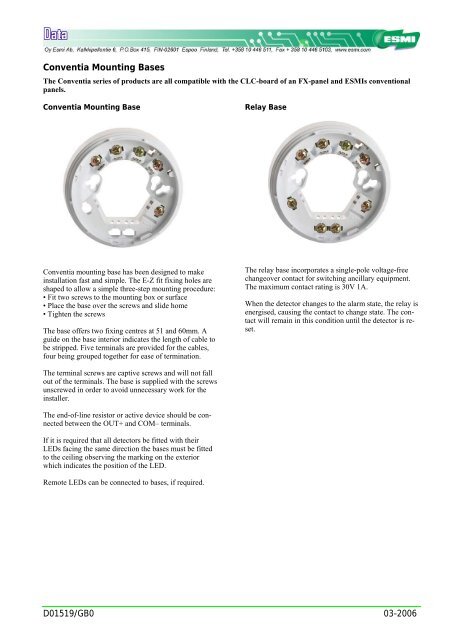
<strong>Conventia</strong> <strong>Mounting</strong> <strong>Bases</strong><br />
The <strong>Conventia</strong> series of products are all compatible with the CLC-board of an FX-panel and ESMIs conventional<br />
panels.<br />
<strong>Conventia</strong> <strong>Mounting</strong> Base<br />
Relay Base<br />
<strong>Conventia</strong> mounting base has been designed to make<br />
installation fast and simple. The E-Z fit fixing holes are<br />
shaped to allow a simple three-step mounting procedure:<br />
• Fit two screws to the mounting box or surface<br />
• Place the base over the screws and slide home<br />
• Tighten the screws<br />
The base offers two fixing centres at 51 and 60mm. A<br />
guide on the base interior indicates the length of cable to<br />
be stripped. Five terminals are provided for the cables,<br />
four being grouped together for ease of termination.<br />
The relay base incorporates a single-pole voltage-free<br />
changeover contact for switching ancillary equipment.<br />
The maximum contact rating is 30V 1A.<br />
When the detector changes to the alarm state, the relay is<br />
energised, causing the contact to change state. The contact<br />
will remain in this condition until the detector is reset.<br />
The terminal screws are captive screws and will not fall<br />
out of the terminals. The base is supplied with the screws<br />
unscrewed in order to avoid unnecessary work for the<br />
installer.<br />
The end-of-line resistor or active device should be connected<br />
between the OUT+ and COM– terminals.<br />
If it is required that all detectors be fitted with their<br />
LEDs facing the same direction the bases must be fitted<br />
to the ceiling observing the marking on the exterior<br />
which indicates the position of the LED.<br />
Remote LEDs can be connected to bases, if required.<br />
<strong>D01519</strong>/<strong>GB0</strong> <strong>03</strong>-<strong>2006</strong>
Technical data<br />
Base EBC-10 EBC-20<br />
Description Standard mounting base Relay base<br />
Operating voltage 8.5 – 33 VDC 8.5 – 33 VDC<br />
Current consumption N/A N/A<br />
Contact rating at 30V AC or DC N/C 1 A<br />
IP rating IP20 IP20<br />
Operating temperature -40ºC 70ºC<br />
Storage temperature -40ºC 70ºC<br />
Humidity (no condensation) 0-98% 0-98%<br />
Dimensions (∅ x h) 100 x 8 mm 100 x 8 mm<br />
Weight 60 60<br />
Esmi part number 0672 4010 0672 4020<br />
Detectors Optical smoke sensor EDC-20, 0672 4620<br />
Multisensor EDC-30, 0672 4621<br />
Heat detector EDC-50/A1R, 0672 4650<br />
Heat detector EDC-50/A2S, 0672 4652<br />
Heat detector EDC-50/BR, 0672 4640<br />
Heat detector EDC-50/BS, 0672 4641<br />
Heat detector EDC-50/CR, 0672 4646<br />
Heat detector EDC-50/CS, 0672 4647<br />
<strong>D01519</strong>/<strong>GB0</strong> 2 <strong>03</strong>-<strong>2006</strong>
1<br />
4<br />
1<br />
1<br />
4<br />
Schematic Diagram & Wiring Connections<br />
2 mounting bases and a relay base<br />
<strong>Mounting</strong> base<br />
RL<br />
LED -<br />
COM -<br />
IN+<br />
LED -<br />
Relay base<br />
COM -<br />
IN+<br />
OUT+<br />
OUT+<br />
Conventional<br />
loop<br />
_<br />
_<br />
2 3<br />
2 3<br />
<strong>Mounting</strong> base<br />
RL = Remote Led<br />
R = End of Line Resistor<br />
LED -<br />
COM -<br />
IN+<br />
OUT+<br />
Relay controlled device<br />
_<br />
R<br />
2 3<br />
4<br />
2 mounting bases wired with a common LED<br />
<strong>Mounting</strong> base<br />
<strong>Mounting</strong> base<br />
Conventional<br />
loop<br />
_<br />
RL<br />
LED -<br />
COM -<br />
IN+<br />
OUT+<br />
_<br />
LED -<br />
COM -<br />
IN+<br />
OUT+<br />
1<br />
4<br />
R<br />
2 3<br />
1<br />
4<br />
2 3<br />
Terminals<br />
<strong>Mounting</strong> base<br />
LED- Remote Led -<br />
Com-<br />
Loop in-<br />
Loop out -<br />
End of Line Resistor<br />
IN+ Loop in +<br />
OUT+ Loop out +<br />
1 Not Used<br />
2 Not Used<br />
3 Not Used<br />
4 Functional earth (screen)<br />
Relay base<br />
LED- Remote Led -<br />
Com-<br />
Loop in-<br />
Loop out -<br />
End of Line Resistor<br />
IN+ Loop in +<br />
OUT+ Loop out +<br />
1 Relay output Common<br />
2 Relay output NO (normally open)<br />
3 Relay output NC (normally closed)<br />
4 Functional earth (screen)<br />
DXXXXXXGB<br />
vk-vvvv