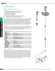
D A TA SHEET F110 - FLOW RA TE INDIC A ... - Bell Flow Systems
D A TA SHEET F110 - FLOW RA TE INDIC A ... - Bell Flow Systems
D A TA SHEET F110 - FLOW RA TE INDIC A ... - Bell Flow Systems

Create successful ePaper yourself
Turn your PDF publications into a flip-book with our unique Google optimized e-Paper software.
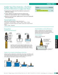
Configuration example IIB and IIC - <strong>F110</strong>-A-AF-(CT)-IB-OT-PD-XI - Power supply 16 - 30V DC<br />
<strong>TE</strong>RMINAL CONNECTORS<br />
F100-series<br />
HAZARDOUS AREA<br />
SAFE AREA<br />
TXD<br />
RXD<br />
DTR<br />
+12V<br />
Common ground<br />
26 27 28 29<br />
Modbus communication type CT: TTL<br />
Please note: communciation type CT is not allowed in IIC applications.<br />
+<br />
-<br />
Uo=max 30V<br />
Io=max 250mA<br />
Po=max 850mW<br />
ISOLATOR:<br />
I.S. Certified Isolator<br />
TTL to<br />
RS232 / RS422 / TTL<br />
For example: MTL5051<br />
<br />
e.g. PC<br />
+ 3.2V 1M<br />
low-pass<br />
filter<br />
Common ground<br />
Circuit depends on<br />
type of signal<br />
Supply *<br />
Signal<br />
Common ground<br />
12 13<br />
7 8 9 10 11<br />
Ci is negligibly<br />
small<br />
Ci is negligibly<br />
small<br />
Ci = 17nF<br />
Status input type IB:<br />
reset total<br />
<strong>Flow</strong>meter input type: A<br />
(0)4 - 20mA<br />
Analog output type AF:<br />
passive floating 4 - 20mA<br />
TO<strong>TA</strong>L Co OF ALL CONNEC<strong>TE</strong>D<br />
ANALOG APPA<strong>RA</strong>TUS IN IIC<br />
APPLICATIONS MAY NOT<br />
EXCEED 66nF MINUS 17nF<br />
(17nF IS USED BY THE ANALOG<br />
OUTPUT SIGNAL <strong>TE</strong>RMINAL 7 + 8).<br />
e.g. indicator<br />
Common ground<br />
5 6<br />
Ci is negligibly<br />
small<br />
Pulse output type OT:<br />
passive transistor<br />
123456<br />
e.g. counter<br />
+<br />
-<br />
Uo=max 30V<br />
Io=max 100mA<br />
Po=max 750mW<br />
POWER SUPPLY<br />
e.g. MTL 5025<br />
or<br />
SWITCH IN<strong>TE</strong>RFACE<br />
e.g. MTL 5011B<br />
123456<br />
e.g. counter<br />
0 1 2<br />
Uo=max 30V POWER SUPPLY<br />
Main supply<br />
Power supply type PD: 16 - 30V DC<br />
Io=max 100mA<br />
(please note: PD and battery supply (type PC) is NOT allowed in IIC applications).<br />
For example<br />
Common ground<br />
Po=max 750mW MTL5025<br />
Note: above values are safety values.<br />
Consult the technical specification for operational values.<br />
* Note power supply type PD: the supply voltage to pulse sensors is maximum 8.7V (Uo=max 8.7V Io=max 25mA Po=max 150mW) and to analog sensors as connected to terminal 1 (internally linked).<br />
+<br />
-<br />
8<br />
<strong>F110</strong>