KDF & KDG Micro FlowMeter and Switch - CA Briggs
KDF & KDG Micro FlowMeter and Switch - CA Briggs
KDF & KDG Micro FlowMeter and Switch - CA Briggs

Create successful ePaper yourself
Turn your PDF publications into a flip-book with our unique Google optimized e-Paper software.
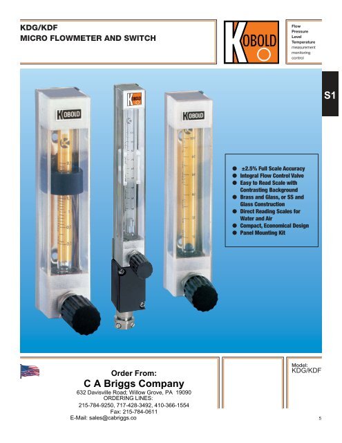
<strong>KDG</strong>/<strong>KDF</strong><br />
MICRO FLOWMETER AND SWITCH<br />
Flow<br />
Pressure<br />
Level<br />
Temperature<br />
measurement<br />
monitoring<br />
control<br />
S1<br />
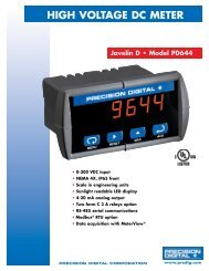
● ±2.5% Full Scale Accuracy<br />
● Integral Flow Control Valve<br />
● Easy to Read Scale with<br />
Contrasting Background<br />
● Brass <strong>and</strong> Glass, or SS <strong>and</strong><br />
Glass Construction<br />
● Direct Reading Scales for<br />
Water <strong>and</strong> Air<br />
● Compact, Economical Design<br />
● Panel Mounting Kit<br />
Order From:<br />
C A <strong>Briggs</strong> Company<br />
632 Davisville Road; Willow Grove, PA 19090<br />
ORDERING LINES:<br />
215-784-9250, 717-428-3492, 410-366-1554<br />
Fax: 215-784-0611<br />
E-Mail: sales@cabriggs.co<br />
Model:<br />
<strong>KDG</strong>/<strong>KDF</strong><br />
5
<strong>KDG</strong>/<strong>KDF</strong> - <strong>Micro</strong> flowmeter <strong>and</strong> switch<br />
Features<br />
●<br />
●<br />
●<br />
●<br />
●<br />
●<br />
●<br />
±2.5% Full Scale Accuracy<br />
Integral Flow Control Valve<br />
Easy to Read Scale with<br />
Contrasting Background<br />
Brass <strong>and</strong> Glass, or SS <strong>and</strong><br />
Glass Construction<br />
Direct Reading Scales for<br />
Water <strong>and</strong> Air<br />
Compact, Economical Design<br />
Panel Mounting Kit Optional<br />
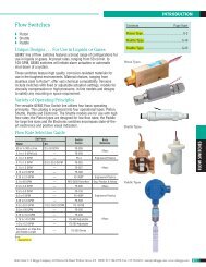
The <strong>KDG</strong>/<strong>KDF</strong> micro flowmeters operate on<br />
the float principle <strong>and</strong> are designed to<br />
measure low gas <strong>and</strong> liquid flows. Flow can<br />
be set exactly within the measuring range<br />
using the integral precision metering valve.<br />
The contrasting color background of the<br />
scale permits accurate data readings.<br />
Additionally, 1 or 2 adjustable switches may<br />
be mounted to identify certain flow<br />
conditions. A panel mounting kit is<br />
available as an option.<br />
Options<br />
1. Limit <strong>Switch</strong>es<br />
All meter ranges which have a stainless<br />
steel float can be fitted with optional,<br />
adjustable switches. Two types are<br />
available:<br />
Monostable: <strong>Switch</strong> activates momentarily<br />
as the stainless steel float passes by on<br />
rising flow.<br />
Bistable: <strong>Switch</strong> stays activated until the<br />
float falls past the switch on decreasing<br />
flow.<br />
<strong>Switch</strong> Specifications<br />
Output Type: NAMUR per DIN 19234<br />
(use EX-3001 or<br />
EX-3002 as isolation<br />
relay, sold separately)<br />
2. Junction Box<br />
A junction box is available for flowmeters<br />
with switches. The Junction-box contains<br />
a terminal block to facilitate making wiring<br />
connections. Flowmeters with switches<br />
which do not have a junction box will have<br />
wiring connections made via wire-leads<br />
fed through the bottom of the meter body.<br />
3. Constant Flow Controllers<br />
Two types of constant flow controllers are<br />
available. Types RE <strong>and</strong> NRE upstream<br />
pressure controllers. They hold flowrate<br />
constant when there is a varying<br />
downstream pressure <strong>and</strong> constant<br />
upstream pressure. All regulators are<br />
available in nickel-plated steel or brass.<br />
4. Panel Mounting Kit<br />
All flowmeters are available with an<br />
attached panel mounting plate <strong>and</strong><br />
mounting hardware. The mounting plate is<br />
made of anodized Aluminum. The panel<br />
cut-out required to accommodate the<br />
panel mounting plate is 3.15” x 1.57”<br />
(80mm X 40 mm).<br />
5. Custom Scales<br />
Custom, direct reading scales are available<br />
for the <strong>KDG</strong> <strong>and</strong> <strong>KDF</strong> series. The custom<br />
scales allow for a direct reading, calibrated<br />
for specific gravity, viscosity operating<br />
pressure or temperature. Any desired<br />
measuring units are possible.<br />
Specifications<br />
Accuracy: ±2.5% full scale<br />
Repeatability: ±0.6% full scale<br />
Connection: NPT 1 /4<br />
Mounting position: Vertically, media flow<br />
from bottom to top.<br />
Max. Pressure<br />
Brass or SS Fitting: 145 PSIG<br />
PVDF Fitting: 85 PSIG<br />
Max. Temperature: 210°F<br />
Fittings: brass, 316-Ti SS, or PVDF<br />
Measuring cone: Borosilicate glass with<br />
yellow background<br />
Float stop: PVDF<br />
Gaskets: Viton, or Chemraz<br />
Valve: 316-Ti SS<br />
Contact: (optional) bistable or<br />
monostable proximity switch for units with<br />
SS floats.<br />
6 Subject to change without prior notice.
<strong>KDG</strong>/<strong>KDF</strong> - <strong>Micro</strong> flowmeter <strong>and</strong> switch<br />
Liquids<br />
Order Details (Example: <strong>KDF</strong>-117NV0M2)<br />
Range Order no. Order no. Order no. Connection Gasket Panel <strong>Switch</strong> option<br />
l/h water brass stainless steel PVDF option mount kit<br />
0.25-2.5 <strong>KDF</strong>-1117... <strong>KDF</strong>-1217... <strong>KDF</strong>-1317... N=1/4 NPT V=Viton 0=without 00=without switch<br />
R=1/4 BSP T=FFKM S=with for model <strong>KDF</strong>-xx17<br />
0.5-5 <strong>KDF</strong>-1120... <strong>KDF</strong>-1220... <strong>KDF</strong>-1320... (Chemraz) without junction box<br />
M1=1 monostable switch<br />
1.2-12 <strong>KDF</strong>-1125... <strong>KDF</strong>-1225... <strong>KDF</strong>-1325... M2=2 monostable switches<br />
with junction box<br />
2.5-25 <strong>KDF</strong>-1128... <strong>KDF</strong>-1228... <strong>KDF</strong>-1328... A1=1 monostable switch<br />
A2=2 monostable switches<br />
4-40 <strong>KDF</strong>-1130... <strong>KDF</strong>-1230... <strong>KDF</strong>-1330... B1=1 bistable switch<br />
B2=2 bistable switches<br />
6-60 <strong>KDF</strong>-1135... <strong>KDF</strong>-1235... <strong>KDF</strong>-1335... for all other models<br />
without junction box<br />
10-100 <strong>KDF</strong>-1139... <strong>KDF</strong>-1239... <strong>KDF</strong>-1339... M3=1 monostable switch<br />
M4=2 monostable switches<br />
12-120 <strong>KDF</strong>-1140... <strong>KDF</strong>-1240... <strong>KDF</strong>-1340... with junction box<br />
A3=1 monostable switch<br />
16-160 <strong>KDF</strong>-1142... <strong>KDF</strong>-1242... <strong>KDF</strong>-1342... A4=2 monostable switches<br />
B3=1 bistable switch<br />
other liquids <strong>KDF</strong>-11YY... <strong>KDF</strong>-12YY... <strong>KDF</strong>-13YY... B4=2 bistable switches<br />
S1<br />
Gases<br />
Order Details (Example: <strong>KDG</strong>-1107NV0M2)<br />
Range Order no. Order no. Order no. Connection Gasket Panel <strong>Switch</strong> option<br />
l/h air brass stainless steel PVDF option mount kit<br />
0.5-5 <strong>KDG</strong>-1107... <strong>KDG</strong>-1207... <strong>KDG</strong>-1307... N=1/4 NPT V=Viton 0=without 00=without switch<br />
0.8-8 <strong>KDG</strong>-1109... <strong>KDG</strong>-1209... <strong>KDG</strong>-1309... R=1/4 BSP T=FFKM S=with up to model <strong>KDG</strong>-xx24<br />
1.6-16 <strong>KDG</strong>-1113... <strong>KDG</strong>-1213... <strong>KDG</strong>-1313... (Chemraz) without junction box<br />
4-40 <strong>KDG</strong>-1120... <strong>KDG</strong>-1220... <strong>KDG</strong>-1320... M1=1 monostable switch<br />
6-60 <strong>KDG</strong>-1124... <strong>KDG</strong>-1224... <strong>KDG</strong>-1324... M2=2 monostable switches<br />
10-100 <strong>KDG</strong>-1128... <strong>KDG</strong>-1228... <strong>KDG</strong>-1328... with junction box<br />
25-250 <strong>KDG</strong>-1132... <strong>KDG</strong>-1232... <strong>KDG</strong>-1332... A1=1 monostable switch<br />
50-500 <strong>KDG</strong>-1137... <strong>KDG</strong>-1237... <strong>KDG</strong>-1337... A2=2 monostable switches<br />
80-800 <strong>KDG</strong>-1142... <strong>KDG</strong>-1242... <strong>KDG</strong>-1342... B1=1 bistable switch<br />
100-1000 <strong>KDG</strong>-1146... <strong>KDG</strong>-1246... <strong>KDG</strong>-1346... B2=2 bistable switches<br />
180-1800 <strong>KDG</strong>-1151... <strong>KDG</strong>-1251... <strong>KDG</strong>-1351... from model <strong>KDG</strong>-xx28<br />
240-2400 <strong>KDG</strong>-1157... <strong>KDG</strong>-1257... <strong>KDG</strong>-1357... without junction box<br />
300-3000 <strong>KDG</strong>-1161... <strong>KDG</strong>-1261... <strong>KDG</strong>-1361... M3=1 monostable switch<br />
350-3500 <strong>KDG</strong>-1162... <strong>KDG</strong>-1262... <strong>KDG</strong>-1362... M4=2 monostable switches<br />
430-4300 <strong>KDG</strong>-1165... <strong>KDG</strong>-1265... <strong>KDG</strong>-1365... with junction box<br />
Other gases <strong>KDG</strong>-11YY... <strong>KDG</strong>-12YY... <strong>KDG</strong>-13YY... A3=1 monostable switch<br />
A4=2 monostable switches<br />
B3=1 bistable switch<br />
B4=2 bistable switches<br />
Subject to change without prior notice. 7
<strong>KDG</strong>/<strong>KDF</strong> - <strong>Micro</strong> flowmeter <strong>and</strong> switch<br />
Dimensions<br />
Bi-stable <strong>Switch</strong> Operation<br />
Contacts are bistable ring initiators, with 2<br />
initiators located one above the other in one<br />
housing. This pairing permits identification<br />
of the direction of movement of the float.<br />
The ring initiator thus provides bistable<br />
switch function based on the position of the<br />
float, whether above or below the initiator<br />
block. The direction of action can be<br />
reversed by turning the ring initiators around<br />
(change over top <strong>and</strong> bottom). One<br />
transistor relay (order no. Ex 3011) is<br />
required for each circuit (double version not<br />
available).<br />
Connection diagram<br />
EX 1011<br />
EX 3011<br />
1 Ring initiator 2 Ring initiator<br />
4 Power supply 5 Relay outputs<br />
Constant Flow Regulators<br />
Model Number Material Max. flow rate Min. required<br />
Water** Air** upstream pressure p1<br />
Upstream pressure controller l/h l/h p1 in PSI<br />
RE-1000-R stainless steel 40 1000 0.5<br />
RE-1000-N brass 40 1000 0.5<br />
RE-4000-R stainless steel 100 3400 1<br />
RE-4000-N brass 100 3400 1<br />
NRE-800-R stainless steel 800 0.2<br />
NRE-800-N brass 800 0.2<br />
Downstream pressure controller Air** Min. differential pressure *<br />
l/h<br />
p in PSI<br />
RA-1000-R stainless steel 1000 0.4<br />
RA-1000-N brass 1000 0.4<br />
RA-4000-R stainless steel 3400 0.8<br />
RA-4000-N brass 3400 0.8<br />
NRA-800-R stainless steel 800 0.15<br />
NRA-800-N brass 800 0.15<br />
*Pressure difference between upstream <strong>and</strong> downstream pressure<br />
**Reference conditions 68˚F, 14.7 PSIA<br />
8 Subject to change without prior notice.