RF Mixers
RF Mixers
RF Mixers

You also want an ePaper? Increase the reach of your titles
YUMPU automatically turns print PDFs into web optimized ePapers that Google loves.
<strong>RF</strong> <strong>Mixers</strong><br />
Iulian Rosu, YO3DAC / VA3IUL, http://www.qsl.net/va3iul<br />
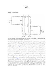
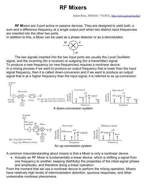
<strong>RF</strong> <strong>Mixers</strong> are 3-port active or passive devices. They are designed to yield both, a<br />
sum and a difference frequency at a single output port when two distinct input frequencies<br />
are inserted into the other two ports.<br />
In addition to this, a Mixer can be used as a phase detector or as a demodulator.<br />
The two signals inserted into the two input ports are usually the Local Oscillator<br />
signal, and the incoming (for a receiver) or outgoing (for a transmitter) signal.<br />
To produce a new frequency (or new frequencies) requires a nonlinear device.<br />
In a mixing process if we want to produce an output frequency that is lower than the input<br />
signal frequency, then it is called down-conversion and if we want to produce an output<br />
signal that is at a higher frequency than the input signal, it is referred to as up-conversion.<br />
A down-conversion system<br />
An up-conversion system<br />
A common misunderstanding about mixers is that a Mixer is only a nonlinear device.<br />
• Actually an <strong>RF</strong> Mixer is fundamentally a linear device, which is shifting a signal from<br />
one frequency to another, keeping (faithfully) the properties of the initial signal (phase<br />
and amplitude), and therefore doing a linear operation.<br />
From the moment that we use a nonlinear device to perform the mixing operation, <strong>Mixers</strong><br />
have relatively high levels of intermodulation distortion, spurious responses, and other<br />
undesirable nonlinear phenomena.
• In contrast to frequency multipliers and dividers, which also change signal frequency,<br />
<strong>Mixers</strong> theoretically preserve the amplitude and phase without affecting modulation<br />
properties of the signals at its ports.<br />
Important Mixer properties are:<br />
Conversion Gain or Loss, Intercept point, Isolation, Noise Figure, High-order spurious<br />
response rejection and Image noise suppression.<br />
1. Conversion Gain or Loss of the <strong>RF</strong> Mixer is dependent by the type of the mixer (active<br />
or passive), but is also dependent by the load of the input <strong>RF</strong> circuit as well the output<br />
impedance at the <strong>RF</strong> port. Also is dependent by the level of the LO.<br />
The typical conversion gain of an active Mixer is approximately +10dB when the conversion<br />
loss of a typical diode mixer is approximately -6dB.<br />
The Conversion Gain or Loss of the <strong>RF</strong> Mixer measured in dB is given by:<br />
Conversion [dB] = Output IF power delivered to the load [dBm] – Available <strong>RF</strong> input signal<br />
power [dBm]<br />
2. Input Intercept Point (IIP3) is the <strong>RF</strong> input power at which the output power levels of<br />
the unwanted intermodulation products and the desired IF output would be equal.<br />
• From an <strong>RF</strong> System point of view, a Mixer linearity is more critical than Noise Figure.<br />
The Third-Order intercept point (IP3) in a Mixer is defined by the extrapolated intersection<br />
of the primary IF response with the two-tone third-order intermodulation IF product that<br />
results when two <strong>RF</strong> signals are applied to the <strong>RF</strong> port of the Mixer.<br />
3. Spurious products in a Mixer are problematic, and Mixer vendors frequently provide<br />
tables showing the relative amplitudes of each response under given LO drive conditions.<br />
One way to reduce such products is to short-circuit the higher harmonics of the LO at the<br />
intrinsic Mixer terminals to lower the power in such responses.<br />
Reducing the second or third harmonic of the local oscillator reduces its harmonic products<br />
by 20 to 25 dB and 10 to 15 dB, respectively.
4. Isolation is the amount of local oscillator power that leaks into either the IF or the <strong>RF</strong><br />
ports. There are multiple types of isolation: LO-to-<strong>RF</strong>, LO-to-IF and <strong>RF</strong>-to-IF isolation.<br />
5. Noise Figure is a measure of the noise added by the Mixer itself, noise as it gets<br />
converted to the IF output.<br />
• For a passive Mixer which has no gain and only loss, the Noise Figure is almost<br />
equal with the loss.<br />
• In a mixer noise is replicated and translated by each harmonic of the LO that is<br />
referred to as Noise Folding.<br />
In addition to the degradation in system Noise Figure introduced by the conversion loss<br />
of the Mixer, noise sources within the Mixer device itself further corrupt the Noise Figure.<br />
For example, the effect of 1/f noise in MESFETs can be severe if the IF frequency is below<br />
the corner frequency of the flicker noise (normally less than 1 MHz), as this noise will add<br />
to the output.<br />
• A Mixer will convert energy in the upper or lower sidebands with equal efficiency.<br />
Consequently the noise in the side band with no signal will be added to the IF output,<br />
which will increase the Noise Figure at the IF port by 3dB, no matter how good the<br />
preceding component noise figure is. An Image Filter at the <strong>RF</strong> input of the Mixer<br />
could suppress this noise.<br />
Also there are some particular Image Reject mixers that suppress the image noise by their<br />
topology.<br />
The wideband noise of the Local Oscillator is another parameter that can raise the IF noise<br />
level, degrading in this way the overall Noise Figure. So, the wideband noise separated<br />
from the LO frequency by +/- f IF spacing will mix to produce noise at IF frequency.<br />
• Any noise that is near a multiple of the LO frequency can also be mixed down to the<br />
IF, just like the noise at the <strong>RF</strong>.<br />
This noise conversion process is related, but not the same as, the LO-to-<strong>RF</strong> isolation.<br />
• Noise at frequencies of +/- f IF spacing from the LO harmonics also contributes to<br />
overall system Noise Figure.<br />
• Wideband LO noise is down-converted to IF with much higher conversion loss than<br />
the desired signal and image noise.
• A Band Pass Filter between LO and the Mixer could help reducing the wideband LO<br />
noise.<br />
• In case of <strong>Mixers</strong>, the Noise Figure is defined for both the image and <strong>RF</strong> responses,<br />
and the output noise is generated by the input termination includes only the noise<br />
arising from the principal frequency transformation of the system.<br />
When a Single Sideband Noise Figure at the <strong>RF</strong> input is to be determined, the output<br />
noise arising from the input termination, at the image frequency is not included.<br />
Furthermore, it is impossible to measure directly the noise figure thus defined, because<br />
noiseless image terminations are difficult to obtain. The use of a filter to eliminate the image<br />
response (only to do accurate NF measurement) does not help because it changes the<br />
image-frequency embedding impedance, and hence changes the noise temperature. So,<br />
an alternate definition of SSB Noise Figure has found more common use.<br />
When a noisy LO signal is applied to the Mixer, its noise components at the <strong>RF</strong> and<br />
image frequencies are down converted and appear at the IF port, just as if they had been<br />
applied to the <strong>RF</strong> input. It is important to pick the IF frequency high enough so that noise at<br />
the <strong>RF</strong> and image frequencies are well separated from the LO and can be filtered<br />
effectively.<br />
• SSB NF assumes signal input from only one sideband, but noise inputs from both<br />
sidebands. Measuring SSB noise figure is relevant for Superheterodine receiver<br />
architectures in which the image frequency is removed by filtering or cancellation.<br />
• DSB NF includes both signal and noise inputs from both sidebands. A DSB NF is<br />
easier to measure; wideband excess noise is introduced at both the signal and image<br />
frequencies. It will be 3 dB less than the SSB noise figure in most cases.<br />
This is perhaps more relevant for Direct Conversion receivers where the image<br />
cannot be filtered out from the signal.<br />
<strong>Mixers</strong> can be divided into several classes:<br />
1. Single-device Mixer<br />
2. Single Balanced Mixer<br />
3. Double Balanced Mixer.<br />
1. Single-device Mixer which is using one nonlinear component (one diode, or one<br />
transistor) has the disadvantage of not attenuating local oscillator AM noise and<br />
always requires an injection filter.<br />
Single-device mixers need to follow some general design rules for best performance.<br />
• To get the maximum conversion gain the LO node should be a short circuit at the <strong>RF</strong><br />
and IF frequencies, while the <strong>RF</strong> node should be a short circuit at the LO frequency to<br />
prevent the LO leakage into the <strong>RF</strong> port.<br />
Single-device Mixer using one diode is primarily a process of matching the pumped<br />
diode to the <strong>RF</strong> input and IF output, terminating the diode properly at LO harmonics and<br />
unwanted mixing frequencies (other than the <strong>RF</strong> and IF), and isolating the <strong>RF</strong>, LO, and IF<br />
ports. That isolation, and in some cases the termination, can be provided by using filters, a<br />
balanced structure, or both. The choice depends on the frequency range and the intended<br />
application.
The diode used for mixing can be modeled at the <strong>RF</strong> frequency as a resistor and capacitor<br />
in parallel. The resistor is usually in a range of 50 to 150 ohms and the capacitor between 1<br />
and 1.5 times the junction capacitance. The IF output impedance is usually between 75<br />
ohms and 150 ohms. At low IF frequencies the output impedance is almost pure resistive.<br />
As the LO level increases, both <strong>RF</strong> and the LO input impedances decrease.<br />
The <strong>RF</strong> and IF input impedances mentioned above (high or low end on the range) are<br />
affected by the IF port termination on unwanted and LO harmonics frequencies. The<br />
diode’s termination at the image frequency is the most critical of all the terminations at<br />
unwanted mixing frequencies.<br />
• Terminating the IF port in a reactance at image frequency can improve the<br />
conversion efficiency of the Mixer.<br />
For selecting the mixing diode have to look for the cut-off frequency of the diode, for series<br />
resistance Rs and junction capacitance Cj. Minimizing both Rs and Cj is necesarly to<br />
achieve low conversion loss and distortion, but they are inverse trade-offs.<br />
• Sometimes it helps to apply a DC bias to a single-diode mixer which can reduce the<br />
required LO power and provides a degree of freedom for adjusting the mixer’s input<br />
and output impedances.<br />
In active Single-device design case (i.e. one-transistor Mixer), to prevent oscillations the IF<br />
node should be a short circuit at both LO and <strong>RF</strong> frequencies, and <strong>RF</strong> should be low<br />
impedance at IF frequency. This also prevent that the noise at the IF frequency is not<br />
amplified and added to the output.<br />
Single-device <strong>Mixers</strong> using FETs (two approaches for LO input)
The input filters, which are necessary to achieve <strong>RF</strong>-to-LO isolation and prevent<br />
radiation of the LO back through the antenna or other <strong>RF</strong> input, should attempt to shortcircuit<br />
all unwanted frequencies (i.e., those other than the <strong>RF</strong>-and-LO) so there are no<br />
interfering voltages appearing at the input.<br />
The input should be matched to the <strong>RF</strong> to maximize conversion gain and noise figure,<br />
and if possible, to the LO as well for LO power transfer. The image frequency should be<br />
short-circuited (if possible), as well as the IF, so neither noise nor spurious signals are<br />
amplified by the device. It is important that the device not behave as an amplifier at the IF,<br />
especially if the IF is low where the device gain is high.<br />
• As a general rule in active Mixer design, all undesired frequencies should be shortcircuited<br />
at both the input and the output to minimize distortion, noise, and for<br />
stability.<br />
• The IF port impedance at IF frequency should be relative high for best conversion<br />
gain, but in this way decreasing the IM distortion performance.<br />
• The IF port should provide enough rejection of the LO frequency in order to do not<br />
overload any further IF amplifiers down the chain.<br />
• FET mixers, especially single-gate FET mixers with LO and <strong>RF</strong> applied to the gate,<br />
have more serious LO-to-<strong>RF</strong> isolation problem because the LO signal is amplified by<br />
the FET.<br />
Single-device <strong>Mixers</strong> using one Diode<br />
A dual-gate MOSFET will give much improvement for LO-to-<strong>RF</strong> isolation (approximately<br />
20dB).<br />
Dual-gate MOSFET Mixer
2. Balanced <strong>Mixers</strong> are grossly divided into two classes, called Singly-Balanced <strong>Mixers</strong><br />
(SBM) and Doubly-Balanced <strong>Mixers</strong> (DBM).<br />
- Singly-Balanced mixers use two devices, and are usually realized as two singledevice<br />
mixers connected via a 180-degree or 90-degree hybrid.<br />
Double balanced mixers usually consist of four un-tuned devices interconnected by multiple<br />
hybrids, transformers or baluns.<br />
The advantages of balanced mixers over single-device mixers are:<br />
- Rejection of spurious responses and intermodulation products.<br />
- Better LO-to-<strong>RF</strong>, <strong>RF</strong>-to-IF and LO-to-IF isolation.<br />
- Rejection of AM noise in the LO<br />
The disadvantage of balanced mixers is their greater LO power requirements.<br />
Balanced mixers often used to separate the <strong>RF</strong> and LO ports when their frequency<br />
overlaps and filtering is impossible. In practice a perfect doubly balanced mixer give 10-<br />
30dB isolation without any filtering (depends by frequency and structure)<br />
A Singly-Balanced Mixer consists of two single-diode mixing elements, which may be two<br />
diodes or two transistors.<br />
In a singly-balanced diode Mixer it is essential that the DC path through the diodes to be<br />
continuous.<br />
If the diodes are open-circuited at DC, the Mixer it will not work. Often, the hybrid provides<br />
that path.<br />
In single-balanced using a quadrature hybrid the LO power reflected from the<br />
individual mixers does not return to the LO port, but instead exits the <strong>RF</strong> port; similarly,<br />
reflected <strong>RF</strong> power exits the LO port.<br />
The LO-to-<strong>RF</strong> and <strong>RF</strong>-to-LO isolation is therefore equal to the input return loss of the<br />
individual mixers at the LO and <strong>RF</strong> frequencies, respectively; the port isolation of the<br />
quadrature hybrid mixer depends primarily on the input VSWRs of the two individual<br />
mixers, not on the isolation of the hybrid itself. Isolation of 10dB is typical.<br />
If the <strong>RF</strong> port termination has a poor VSWR at the LO frequency, the circuit’s balance can<br />
be upset and the LO pumping of the individual mixers becomes unequal.<br />
The same, a poor LO port termination at the <strong>RF</strong> frequency can upset <strong>RF</strong> balance.<br />
The even LO harmonics rejection depends by which port is used for LO input (Sigma or<br />
Delta).
Whatever input is used for LO the mixer reject the even LO harmonics that mix with the<br />
even <strong>RF</strong> harmonics.<br />
• To reduce the overall Noise Figure of the Mixer the two diodes shall be well matched.<br />
Diodes can be matched on <strong>RF</strong> characteristics (conversion loss, IF impedance and<br />
VSWR), but are more easily matched on DC parameters (junction capacitance, series<br />
resistance and forward voltage) that can be measured readily for all diode outlines,<br />
including beam lead types.<br />
- Doubly-Balanced <strong>Mixers</strong> have higher conversion loss (or lower gain) than Singlybalanced<br />
<strong>Mixers</strong> and lower limit in maximum frequency, but has broader bandwidth.<br />
The two most common types of doubly balanced mixers are the Ring Mixer and the Star<br />
Mixer.<br />
The Ring Mixer is more suitable for low-frequency applications, in which transformers can<br />
be used, but it is also practical at high frequencies.<br />
Double-balanced <strong>Mixers</strong> (Diodes, BJTs, FETs)<br />
Ring Double-balanced <strong>Mixers</strong> can be described by treating its nonliniear components<br />
(diode or transistors) as switches, which are turned ON and OFF by the LO. This approach<br />
assumes that the conductance waveform of the diodes is a square wave, which is<br />
approximately true, as long as the LO level is great enough and its frequency is not too<br />
high.<br />
• In Double-balanced diode <strong>Mixers</strong> because of the symmetry, even-order spurious<br />
responses are also rejected.<br />
• Because the <strong>RF</strong> voltage is split between four diodes, the <strong>RF</strong> power in each diode is<br />
one-quarter that of a single-balanced mixer, so the 1-dB compression point and thirdorder<br />
intercept point are almost 6 dB higher.<br />
• However, four times as much LO power is now required to pump the diodes to the<br />
same degree.<br />
• The conversion loss is the same, because the <strong>RF</strong> power is split four ways and the IF<br />
power recombined four ways; therefore, the increase in intercept point provides a true<br />
increase in dynamic range due to the increase in output compared to a single diode.
Beyond about +10dBm LO power, the increase in intercept point does not rise as fast as<br />
the LO power, because the ON diodes begin to limit the LO voltage across the OFF diodes,<br />
which are in parallel. To each diode, the <strong>RF</strong> current is indistinguishable from the LO<br />
current, and the total <strong>RF</strong> swing is therefore limited in the OFF condition. This can be<br />
improved by using two or more diodes in series in place of the single diodes shown.<br />
• Many of the advantages of balanced structures, such as improved isolation, reduced<br />
spurious response, and improved intercept point, can be achieved for Active <strong>Mixers</strong> in<br />
the same way as for Diode <strong>Mixers</strong>.<br />
Symmetric or anti-symmetric pairing of identical basic mixers provides an effective means<br />
to attenuate some unwanted frequency components in the spectra of the input and output<br />
signals.<br />
The suppression is especially needed for the large local oscillator signal, which could<br />
saturate or seriously reduce the performances of an IF amplifier stage, but it is important for<br />
components with smaller amplitude also. Intermodulation within external systems of these<br />
unwanted components could mix with wanted signal and produce spurious signals that can<br />
interfere with other circuits of the system.<br />
• Double-balanced FET <strong>Mixers</strong> can be designed for both passive and active use.<br />
• Active FET <strong>Mixers</strong> based on Gilbert-cell architecture with biased semiconductor<br />
devices, can work with low LO levels and often provide conversion gain, but with<br />
decreased linearity compared to passive mixers.<br />
• Passive FET <strong>Mixers</strong>, usually based on FET quads, provide good linearity but require<br />
high LO levels and exhibit high conversion loss.<br />
The operation of this type of Mixer is similar to that of a conventional diode-based Doublebalanced<br />
Mixer. The main difference is that the FET Mixer has six terminals, compared to<br />
the four terminals of the Double-balanced diode Mixer.<br />
During the positive half-cycle of the LO signal to the FET mixer, two of the FETs are in<br />
conduction while the other two are turned off. As a result, the secondary winding of the <strong>RF</strong><br />
balun is connected to the secondary winding of the IF balun through the FETs that are<br />
switched on. During the LO signal’s negative half-cycle, the FETs which were on during the<br />
positive half-cycle are turned off and vice versa.
This results in a reversal of the polarity of the <strong>RF</strong> signal reaching the IF balun.<br />
The frequency at which the FETs are turned on and off is determined by the frequency<br />
of the LO signal. This is mathematically equivalent to a multiplication of the <strong>RF</strong> and LO<br />
signals, resulting in the generation of sum and difference frequencies at the IF port.<br />
Compared to diode mixers, FET mixers have better P1dB compression point performances.<br />
The linearity performance of a FET mixer, as evaluated in terms of the third-order<br />
intercept point, is affected by variations in the load impedance. Thus, the most predictable<br />
performance occurs with a purely resistance termination as the load. This type of stable<br />
termination can be achieved by terminating the mixer with a filter, but the filter appears<br />
purely resistive only within its 3-dB passband. As the filter's impedance rises beyond its<br />
passband, the mixer's intercept performance degrades.<br />
• In an active FET mixer, the devices are biased for gain, but at the expense of<br />
intercept-point performance.<br />
• Passive mixers require higher LO power levels, but provide better third-orderintercept<br />
performance.<br />
Image-Reject <strong>Mixers</strong><br />
The Image-rejection Mixer is realized as the interconnection of a pair of balanced<br />
<strong>Mixers</strong>. It is especially useful for applications where the image and <strong>RF</strong> bands overlap, or<br />
the image is too close to the <strong>RF</strong> to be rejected by a filter.<br />
The LO ports of the balanced mixers are driven in phase, but the signals applied to the <strong>RF</strong><br />
ports have 90 degrees phase difference. A 90-degrees IF hybrid is used to separate the <strong>RF</strong><br />
and image bands.<br />
• Image Rejection improves with higher LO.<br />
• Image rejection depends more strongly on phase mismatch.<br />
Single-Sideband (SSB) or In-Phase/Quadrature (I/Q) <strong>Mixers</strong><br />
SSB or I/Q modulators are useful in discriminating and removing the lower sideband (LSB)<br />
or upper sideband (USB) generated during frequency conversion, especially when<br />
sidebands are very close in frequency and attenuation of one of the sidebands cannot be<br />
achieved with filtering.<br />
• With an I/Q modulator, one of the sidebands is attenuated along with its carrier.
I/Q modulators basically consist of two Double-balanced <strong>Mixers</strong>. The <strong>Mixers</strong> are fed at the<br />
LO ports by a carrier phase-shifted with 90 degrees (0 degrees to one mixer and 90<br />
degrees to the other mixer). Modulation signals are fed externally in phase quadrature to<br />
the two mixers IF ports. The modulated mixers outputs are combined through a two-way inphase<br />
combiner.<br />
The circuit forms a phase cancellation network to one sidebands and a phase addition<br />
network to the other sideband. The carrier is also attenuated and is directly dependent on<br />
the LO-to-<strong>RF</strong> isolation of the two mixers.<br />
Phase and amplitude imbalance errors affect the side band suppression.<br />
• A diode Double-balanced Mixer can be used as a DC-controlled attenuator if PIN<br />
diodes are used instead of Shottky devices in its ring.<br />
Sub-harmonic <strong>Mixers</strong><br />
A Sub-harmonic Mixer has an LO input at frequency = LO/n. They are useful at higher<br />
frequencies when it can be difficult to produce a suitable LO signal (low phase noise, tuning<br />
range and output power all become more difficult to achieve with increasing frequency,<br />
whilst cost increases).<br />
• Sub-harmonic mixers us anti-parallel diode pairs.<br />
• These mixers produce most of their power at “odd” products of the input signals.<br />
• Even products are rejected due to the I-V characteristics of the diodes.<br />
• Attenuation of even harmonics is determined by diodes “balance”.<br />
• Diode “match” is critical.
• The short circuit λ LO /2 stub at the LO port is a quarter of a wavelength long at the<br />
input frequency of LO/2 and so is open circuit. However, at <strong>RF</strong> frequency this stub is<br />
approximately a half wavelength long, so providing a short circuit to the <strong>RF</strong> signal.<br />
• At the <strong>RF</strong> input the open circuit λ LO /2 stub presents a good open circuit to the <strong>RF</strong> but<br />
is a quarter wavelength long at the frequency LO/2 and so is short circuit.<br />
• The IF is normally far enough away from the <strong>RF</strong> frequency to allow easy realization of<br />
an IF filter presenting an open circuit output to the <strong>RF</strong> port.<br />
<strong>Mixers</strong> as Phase Detectors<br />
In a Double-balanced Mixer the output at the IF port contains the sum and difference of the<br />
frequencies of the signals input to the LO and <strong>RF</strong> ports.<br />
• If the <strong>RF</strong> and LO signals have identical frequencies, then their difference is zero Hz,<br />
or DC, which is the desired output for a phase detector. Their sum, which is twice the<br />
input frequency, can be selectively filtered out if it is not already beyond the frequency<br />
response of the IF port.<br />
The voltage at the IF port will be DC and will vary as the cosine of the phase difference<br />
between the LO and <strong>RF</strong> signals. Null readings for IF voltage are thus obtained whenever<br />
the phase difference between the LO and <strong>RF</strong> signals is equal to n*PI/2 with n = ±1, ±3, ...,<br />
while maximum and minimum readings are obtained for phase difference equal with n*PI<br />
where n = 0, ±1, ±2,…
Practical mixers that are used as phase detectors they often display some characteristics<br />
which differ from those of idealized mixers.<br />
The characteristics of most interest are DC offset and/or mixer-induced phase shift of the<br />
signals due to circuit imbalance. Parameters that affects these characteristics are:<br />
frequency, LO and <strong>RF</strong> drive levels, load resistance, and temperature.<br />
• The origin of DC offset voltages is a combination of diode imbalance and transformer<br />
asymmetry and can come from either or both input signals. In addition to isolation and<br />
LO drive level, DC offset is also affected by the load resistance and temperature.<br />
• Even after the effects of DC offset have been minimized, it is still possible that a null<br />
reading will be obtained at some relative phase other than PI/2 (90 degrees).<br />
This is because the mixer itself may change the relative phase of the two input<br />
signals due to the fact that the electrical length from the LO-to-IF port is not identical<br />
to that from the <strong>RF</strong>-to-IF port.<br />
• Frequency affects the DC offset by virtue of its effect upon isolation.<br />
• Higher the isolation between ports, lower the DC offset.<br />
• Also, as conversion loss decreases, maximum output DC voltage increases.<br />
References:<br />
1. <strong>RF</strong> Circuit Design for Wireless Applications – U. Rohde, D. Newkirk<br />
2. Microawave <strong>Mixers</strong> - Stephen Maas<br />
3. Nonlinear Microwave and <strong>RF</strong> Circuits - Stephen Maas<br />
4. <strong>RF</strong> Design Guide – P. Vizmuller<br />
5. <strong>RF</strong> Circuits Design - Theory and Applications - Ludwig, Bretchko<br />
6. Practical Rf Circuit Design for Modern Wireless Systems – R. Gilmore, L. Besser<br />
7. <strong>RF</strong> Circuit Design - W. Davis, Krishna Agarval<br />
8. Microwave Journal Magazine – 1997 - 2007