PS2 Morse code encoder (not PIC based)
PS2 Morse code encoder (not PIC based)
PS2 Morse code encoder (not PIC based)

You also want an ePaper? Increase the reach of your titles
YUMPU automatically turns print PDFs into web optimized ePapers that Google loves.
Application Note<br />
AN2xxx<br />
Easy <strong>Morse</strong> Coder<br />
Authors: S. G. Sriharsha<br />
H. N. Naveen<br />
Associated Project: Yes<br />
Associated Part Family: CY8C27xxx<br />
PSoC Designer Version: 4.1<br />
Associated Application Notes: AN2124, AN2xxx<br />
Abstract<br />
Amateur radio operators simply called as HAM radio operators use morse <strong>code</strong> for<br />
communicating with other radio operators. Although morse <strong>code</strong> is <strong>not</strong> being used extensively in<br />
modern day communication, it is used during emergency messaging and by amateur radio<br />
operators during contests and general two way contacts.<br />
This application <strong>not</strong>e explains how an amateur radio operator can generate <strong>Morse</strong> <strong>code</strong> easily<br />
using a standard computer PS/2 keyboard, a PSoC device and few external components. This<br />
document is an extension of the application <strong>not</strong>e AN2xxxx, “Interfacing PS/2 Keyboard using SPI<br />
Slave”.<br />
Introduction<br />
In 1836, Samuel <strong>Morse</strong> demonstrated the<br />
ability of a telegraph system to transmit<br />
information over wires. The information was<br />
sent as a series of electrical signals. Short<br />
signals are referred to as dits (represented<br />
as dots). Long signals are referred to as<br />
dahs (represented as dashes). With the<br />
advent of radio communications, an<br />
international version of <strong>Morse</strong> <strong>code</strong> became<br />
widely used.<br />
In amateur radio "<strong>code</strong>" generally refers to<br />
the International <strong>Morse</strong> Code. Adopted<br />
world wide in the early 1900's for all<br />
commercial international communication,<br />
amateurs too adopted its use.<br />
Since <strong>Morse</strong> relies on only an (on-off keyed)<br />
radio signal, it requires less complex<br />
equipment than other forms of radio<br />
communication, and it can be used in very<br />
high noise/low signal environments. It also<br />
requires less bandwidth than voice<br />
communications, typically 100-150 Hz.<br />
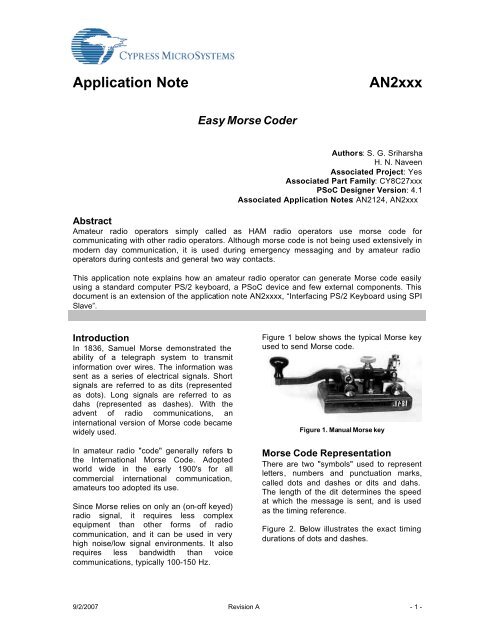
Figure 1 below shows the typical <strong>Morse</strong> key<br />
used to send <strong>Morse</strong> <strong>code</strong>.<br />
Figure 1. Manual <strong>Morse</strong> key<br />
<strong>Morse</strong> Code Representation<br />
There are two "symbols" used to represent<br />
letters, numbers and punctuation marks,<br />
called dots and dashes or dits and dahs.<br />
The length of the dit determines the speed<br />
at which the message is sent, and is used<br />
as the timing reference.<br />
Figure 2. Below illustrates the exact timing<br />
durations of dots and dashes.<br />
9/2/2007 Revision A - 1 -
3T<br />
DASH<br />
Figure 2. <strong>Morse</strong> <strong>code</strong> symbols<br />
In full-speed <strong>Morse</strong>, a dah is conventionally<br />
3 times as long as a dit shown in figure 2.<br />
Spacing between dits and dahs in a<br />
character is the length of one dit. Spacing<br />
between letters in a word is the length of a<br />
dah (3 dits). Spacing between words is 7<br />
dits.<br />
PSoC and PS/2 Keyboard<br />
In this example the PSoC device is<br />
interfaced with the PS/2 keyboard. An LCD<br />
is connected to the PSoC in-order to display<br />
the key presses. In this example, only the<br />
Device-to-Host mode of communication is<br />
shown.<br />
The PSoC device is configured for a SPI<br />
slave and a PWM8. The SPI slave is used<br />
for communicating with the keyboard and<br />
PWM8 is used for controlling the contrast of<br />
the LCD.<br />
For complete information on interfacing a<br />
PSoC and a PS/2 keyboard, please refer to<br />
the Cypress application <strong>not</strong>e “AN2XXX,<br />
Interfacing PS/2 Keyboard using SPI Slave”.<br />
T<br />
T<br />
DIT<br />
SPI Slave<br />
The SPIS User Module is a Serial Peripheral<br />
Interconnect Slave. It performs full duplex<br />
synchronous 8-bit data transfers. SCLK<br />
phase, SCLK polarity, and LSB First can be<br />
specified to accommodate most SPI<br />
protocols.<br />
The SPIS is used to communicate with the<br />
keyboard.<br />
PWM8<br />
PWM8 is an 8-bit pulse width modulator with<br />
programmable period and pulse width. The<br />
clock and enable can be selected from<br />
several sources.<br />
The PWM8 controls the LCD contrast.<br />
PWM16<br />
PWM16 is an 16-bit pulse width modulator<br />
with programmable period and pulse width.<br />
The clock and enable can be selected from<br />
several sources.<br />
The <strong>Morse</strong> <strong>code</strong> is generated using PWM16<br />
user module.<br />
LCD Tool box<br />
The LCD Tool Box User Module is a set of<br />
library routines that writes text strings and<br />
formatted numbers to a common two- or<br />
four-line LCD module.<br />
Port 1 of PSoC is used to drive the LCD in<br />
4-bit interface mode to limit the number of<br />
I/O pins required.<br />
The schematic of the easy <strong>Morse</strong> <strong>code</strong>r<br />
example is provided as Figure.5.<br />
PSOC User Modules<br />
The figure 3 shows the PSoC user module<br />
placement of the keyboard example.<br />
The following user modules are used in the<br />
easy <strong>Morse</strong> <strong>code</strong>r example:<br />
• SPI Slave<br />
• PWM8 - LCD Contrast<br />
• PWM16 - <strong>Morse</strong> Code Output<br />
• LCD Tool box<br />
9/2/2007 Revision A - 2 -
Figure 3. PSoC User Module Placement<br />
Algorithm:-<br />
Algorithm for the easy <strong>Morse</strong> <strong>code</strong>r project<br />
is given below:<br />
This has 2 functions<br />
• Key board<br />
• <strong>Morse</strong> transmission<br />
Keyboard<br />
1. Initialize all modules and set <strong>Morse</strong><br />
transmission speed default.<br />
2. Wait for any key stroke from key board.<br />
3. Recognize key.<br />
4. If it is Function keys, Set morse<br />
transmission speed or change contrast<br />
of LCD by changing the pulse width of<br />
PWM or Transmit <strong>Morse</strong> <strong>code</strong> if array<br />
has some character.<br />
5. Else if it is Character store it an array<br />
and display the same on LCD.<br />
6. Back to step 2.<br />
4. Check LSB is ‘0’ or ‘1’, If ‘0’ keep port<br />
2[3] high for ‘T’ sec. If ‘1’ than high for<br />
‘3T’ sec (Value of ‘T’ depends of speed<br />
setting).<br />
5. Right shift <strong>Morse</strong> <strong>code</strong> to transmit next<br />
bit, if any.<br />
6. Clear array and Display blank.<br />
7. Repeat steps from 1 to 5.<br />
Flow chart<br />
Figure 4 shows the flow chart of the easy<br />
<strong>Morse</strong> <strong>code</strong>r project.<br />
<strong>Morse</strong> Transmission<br />
1. Preferred key to transmit is Return key<br />
(Enter key).<br />
2. Disable keyboard and Enable Global<br />
interrupt.<br />
3. Get <strong>Morse</strong> <strong>code</strong> and No. of bits to<br />
transmit.<br />
9/2/2007 Revision A - 3 -
Initialize PSoC user<br />
modules<br />
Set morse speed<br />
Display on LCD<br />
NO<br />
Is any key<br />
pressed?<br />
YES<br />
Is Function<br />
Key pressed?<br />
YES<br />
NO<br />
De<strong>code</strong> key using<br />
look-up table<br />
Store in array<br />
F1 key<br />
pressed?<br />
NO<br />
YES<br />
Decrease LCD<br />
contrast control<br />
Display the aray<br />
contents on LCD<br />
F2 key<br />
pressed?<br />
NO<br />
YES<br />
Increase LCD<br />
contrast control<br />
ESC key<br />
pressed?<br />
YES<br />
Increase LCD<br />
contrast control<br />
NO<br />
Enter key<br />
pressed?<br />
YES<br />
Transmit <strong>Morse</strong><br />
<strong>code</strong><br />
NO<br />
Figure 4. Flow chart<br />
Schematics<br />
The figure 5 shows the schematic of the<br />
<strong>Morse</strong> Coder. The PSoC port 1 is used to<br />
drive the LCD in 4-bit interface mode. The<br />
PS/2 keyboard is connected to the PSoC<br />
through pins P0[7] and P0[5]. In turn these<br />
pins are routed to the SPI Slave user<br />
module connections SCLK and SDA<br />
respectively of the PSoC. The output of<br />
PWM8 user module is connected to the LCD<br />
contrast control (Pin 3). The contrast of the<br />
LCD is controlled through the keyboard keys<br />
F1 and F2. The F1 key press results in<br />
decreasing the contrast of the LCD and F1<br />
key press increases the contrast. The <strong>Morse</strong><br />
<strong>code</strong> is generated using PWM16 user<br />
module. The morse <strong>code</strong> is output through<br />
PSoC device pin P2[3]. The generated<br />
<strong>Morse</strong> <strong>code</strong> is fed to an amateur radio<br />
transceiver <strong>Morse</strong> key input through a relay<br />
driver transistor (Q1) and a Relay (K1)<br />
circuit. Diode D1 is used to block the back<br />
EMF generated by the relay.<br />
9/2/2007 Revision A - 4 -
AN2xxx<br />
+5V<br />
<strong>PS2</strong>_CLK<br />
<strong>PS2</strong>_DATA<br />
MORSE_OUT<br />
LCD_CONT<br />
LCD_RS<br />
D7<br />
D5<br />
1<br />
2<br />
3<br />
4<br />
5<br />
6<br />
7<br />
8<br />
9<br />
10<br />
11<br />
12<br />
13<br />
14<br />
P0[7]<br />
P0[5]<br />
P0[3]<br />
P0[1]<br />
P2[7]<br />
P2[5]<br />
P2[3]<br />
P2[1]<br />
SMP<br />
P1[7]<br />
P1[5]<br />
P1[3]<br />
P1[1]/XTALin/I2CSCL<br />
VSS<br />
CY8C27443<br />
VCC<br />
P0[6]<br />
P0[4]<br />
P0[2]<br />
P0[0]<br />
P2[6]/ExternalVref<br />
P2[4]/ExternalAgnd<br />
P2[2]<br />
P2[0]<br />
Xres<br />
P1[6]<br />
P1[4]<br />
P1[2]<br />
P1[0]/XTALin/I2CSDA<br />
28<br />
27<br />
26<br />
25<br />
24<br />
23<br />
22<br />
21<br />
20<br />
19<br />
18<br />
17<br />
16<br />
15<br />
D6<br />
D4<br />
SW1<br />
C1<br />
0.1uF<br />
LCD_CONT<br />
LCD_RS<br />
+5V<br />
RESET R1 1K<br />
R2 1K<br />
R3 1K<br />
R4 1K<br />
D4<br />
D5<br />
D6<br />
D7<br />
1<br />
2<br />
3<br />
4<br />
5<br />
6<br />
7<br />
8<br />
9<br />
10<br />
11<br />
12<br />
13<br />
14<br />
15<br />
16<br />
LCD<br />
U2<br />
VSS<br />
VDD<br />
CONT<br />
RS<br />
R/W<br />
E<br />
D0<br />
D1<br />
D2<br />
D3<br />
D4<br />
D5<br />
D6<br />
D7<br />
A<br />
K<br />
Microcontroller<br />
16x2 LCD<br />
C2<br />
0.1uF<br />
+5V<br />
U3<br />
6<br />
5<br />
4<br />
3<br />
2 1<br />
<strong>PS2</strong> Keyboard Socket<br />
<strong>PS2</strong>_CLK<br />
<strong>PS2</strong>_DATA<br />
<strong>PS2</strong> Keyboard Socket<br />
NC 6<br />
5 CLK<br />
VCC 4<br />
3 GND<br />
NC 2 1 DATA<br />
D1<br />
1N4001<br />
+5V<br />
3<br />
1<br />
2<br />
5<br />
4<br />
K1<br />
5V SPDT Relay<br />
JP1<br />
1<br />
.<br />
2<br />
To Transmitter<br />
<strong>Morse</strong> Key Input<br />
<strong>PS2</strong> Keyboard Input<br />
MORSE_OUT<br />
R5<br />
56E<br />
2<br />
3<br />
Q1<br />
1<br />
2N2222A<br />
Relay Driver<br />
Easy <strong>Morse</strong> Coder<br />
Figure 5. Schematics<br />
9/2/2007 Revision A - 5 -
AN2xxx<br />
Source Code for Easy <strong>Morse</strong> Coder<br />
File: main.c<br />
//----------------------------------------------------------------------------<br />
// Project Name : Easy <strong>Morse</strong> Coder<br />
// Project ID : EMC001<br />
// Target Processor : CY8C27443<br />
// Author : SG Sriharsha & HN Naveen<br />
//----------------------------------------------------------------------------<br />
#include // part specific constants and macros<br />
#include "lcd_1.h"<br />
#include "pwm8_1.h"<br />
#include "PWM16_1.h"<br />
#include "SPIS_1.h"<br />
#include "scan<strong>code</strong>s.h" // keyboard and morse <strong>code</strong> lookup table<br />
unsigned char interrupt_flag; // Global variable<br />
/* main function */<br />
void main()<br />
{<br />
/* Varialable Declaration */<br />
static unsigned int dash_period, dot_period;<br />
static unsigned int dash_width, dot_width;<br />
static unsigned char character_space, word_space;<br />
static unsigned char bData, DataToTx;<br />
static unsigned char key_up, NoOfBits, OneOrZeroBit;<br />
static unsigned char i;<br />
static unsigned char buffer_cnt=0;<br />
char wpm;<br />
char kb_data[] = " ";/*16 white space to initialize array*/<br />
char *ptr_kb_data;<br />
char *ptr_wpm;<br />
ptr_kb_data = kb_data;<br />
ptr_wpm = &wpm;<br />
/* Initialization of PSoC Blocks/Modules */<br />
PWM8_1_DisableInt();<br />
PWM16_1_DisableInt();<br />
PWM8_1_Start();<br />
LCD_1_Init();<br />
LCD_1_Start();<br />
LCD_1_Position(0,1);<br />
LCD_1_PrCString("EMC"); /* Easy <strong>Morse</strong> Coder version display */<br />
*ptr_wpm = 0x13;<br />
dash_period = 12799; /* Default WPM setting */<br />
dash_width = 9599;<br />
dot_period = 6399;<br />
dot_width = 3199;<br />
character_space = 16;<br />
word_space = 48;<br />
LCD_1_Position(0,7);<br />
LCD_1_PrCString("-WPM");<br />
LCD_1_Position(0,5);<br />
LCD_1_PrHexByte(wpm);<br />
/* Keyboard Board Interface using SPI slave */<br />
/* parity bit is ignored --- SPI block is only 8 bit */<br />
9/2/2007 Revision A - 6 -
AN2xxx<br />
while(1)<br />
{<br />
SPIS_1_Stop();/*every time necessary to clear shift reg and data reg*/<br />
SPIS_1_ClearSS(); /* make sure in Slave mode */<br />
SPIS_1_Start(SPIS_1_SPIS_MODE_2 | SPIS_1_SPIS_LSB_FIRST ); /* Mode 2 -<br />
data capture on trailing edge */<br />
while(!(SPIS_1_bReadStatus() & SPIS_1_SPIS_SPI_COMPLETE));<br />
bData = SPIS_1_bReadRxData(); /* Data only - Parity bit is ignored */<br />
if(!key_up) /* to avoid break <strong>code</strong> */<br />
{<br />
switch(bData)<br />
{<br />
case 0xAA: key_up = 0; break;/* Keyboard Basic Assurance Test - OK*/<br />
case 0xF0: key_up = 1; break; /* Breack <strong>code</strong> */<br />
case 0x76: /* ESC key to clear the display and morse <strong>code</strong> array */<br />
ptr_kb_data = kb_data;<br />
for(i=0; i
AN2xxx<br />
{<br />
OneOrZeroBit = 0x01;<br />
PWM16_1_EnableInt();<br />
M8C_EnableGInt;<br />
for(i=0; i
AN2xxx<br />
*ptr_kb_data = <strong>code</strong>s[i][1];<br />
ptr_kb_data++;<br />
buffer_cnt++;<br />
} /* Data found */<br />
} /* if buffer_cnt = 16 than buffer_full */<br />
break;<br />
} /* switch */<br />
} /* if key */<br />
else<br />
key_up = 0;<br />
LCD_1_Position(1,0);<br />
LCD_1_PrString(kb_data);<br />
LCD_1_Position(0,5);<br />
LCD_1_PrHexByte(wpm);<br />
} /* while */<br />
} /* END of Main */<br />
// Interrupt service routine for morse transmission from PWM16_1<br />
#pragma interrupt_handler PWM16_1_ISR<br />
void PWM16_1_ISR()<br />
{<br />
interrupt_flag = 1;<br />
return;<br />
}<br />
File: scan<strong>code</strong>s.h<br />
unsigned char <strong>code</strong>s[][4] = {<br />
0x1C, 'A', 0x02, 2,<br />
0x32, 'B', 0x01, 4,<br />
0x21, 'C', 0x05, 4,<br />
0x23, 'D', 0x01, 3,<br />
0x24, 'E', 0x00, 1,<br />
0x2B, 'F', 0x04, 4,<br />
0x34, 'G', 0x03, 3,<br />
0x33, 'H', 0x00, 4,<br />
0x43, 'I', 0x00, 2,<br />
0x3B, 'J', 0x0E, 4,<br />
0x42, 'K', 0x05, 3,<br />
0x4B, 'L', 0x02, 4,<br />
0x3A, 'M', 0x03, 2,<br />
0x31, 'N', 0x01, 2,<br />
0x44, 'O', 0x07, 3,<br />
0x4D, 'P', 0x06, 4,<br />
0x15, 'Q', 0x0B, 4,<br />
0x2D, 'R', 0x02, 3,<br />
0x1B, 'S', 0x00, 3,<br />
0x2C, 'T', 0x01, 1,<br />
0x3C, 'U', 0x04, 3,<br />
0x2A, 'V', 0x08, 4,<br />
0x1D, 'W', 0x06, 3,<br />
0x22, 'X', 0x09, 4,<br />
0x35, 'Y', 0x0D, 4,<br />
0x1A, 'Z', 0x03, 4,<br />
0x45, '0', 0x1F, 5,<br />
0x16, '1', 0x1E, 5,<br />
0x1E, '2', 0x1C, 5,<br />
0x26, '3', 0x18, 5,<br />
0x25, '4', 0x10, 5,<br />
9/2/2007 Revision A - 9 -
AN2xxx<br />
0x2E, '5', 0x00, 5,<br />
0x36, '6', 0x01, 5,<br />
0x3D, '7', 0x03, 5,<br />
0x3E, '8', 0x07, 5,<br />
0x46, '9', 0x0F, 5,<br />
0x29, ' ', 0x00, 7, /* Space - 7 dits between Word */<br />
0x49, '.', 0x2A, 6, /* perod (full stop) */<br />
0x41, ',', 0x33, 6, /* comma */<br />
0x55, '=', 0x11, 5, /* double dash [=] */<br />
0x4E, '-', 0x21, 6, /* Hyphen */<br />
0, 0, 0, 0<br />
};<br />
<strong>Morse</strong> <strong>code</strong> generation logic<br />
The “<strong>code</strong>s“ array in scane<strong>code</strong>s.h has 4 column<br />
1 st column --- scan <strong>code</strong><br />
2 nd column --- character<br />
3 rd column --- morse <strong>code</strong><br />
4 th column --- no of bits in morse <strong>code</strong><br />
<strong>Morse</strong> <strong>code</strong> example<br />
Table 1. <strong>Morse</strong> Code Example<br />
Character <strong>Morse</strong> Code <strong>Morse</strong> in Hex No of bits<br />
A . - 0x02 2<br />
E . 0x00 1<br />
I . . 0x00 2<br />
O - - - 0x07 3<br />
U . . - 0x04 3<br />
9 - - - - . 0x1E 5<br />
6 - . . . . 0x10 5<br />
0 - - - - - 0x1F 5<br />
‘0’ represents dot<br />
‘1’ represents dash<br />
References<br />
[1] AN2XXX, “Interfacing a PS/2 Keyboard using SPI Slave”, Cypress Microsystems.<br />
[2] Web reference: http://en.wikipedia.org/wiki/<strong>Morse</strong>_<strong>code</strong><br />
[3] Web reference: http://www.naveenmysore.com/hamradio/morse.htm/<br />
[4] Web reference: http://www.wrvmuseum.org/morse<strong>code</strong>/morse<strong>code</strong>history.htm<br />
[5] Web reference: http://www.qsl.net/ka1ddb/hrterminology.html<br />
9/2/2007 Revision A - 10 -
AN2xxx<br />
Table 2. <strong>Morse</strong> Code Character Set<br />
9/2/2007 Revision A - 11 -
AN2xxx<br />
About the Authors<br />
Name:<br />
Title:<br />
Background:<br />
Contact:<br />
S. G. Sriharsha<br />
DVD Front-End Application<br />
Engineer<br />
Sriharsha is a Bachelor<br />
graduate in Telecommunication.<br />
Working with ST<br />
Microelectronics Asia Pacific<br />
Pte Ltd, Singapore.<br />
sriharshasg@gmail.com<br />
Name:<br />
Title:<br />
Background:<br />
Contact:<br />
Web Site:<br />
H. N. Naveen<br />
Senior Design Engineer<br />
Naveen is a Masters graduate<br />
in Industrial Electronics. He is<br />
working with Sasken<br />
Communication Technologies,<br />
Bangalore. He has experience<br />
in hardware modeling and<br />
designing microcontroller<br />
boards. His interests are<br />
product development and<br />
reference designs.<br />
navmys@gmail.com or<br />
navmys@lycos.com<br />
http://www.naveenmysore.com<br />
Cypress MicroSystems, Inc.<br />
2700 162 nd Street SW, Building D<br />
Lynnwood, WA 98037<br />
Phone: 800.669.0557<br />
Fax: 425.787.4641<br />
http://www.cypress.com/ / http://www.cypress.com/support/mysupport.cfm<br />
Copyright © 2004 Cypress MicroSystems, Inc. All rights reserved.<br />
PSoC, Programmable System-on-Chip, and PSoC Designer are trademarks of Cypress MicroSystems, Inc.<br />
All other trademarks or registered trademarks referenced herein are the property of their respective owners.<br />
The information contained herein is subject to change without <strong>not</strong>ice. Made in the U.S.A.<br />
9/2/2007 Revision A - 12 -