A Vision-Based Tracking System for a Street-Crossing Robot
A Vision-Based Tracking System for a Street-Crossing Robot
A Vision-Based Tracking System for a Street-Crossing Robot

Create successful ePaper yourself
Turn your PDF publications into a flip-book with our unique Google optimized e-Paper software.
A <strong>Vision</strong>-<strong>Based</strong> <strong>Tracking</strong> <strong>System</strong><br />
<strong>for</strong> a <strong>Street</strong>-<strong>Crossing</strong> <strong>Robot</strong><br />
Michael Baker<br />
Computer Science Department<br />
University of Massachusetts Lowell<br />
Lowell, MA<br />
mbaker@cs.uml.edu<br />
Holly A. Yanco<br />
Computer Science Department<br />
University of Massachusetts Lowell<br />
Lowell, MA<br />
holly@cs.uml.edu<br />
Abstract— This paper describes progress toward a street-crossing<br />
system <strong>for</strong> an outdoor mobile robot. The system can detect and<br />
track vehicles in real time. It reasons about extracted motion<br />
regions to decide when it is safe to cross.<br />
Keywords-mobile robots, street crossing, computer vision,<br />
vehicle tracking.<br />
I. INTRODUCTION<br />
Why did the robot cross the road? To get to the other side.<br />
In the past, delivery robots have been confined to a single<br />
building. Imagine a robot that could travel autonomously<br />
across campus to pick up a book at the library, and then bring it<br />
back to you in your office. There are systems that are able to<br />
drive safely on sidewalks (<strong>for</strong> example, [1]), avoiding obstacles<br />
while staying on a path, but none are able to cross the street.<br />
Developing a robot that can cross a street autonomously would<br />
allow <strong>for</strong> delivery robots that could cover a number of<br />
buildings, robotic wheelchairs that could drive their users<br />
safely across intersections, and sentry robots that could patrol<br />
multiple buildings.<br />
Mori [2-5] has explored algorithms <strong>for</strong> tracking cars in the<br />
context of a robotic travel aid <strong>for</strong> the blind, but he does not<br />
address the street crossing problem explicitly. His vehicle<br />
detection and tracking results are quite impressive, but his<br />
tracking results depict a single oncoming vehicle. In fact, his<br />
algorithm explicitly expects to detect at most two vehicles in a<br />
frame.<br />
Mori’s algorithm needs to detect road boundaries in its<br />
initial setup. The algorithm uses dynamic tracking windows<br />
overlying a street lane at known distances from the robot. His<br />
distance, width, velocity, and collision time estimates are based<br />
on a known world distance to a pixel coordinate in the image<br />
plane. We believe that this fixed camera constraint is not<br />
appropriate <strong>for</strong> a robot trying to make its way across the street.<br />
A street-crossing mobile robot must be able to detect and<br />
track all moving and stationary vehicles in the visible scene in<br />
real time, as the robot itself moves through the world. The<br />
system must be able to determine the “collision time” of all<br />
tracked vehicles. Collision time is the time it will take a vehicle<br />
to reach the robot given its current speed and a constant<br />
velocity assumption. Being able to determine collision time<br />
implies knowing distance and tracking distance over time.<br />
As a safety precaution, human street crossers often make<br />
eye contact with drivers. A person's pose and gaze indicate a<br />
desire to cross. A person may become impatient or frustrated<br />
with a busy street. Some people assume drivers will stop if they<br />
walk out in front of their cars.<br />
A robot can’t make eye contact and must signal its intention<br />
to cross in some nonhuman fashion. The street-crossing robot<br />
we are developing is infinitely patient, and will be a safe and<br />
conservative street crosser. The robot will only attempt to cross<br />
the street when the minimum collision time of all tracked<br />
vehicles is greater than the robot's crossing time by some<br />
margin of safety.<br />
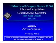
In this initial work, we focused on crossing the street in<br />
marked crosswalks across a one-way or two-way road with no<br />
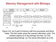
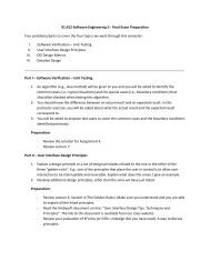
more than one lane in either direction. (See Fig. 1 <strong>for</strong> a<br />
diagram of the robot’s camera view at the curb. Fig. 2 shows<br />
an image from the robot’s left-facing camera.) Marked<br />
crosswalks are useful since they are likely to have curb cuts<br />
that will allow our wheeled robot to move safely into the street.<br />
From a curbside perspective, it is particularly difficult to detect<br />
and track vehicles in a multilane scenario due to the ways that<br />
vehicle occlusions can occur. Furthermore, although it is<br />
illegal to pass a stopped car at a crosswalk, this is a frequent<br />
cause of pedestrian accidents at multilane crossings.<br />
Statistically, intersections are very dangerous places to cross<br />
the street, so we have chosen to start with a safer place first. 1<br />
<strong>Tracking</strong> vehicles over time is fundamental to a streetcrossing<br />
algorithm. <strong>Tracking</strong> is needed to determine vehicle<br />
speed and what a vehicle is doing: accelerating or decelerating,<br />
approaching or leaving. Since vehicles are being tracked using<br />
motion, slow or stopped vehicles can “disappear.” The robot’s<br />
sonars and SICK laser scanner can detect vehicles in close<br />
proximity to the crosswalk. Additionally, since all vehicles are<br />
being tracked, we expect to see as many vehicles leaving on the<br />
right as entered from the left and vice versa.<br />
1 Note that the work is being done in Massachusetts, where no place is truly<br />
safe to cross.
marked crosswalk<br />
mobile robot<br />
curb cut<br />
Figure 1. <strong>Robot</strong>'s field of view from the left-facing camera (overhead view).<br />
Figure 2. <strong>Robot</strong>'s curbside perspective. Image taken with the left-facing<br />
camera.<br />
The system first begins tracking at the curb, in a stationary<br />
position. While determining whether it is safe to cross, the<br />
street-crossing system will devote equal processing to the left<br />
and right looking image streams. Vehicles approaching from<br />
either direction represent danger to the robot.<br />
Once the robot has entered the crosswalk, tracking is done<br />
while moving. Processing the left image stream is still<br />
necessary, but more processing is shifted to the right stream,<br />
which represents more danger to the crossing robot. Should the<br />
right side (far lane) become unsafe be<strong>for</strong>e the robot completes<br />
the street-crossing maneuver, the robot will stop short of the<br />
median strip and wait <strong>for</strong> vehicles in the far lane to yield or<br />
pass.<br />
This paper presents the algorithms developed <strong>for</strong> the<br />
vehicle tracking system.<br />
II. RELATED WORK<br />
<strong>System</strong>s that use computer vision to track vehicles in real<br />
time generally come under two major headings: automated<br />
driving systems [6–12] and systems that monitor and analyze<br />
traffic scenes [13–21]. Un<strong>for</strong>tunately, most methods from<br />
these domains are unsuitable or inappropriate <strong>for</strong> the streetcrossing<br />
problem.<br />
The vast majority of computer vision-based vehicle<br />
tracking algorithms take a model based [8, 9, 12, 20, 21] or<br />
template matching based approach [7, 10, 11, 22]. Use of a<br />
Kalman filter or Extended Kalman filter is quite common <strong>for</strong><br />
predictive tracking [8, 10, 11, 12, 15, 16, 20, 21]. The Kalman<br />
filter assumes a unimodal Gaussian distribution of the<br />
correlation feature and a constant velocity model, which limits<br />
its usefulness [22]. The use of models and/or templates almost<br />
certainly implies special off-line initializations. Typically,<br />
models and templates need to be trained be<strong>for</strong>e they can be<br />
used to track vehicles reliably. This, of course, depends on<br />
some cooperation from the real world. Poor training data will<br />
cause poor initial results. The off-line requirements and<br />
inherent computational overhead due to on-line updating make<br />
these approaches undesirable <strong>for</strong> the street-crossing algorithm.<br />
Domain-specific assumptions built into existing motion and<br />
scene models do not hold in a typical street-crossing scenario.<br />
We have a lower camera angle and do not have the relatively<br />
structured or uni<strong>for</strong>m appearance of a typical highway scene.<br />
Some traffic analysis systems use a homography or<br />
projective trans<strong>for</strong>m between image and world coordinates [15,<br />
16, 19]. This trans<strong>for</strong>m is useful <strong>for</strong> gathering traffic statistics<br />
such as vehicle count, speed and congestion. It requires off-line<br />
camera initialization or road markers to support on-line camera<br />
calibration. This is a reasonable approach in the context of<br />
fixed camera traffic surveillance systems, but invalid <strong>for</strong> a<br />
mobile robot.<br />
Some vehicle tracking systems exploit symmetries that<br />
arise from the viewing angle. For example, the rear view of a<br />
car from an autonomous vehicle is generally symmetric. These<br />
systems use models based on vehicle gray level or color<br />
symmetries and vehicle edge symmetries or aspect ratios [6, 7,<br />
9]. From the vantage point of a robot waiting to cross the<br />
street, the symmetry of an approaching or passing car is everchanging.<br />
Another type of symmetry is based on the relatively<br />
uni<strong>for</strong>m palette of gray values on the road surface [23, 24].<br />
Here is another assumption that is generally true of highways<br />
and generally false in a typical street-crossing scene. The road<br />
model needs to stay current with changing lighting conditions.<br />
Some systems use stereo vision <strong>for</strong> depth measurement [6].<br />
To use stereo, we would need to mount four cameras on our<br />
robot to get depth readings in both directions, making it
impractical. A single camera can compute depth maps using<br />
optical flow, but optical flow has been rejected by a number of<br />
researchers as being too expensive to compute in real time.<br />
Few vehicle tracking systems deal with shadow removal<br />
and/or vehicle occlusions. In the street crossing problem,<br />
shadows and occlusions are especially problematic due to the<br />
curbside camera angle. Some systems that measure vehicle<br />
speed depend on finding the geometric centers of tracked<br />
vehicles [14, 18], which implies the ability to segment vehicles<br />
perfectly; otherwise, the speed calculations would suffer. For<br />
example, a motion region could include overlapping vehicles or<br />
a vehicle and its shadow. This problem is less severe in the<br />
traffic analysis domain due to the overhead camera view, but<br />
an effective street crossing system must solve these issues.<br />
The ground plane constraint is used in a number of vehicle<br />
tracking systems [2, 3, 4, 5, 15, 16, 20]. This assumption is<br />
exploited in two ways in our tracking algorithm. Since we do<br />
not expect to detect vehicles above the horizon line, we do not<br />
need to raster scan <strong>for</strong> motion regions above the horizon line.<br />
This represents a significant data reduction without doing any<br />
processing. Lipton [22] uses the ground plane constraint to<br />
define a “depth ordering” which he uses to reason about the<br />
way vehicles can occlude one another. While our algorithm<br />
does not currently include explicit occlusion reasoning or<br />
disambiguation, we plan to add this in the future. The current<br />
algorithm implicitly deals with partial occlusions due to the<br />
way the bounding boxes are computed.<br />
A laser range finder has been used <strong>for</strong> measuring distance<br />
on the Navlab5 autonomous vehicle test bed [12]. Our research<br />
robot has a <strong>for</strong>ward looking SICK laser, but it is already<br />
delegated to the task of finding the curb cut on the far side of<br />
the street. To measure distance in both directions<br />
simultaneously, we would need two SICK lasers. Even if our<br />
research plat<strong>for</strong>m could support the weight and size of another<br />
laser, they are quite expensive. Radar is another possibility, but<br />
our robot is not currently equipped with a radar sensor.<br />
Almost all of the algorithms presented in the literature<br />
include some kind of lane masking or road boundary detection<br />
to limit the search space <strong>for</strong> vehicles. In the context of traffic<br />
analysis systems, highway lanes are generally straight and<br />
relatively easy to detect given the overhead camera view. In the<br />
context of autonomous highway vehicles, lane detection is<br />
fundamental to following the curvature of the road. Again, the<br />
camera view is conducive to detecting lane boundaries reliably<br />
as long as the road does not have sharp bends. The streetcrossing<br />
robot has a sidelong view of the roadway at street<br />
level. Perfect detection of the road boundaries requires some<br />
cooperation from the real world. The street must be generally<br />
flat, straight, and free of traffic at the time of detection; <strong>for</strong> this<br />
application, explicit road boundary detection is an unrealistic<br />
expectation. Implicitly, road boundaries are being detected as<br />
the left and right limits of motion in the scene. As a practical<br />
matter, it is unrealistic to assume that vehicles remain wholly<br />
within their lane at all times.<br />
III. VEHICLE DETECTION AND TRACKING ALGORITHM<br />
To detect vehicles, a number of processing steps are taken.<br />
Movement in the image is found by differencing successive<br />
frames of the scene. The differenced image is then filtered<br />
using a 3x3 median filter to remove noise and background<br />
motion. Edges are extracted using a Sobel edge detector. The<br />
highest edge points are candidates <strong>for</strong> a line marking the top of<br />
a car. The bottom of the car is found using Mori’s sign pattern.<br />
A. Image Differencing<br />
The principal tracking feature of the algorithm is motion.<br />
Image differencing is a common technique used <strong>for</strong> extracting<br />
scene motion. There are two general methods: reference frame<br />
differencing and interframe or temporal differencing. Both<br />
methods are sensitive to background and camera motion, but<br />
the reference frame (or background subtraction) method is<br />
unsuitable <strong>for</strong> a street-crossing robot. A reference frame must<br />
be grabbed when the scene is stationary and free of objects that<br />
could move while the tracking process is active. Alternatively,<br />
a reference frame could be computed by observing the constant<br />
parts of the image over time. Next, the reference frame needs to<br />
be updated on-line to stay current with lighting changes.<br />
Finally, whenever the robot moves, the reference frame<br />
becomes invalid. It is highly unlikely that the world will<br />
cooperate whenever the algorithm needs a clean reference<br />
frame.<br />
Our vehicle detection algorithm uses simple interframe<br />
differencing to extract motion regions from frame to frame.<br />
Some researchers have used a variation on simple image<br />
subtraction called “double differencing” (see, <strong>for</strong> example, [17,<br />
18]). The double difference method takes three consecutive<br />
frames, per<strong>for</strong>ms two subtractions against the middle frame,<br />
then ANDs the subtraction results to obtain a single motion<br />
image. Empirically, results were similar using double<br />
differencing and interframe differencing, so the faster method<br />
was selected.<br />
B. Noise Filtering<br />
A 3x3 median filter is used to remove camera noise and<br />
tiny flutters due to background motion. Most motion due to<br />
wind on trees and telephone wires is ignored by the assumption<br />
that vehicles stay in contact with the road plane. Filtering the<br />
difference image is more efficient than cleaning the raw camera<br />
images separately.<br />
C. Edge Extraction and Thresholding<br />
A Sobel edge detector is used to delineate the motion edges.<br />
Sobel is used frequently in the literature because it is efficient<br />
and provides generally good results. In the context of vehicle<br />
tracking, we expect to find mostly horizontal and vertical edges<br />
due to the typically rectangular contour of vehicles.<br />
The edge detected image is thresholded to extract the<br />
motion regions and facilitate raster scanning of the image.<br />
Experiments have used a fixed threshold value that worked<br />
well <strong>for</strong> the lighting condition. Histogram thresholding did not<br />
achieve a noticeably better result. Since (near-)optimal<br />
extraction of motion regions is essential to the success of this<br />
algorithm, work is continuing towards the inclusion of an<br />
adaptive thresholding method.
ounding boxes are sanity checked <strong>for</strong> things like negative<br />
height and unrealistic aspect ratios. Frame statistics such as<br />
number of vehicles (boxes) detected are stored in a frame<br />
object.<br />
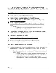
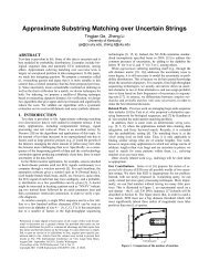
Figure 3. Result of Mori (white pixels) and roofline (black pixels) raster<br />
scans. Notice how the Mori scan detects the underneath of the vehicle without<br />
detecting the shadow region (which can be seen in the lighter gray color<br />
underneath the left car).<br />
D. Mori Scan<br />
Mori [2–5] describes a “sign pattern” <strong>for</strong> vehicle detection<br />
that is invariant to weather (lighting) and holds <strong>for</strong> wet and dry<br />
roads. Stated succinctly, the shadow underneath a vehicle is<br />
darker than any other point on the road. As Mori explains, if<br />
the shadow cast by a vehicle appears to be as dark as the<br />
shadow underneath a vehicle, this is “an illusion of brightness<br />
constancy.”<br />
Mori’s result has been used in a highway driving context<br />
[24]. Our algorithm uses Mori’s result to scan <strong>for</strong> vehicle<br />
bottoms in a single raw image (see Figure). The sign pattern is<br />
very useful <strong>for</strong> detecting vehicles while ignoring shadows.<br />
Be<strong>for</strong>e this was incorporated into the algorithm, shadows were<br />
handled in an ad hoc way, by eliminating short, wide bounding<br />
boxes as being caused by shadows. This simple rule eliminated<br />
most shadows effectively, but some shadows remained, which<br />
were sometimes grouped with a trailing vehicle and resulted in<br />
oversize bounding boxes. Use of the Mori result obviates the<br />
need <strong>for</strong> explicit shadow removal.<br />
E. Data Reduction and Abstract Data Types<br />
To support the vehicle detection algorithm, we define three<br />
abstract data types: lines, boxes, and (processed) frames. A<br />
line corresponds to the roofline of a vehicle. The fully<br />
segmented image is raster scanned from the horizon line<br />
downward to extract the highest motion pixels in the image<br />
plane. This pixel array is mined <strong>for</strong> lines; lines are defined as a<br />
minimum number of consecutive pixels such that the row<br />
coordinate of adjacent pixels does not differ by more than a<br />
specified value. The line finding algorithm tolerates a specified<br />
percentage of outlier pixels. If too many lines are rejected<br />
during the line-mining process, either because they're too short<br />
or have too many outlier pixels, the whole processed frame is<br />
rejected. A high number of rejected lines indicates that a frame<br />
is too noisy to be useful <strong>for</strong> tracking in<strong>for</strong>mation.<br />
Fig. 3 shows the result of the processing once the roofline<br />
and Mori scans have been completed. An efficient downward<br />
and outward scan starting at either end of a roofline finds the<br />
vehicle sides. Finally, the data from the Mori scan is added to<br />
completely determine a vehicle's bounding box. The computed<br />
F. History <strong>Tracking</strong><br />
The algorithm includes a history component that supports<br />
the actual tracking of detected vehicles. Assuming a fast frame<br />
rate, a tracked vehicle does not move very far in the image<br />
plane from frame to frame. Segmentation can be flawed, due to<br />
camera noise and extraneous motion in the scene, but we can<br />
use a vehicle’s history to smooth the results. For example, a<br />
vehicle that has been approaching the robot <strong>for</strong> a number of<br />
frames can not spontaneously reverse direction and go the other<br />
way, even if the bounding box suggests otherwise.<br />
IV. RESULTS<br />
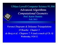
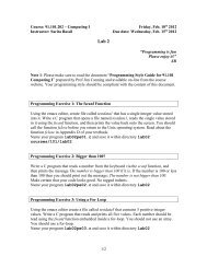
Vehicle detection results are shown in Fig. 4. This figure<br />
shows six frames from a video sequence from the robot’s leftfacing<br />
camera. The white boxes drawn on the images represent<br />
the bounding boxes of the tracked vehicles found by our<br />
algorithm. The algorithm is able to track multiple cars, both<br />
approaching and driving away from the robot. Cars that are<br />
very far in the distance, such as the second approaching car in<br />
the first two frames shown, are not detected because their roofs<br />
do not have enough pixels to mark the line as a roofline.<br />
However, once the car gets a bit closer, it is detected. When<br />
the second approaching car is detected in the third frame of the<br />
tracking sequence, it is still approximately 150 feet away from<br />
the camera.<br />
The sequence also shows the occlusion of the passing car in<br />
the far lane by the approaching SUV. In the first two frames of<br />
the sequence, the approaching SUV and passing car are<br />
computed as separate bounding boxes. In the third frame, the<br />
two cars are merged into one box. Looking closely at the<br />
image, you can see that the top of the passing car is almost at<br />
the same height as the SUV’s hood. In the next two images,<br />
the passing car is completely occluded by the SUV. Finally, in<br />
the last image, the algorithm has redetected the passing car as it<br />
emerges from behind the SUV.<br />
The image sequence is only displaying the bounding boxes<br />
found, not the system’s hypothesis about the direction of each<br />
vehicle computed by the history tracking algorithm. When<br />
deciding if it is safe to cross, direction in<strong>for</strong>mation would be<br />
used.<br />
The current system does not run at frame rate, but we are<br />
currently running on large images (720 x 480 pixels). As<br />
development continues, we will use smaller image sizes.<br />
Additionally, we are optimizing the algorithm.<br />
V. CONCLUSIONS AND FUTURE WORK<br />
The current tracking algorithm is able to identify vehicles in<br />
two lanes, one moving towards and one moving away from the<br />
robot’s camera. Multiple vehicles can be found traveling in<br />
both lanes.
Figure 4. Six frames from a video sequence of approaching and passing vehicles from the robot’s left-facing camera. The white boxes show the cars found by<br />
the tracking algorithm. The sequence shows the detection of a second approaching car as it gets closer. It also shows a passing car being tracked, then occluded<br />
by the oncoming vehicle, then finally tracked again as it emerges from behind the oncoming vehicle.<br />
We are starting to use the tracking results <strong>for</strong> actual<br />
crossings. The robot will need to choose a safe starting time.<br />
Then, as it moves across the street, it will need to continue<br />
tracking vehicles to update its safety measure.<br />
Extensions to the current system could include multilane<br />
and intersection crossings. For these extensions, other scene<br />
features could be used as clues to find safe crossing locations<br />
and safe crossing times. For example, the robot could decide to<br />
follow a pedestrian across the street. Traffic light changes<br />
could also be used to help the system reason about safe<br />
crossing times.<br />
REFERENCES<br />
[1] H. A. Yanco, “Shared user-computer control of a robotic wheelchair<br />
system,” Ph.D. Thesis, Department of Electrical Engineering and<br />
Computer Science, Massachusetts Institute of Technology, September<br />
2000.<br />
[2] N. M. Charkari, K. Ishii, and H. Mori, “Proper selection of sonar and<br />
visual sensors <strong>for</strong> vehicle detection and avoidance,” Proceedings of the<br />
IEEE/RSJ/GI International Conference on Intelligent <strong>Robot</strong>s and<br />
<strong>System</strong>s, Vol. 2 , 12-16 Sept. 1994, pp. 1110 –1117.<br />
[3] N. M. Charkari and H. Mori, “A new approach <strong>for</strong> real time moving<br />
vehicle detection,” Proceedings of the 1993 IEEE/RSJ International<br />
Conference on Intelligent <strong>Robot</strong>s and <strong>System</strong>s, Vol. 1, 26-30 July 1993,<br />
pp. 273 – 278.<br />
[4] H. Mori and N. M. Charkari, “Shadow and rhythm as sign patterns of<br />
obstacle detection,” International Symposium on Industrial Electronics,<br />
1993, pp. 271--277.<br />
[5] H. Mori, N. M. Charkari, T. Matsushita, “On-line vehicle and pedestrian<br />
detection based on sign pattern,” IEEE Trans. on Industrial Electronics,<br />
Vol. 41, No. 4, pp. 384-391, Aug. 1994.<br />
[6] M. Bertozzi, A. Broggi, A. Fascioli, and S. Nichele, “Stereo visionbased<br />
vehicle detection,” IEEE Intelligent Vehicles Symposium, Detroit,<br />
MI, October 2000, pp. 39-44.<br />
[7] M. Betke, E. Haritaoglu, and L. Davis, “Highway scene analysis in hard<br />
real-time,” Intelligent Transportation <strong>System</strong>s, IEEE, July 1997.<br />
[8] F. Dellaert and C. Thorpe, “Robust car tracking using Kalman filtering<br />
and Bayesian templates,” Proc. of the SPIE - Int. Soc. Opt. Eng., Vol.<br />
3207, October 1997.<br />
[9] U. Regensburger and V. Graefe, “Visual recognition of obstacles on<br />
roads,” Proc. IROS '94, pp. 980–987, Munich, Germany, 1994.<br />
[10] M. B. van Leeuwen and F. C. A. Groen, “A plat<strong>for</strong>m <strong>for</strong> robust real-time<br />
vehicle tracking using decomposed templates,” Intelligent Autonomous<br />
<strong>System</strong>s Group, Faculty of Science, University of Amsterdam,<br />
Amsterdam, The Netherlands, unpublished.<br />
[11] M.B. van Leeuwen and F.C.A. Groen, “Vehicle detection with a mobile<br />
camera,” Intelligent Autonomous <strong>System</strong>s Group, Faculty of Science,<br />
University of Amsterdam, Amsterdam, The Netherlands, unpublished.<br />
[12] L. Zhao and C. Thorpe. “Qualitative and quantitative car tracking from a<br />
range image sequence,” Computer <strong>Vision</strong> and Pattern Recognition,<br />
pages 496-501, 1998.<br />
[13] L. A. Alexandre and A. C. Campilho, “A 2D image motion detection<br />
method using a stationary camera,” RECPAD98, 10th Portuguese<br />
Conference on Pattern Recognition, Lisbon, Portugal, 1998.<br />
[14] E. Atkociunas and M. Kazimianec, “Aspects in traffic control system<br />
development,” Vilnius University, Faculty of Mathematics and<br />
In<strong>for</strong>matics, Jyvaskyla, 2002.<br />
[15] B. Coifman, D. Beymer, P. McLauchlan, and J. Malik. “A real-time<br />
computer vision system <strong>for</strong> vehicle tracking and traffic surveillance,”<br />
Transportation Research: Part C, vol 6, no 4, 1998, pp 271-288.<br />
[16] D. Beymer, P. McLauchlan, B. Coifman, and J. Malik, “A realtime<br />
computer vision system <strong>for</strong> measuring traffic parameters,” Proceedings<br />
of IEEE Conference on Computer <strong>Vision</strong> and Pattern Recognition, 1997.<br />
[17] R. Cucchiara, M. Piccardi, A. Prati, and N. Scarabottolo, “Real-time<br />
detection of moving vehicles,” Proc International Conference on Image<br />
Analysis and Processing, Venice, Italy, pp. 618 – 623, September 1999.<br />
[18] D.J. Dailey and L. Li, “Video image processing to create a speed<br />
sensor,” ITS Research Program, Final Research Report, College of<br />
Engineering, University of Washington, Seattle, Washington, March<br />
1999.<br />
[19] N. Ferrier, S. Rowe, and A. Blake, “Real-time traffic monitoring,” Proc.<br />
2nd IEEE Workshop on Applications of Computer <strong>Vision</strong>, pp. 81–88,<br />
1994.<br />
[20] D. Koller, J. Weber, T. Huang, J. Malik, G. Ogasawara, B. Rao, S.<br />
Russel, “Towards robust automatic traffic scene analysis in real-time,”<br />
Proc. Int'l Conf. Pattern Recognition, pp. 126–131, 1994.
[21] D. R. Magee, “<strong>Tracking</strong> multiple vehicles using <strong>for</strong>eground, background<br />
and motion models,” University of Leeds, School of Computer Studies,<br />
Research Report Series, (Submitted to European Conference on<br />
Computer <strong>Vision</strong>, May 2002), December 2001.<br />
[22] A. J. Lipton, H. Fujiyoshi, and R. S. Patil, “Moving target classification<br />
and tracking from real time video,” IEEE Workshop on Application of<br />
Computer <strong>Vision</strong>, pp. 8–14, 1998.<br />
[23] M. Betke and H. Nguyen, “Highway scene analysis from a moving<br />
vehicle under reduced visibility conditions,” Proc. of the International<br />
Conference on Intelligent Vehicles, IEEE Industrial Electronics Society,<br />
Stuttgart, Germany pp. 131–136. Oct. 1998.<br />
[24] C. Tzomakas and W. von Seelen, “Vehicle detection in traffic scenes<br />
using shadows,” Internal Report IRINI 98-06, Institut fur<br />
Neuroin<strong>for</strong>matik, Ruhr-Universitat Bochum, Germany, August 1998.