Refrigeration Piping Charging Residential AirConditioning R
Refrigeration Piping Charging Residential AirConditioning R
Refrigeration Piping Charging Residential AirConditioning R

Create successful ePaper yourself
Turn your PDF publications into a flip-book with our unique Google optimized e-Paper software.
5<br />
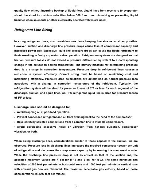
gravity flow without incurring backup of liquid flow. Liquid lines from receivers to evaporator<br />
should be sized to maintain velocities below 300 fpm, thus minimizing or preventing liquid<br />
hammer when solenoids or other electrically operated valves are used.<br />
Refrigerant Line Sizing<br />
In sizing refrigerant lines, cost considerations favor keeping line size as small as possible.<br />
However, suction and discharge line pressure drops cause loss of compressor capacity and<br />
increased power use. Excessive liquid line pressure drops can cause the liquid refrigerant to<br />
flash, resulting in faulty expansion valve operation. <strong>Refrigeration</strong> systems are designed so that<br />
friction pressure losses do not exceed a pressure differential equivalent to a corresponding<br />
change in the saturation boiling temperature. The primary measure for determining pressure<br />
drop is a change in saturation temperature. Pressure drop in refrigerant lines causes a<br />
reduction in system efficiency. Correct sizing must be based on minimizing cost and<br />
maximizing efficiency. Pressure drop calculations are determined as normal pressure loss<br />
associated with a change in saturation temperature of the refrigerant. Typically, the<br />
refrigeration system will be sized for pressure losses of 2ºF or less for each segment of the<br />
discharge, suction, and liquid lines. An HFC refrigerant liquid line is sized for pressure losses<br />
of 1ºF or less.<br />
Discharge lines should be designed to:<br />
• Avoid trapping oil at part-load operation.<br />
• Prevent condensed refrigerant and oil from draining back to the head of the compressor.<br />
• Have carefully selected connections from a common line to multiple compressors.<br />
• Avoid developing excessive noise or vibration from hot-gas pulsation, compressor<br />
vibration, or both.<br />
When sizing discharge lines, considerations similar to those applied to the suction line are<br />
observed. Pressure loss in discharge lines increases the required compressor power per unit<br />
of refrigeration and decreases the compressor capacity by increasing the compression ratio.<br />
While the discharge line pressure drop is not as critical as that of the suction line, the<br />
accepted maximum values are 4 psi for R-12 and 6 psi for R-22. The same minimum gas<br />
velocities of 500 feet per minute in horizontal runs and 1000 feet per minute in vertical runs<br />
with upward gas flow are observed. The maximum acceptable gas velocity, based on noise<br />
considerations, is 4000 feet per minute.<br />
5