IS-L606 - Watts Fluid Air
IS-L606 - Watts Fluid Air
IS-L606 - Watts Fluid Air

You also want an ePaper? Increase the reach of your titles
YUMPU automatically turns print PDFs into web optimized ePapers that Google loves.
Pneumatic Division<br />
Richland, Michigan 49083<br />
269-629-5000<br />
Installation & Service Instructions<br />
<strong>IS</strong>-<strong>L606</strong><br />
<strong>L606</strong> Lubricator<br />
<strong>IS</strong>SUED: April, 2008<br />
Supersedes: September, 2007<br />
Doc. #<strong>IS</strong><strong>L606</strong>, EN #080254, Rev. 4<br />
!<br />
WARNING<br />
To avoid unpredictable system behavior that can cause personal injury<br />
and property damage:<br />
• Disconnect electrical supply (when necessary) before installation,<br />
servicing, or conversion.<br />
• Disconnect air supply and depressurize all air lines connected to this<br />
product before installation, servicing, or conversion.<br />
• Operate within the manufacturer’s specified pressure, temperature,<br />
and other conditions listed in these instructions.<br />
• Medium must be moisture-free if ambient temperature is below<br />
freezing.<br />
• Service according to procedures listed in these instructions.<br />
• Installation, service, and conversion of these products must be<br />
performed by knowledgeable personnel who understand how<br />
pneumatic products are to be applied.<br />
• After installation, servicing, or conversion, air and electrical supplies<br />
(when necessary) should be connected and the product tested for<br />
proper function and leakage. If audible leakage is present, or the<br />
product does not operate properly, do not put into use.<br />
• Warnings and specifications on the product should not be covered by<br />
paint, etc. If masking is not possible, contact your local representative<br />
for replacement labels.<br />
! CAUTION<br />
Polyurethane bowls, being transparent and tough, are ideal for use with Filters<br />
and Lubricators. They are suitable for use in normal industrial environments, but<br />
should not be located in areas where they could be subjected to direct sunlight,<br />
an impact blow, nor temperatures outside of the rated range. As with most<br />
plastics, some chemicals can cause damage. Polyurethane bowls should not<br />
be exposed to chlorinated hydrocarbons, ketones, esters and certain alcohols.<br />
They should not be used in air systems where compressors are lubricated with<br />
fire-resistant fluids such as phosphate ester and di-ester types.<br />
Metal bowls are recommended where ambient and/or media conditions are not<br />
compatible with polyurethane bowls. Metal bowls resist the action of most such<br />
solvents, but should not be used where strong acids or bases are present or<br />
in salt laden atmospheres. Consult the factory for specific recommendations<br />
where these conditions exist.<br />
TO CLEAN POLYURETHANE BOWLS USE MILD SOAP AND WATER<br />
ONLY! DO NOT use cleansing agents such as acetone, benzene, carbon<br />
tetrachloride, gasoline, toluene, etc., which are damaging to this plastic.<br />
Bowl guards are recommended for added protection of polyurethane bowls where<br />
chemical attack may occur.<br />
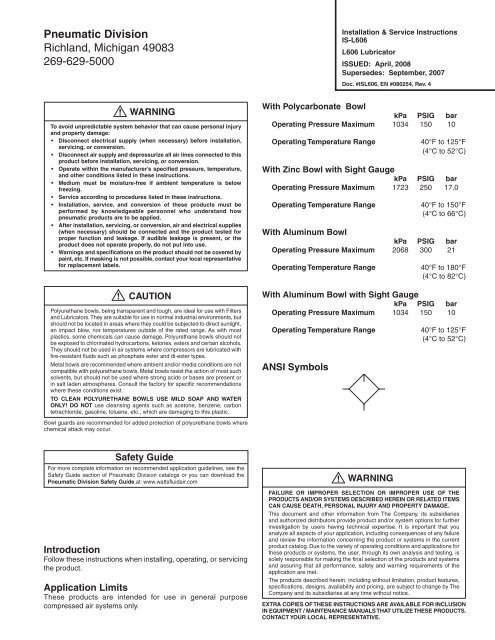
With Polycarbonate Bowl<br />
kPa PSIG bar<br />
Operating Pressure Maximum 1034 150 10<br />
Operating Temperature Range 40°F to 125°F<br />
(4°C to 52°C)<br />
With Zinc Bowl with Sight Gauge<br />
kPa PSIG bar<br />
Operating Pressure Maximum 1723 250 17.0<br />
Operating Temperature Range 40°F to 150°F<br />
(4°C to 66°C)<br />
With Aluminum Bowl<br />
kPa PSIG bar<br />
Operating Pressure Maximum 2068 300 21<br />
Operating Temperature Range 40°F to 180°F<br />
(4°C to 82°C)<br />
With Aluminum Bowl with Sight Gauge<br />
kPa PSIG bar<br />
Operating Pressure Maximum 1034 150 10<br />
Operating Temperature Range 40°F to 125°F<br />
(4°C to 52°C)<br />
ANSI Symbols<br />
Safety Guide<br />
For more complete information on recommended application guidelines, see the<br />
Safety Guide section of Pneumatic Division catalogs or you can download the<br />
WARNING<br />
Pneumatic Division Safety Guide at: www.wattsfluidair.com !<br />
Introduction<br />
Follow these instructions when installing, operating, or servicing<br />
the product.<br />
Application Limits<br />
These products are intended for use in general purpose<br />
compressed air systems only.<br />
FAILURE OR IMPROPER SELECTION OR IMPROPER USE OF THE<br />
PRODUCTS AND/OR SYSTEMS DESCRIBED HEREIN OR RELATED ITEMS<br />
CAN CAUSE DEATH, PERSONAL INJURY AND PROPERTY DAMAGE.<br />
This document and other information from The Company, its subsidiaries<br />
and authorized distributors provide product and/or system options for further<br />
investigation by users having technical expertise. It is important that you<br />
analyze all aspects of your application, including consequences of any failure<br />
and review the information concerning the product or systems in the current<br />
product catalog. Due to the variety of operating conditions and applications for<br />
these products or systems, the user, through its own analysis and testing, is<br />
solely responsible for making the final selection of the products and systems<br />
and assuring that all performance, safety and warning requirements of the<br />
application are met.<br />
The products described herein, including without limitation, product features,<br />
specifications, designs, availability and pricing, are subject to change by The<br />
Company and its subsidiaries at any time without notice.<br />
EXTRA COPIES OF THESE INSTRUCTIONS ARE AVAILABLE FOR INCLUSION<br />
IN EQUIPMENT / MAINTENANCE MANUALS THAT UTILIZE THESE PRODUCTS.<br />
CONTACT YOUR LOCAL REPRESENTATIVE.
<strong>L606</strong> Lubricator<br />
Installation<br />
1. The lubricator should be installed with reasonable accessibility<br />
for service whenever possible – repair service kits are available.<br />
Keep pipe or tubing lengths to a minimum with inside clean<br />
and free of dirt and chips. Pipe joint compound should be used<br />
sparingly and applied only to the male pipe – never into the<br />
female port. Do not use PTFE tape to seal pipe joints – pieces<br />
have a tendency to break off and lodge inside the unit, possibly<br />
causing malfunction. Also, new pipe or hose should be installed<br />
between the lubricator and equipment being lubricated.<br />
2. The upstream pipe work must be clear of accumulated dirt and<br />
liquids.<br />
3. Select a lubricator location as close as possible to the equipment<br />
being lubricated and downstream of any pressure regulator.<br />
4. Install lubricator so that air flows in the direction of arrow on<br />
body.<br />
5. Install lubricator vertically with bowl drain mechanism (if supplied)<br />
at the bottom.<br />
Dip Tube<br />
Check Ball<br />
Button Head<br />
Fill Fitting<br />
Fill Plug<br />
(Brass)<br />
Fill Plug<br />
(Plastic)<br />
Adjusting Knob<br />
Needle Valve<br />
Assembly<br />
Valve Seat<br />
O-ring<br />
Sight Dome<br />
O-ring<br />
Body<br />
O-ring<br />
Collar<br />
(Flange Ring)<br />
<strong>IS</strong>-<strong>L606</strong><br />
Operation and Service<br />
1. Filling — Lubricators can be filled while under pressure and<br />
without shutting down equipment. Slowly remove either fill<br />
plug and fill to 1/4" to top of bowl using correct oil. For proper<br />
automatic fill operation, the oil inlet pressure to lubricator must<br />
be maintained between 10 and 200 PSI above air pressure to<br />
lubricator.<br />
Suggested Lubricant: F442<br />
Petroleum based oil of 100 to 200 SSU viscosity at 100°F and an<br />
aniline point greater than 200°F. (Mobil DTE24 and Sun Company<br />
Sunvis 932 are good examples). Do not use oils with adhesives,<br />
compound oils containing solvents, graphite, detergents or<br />
synthetic oils.<br />
2. Replace the Fill Plug (by turning clockwise) and seat firmly.<br />
Excessive torque is not required. Turn on air supply, if leakage<br />
occurs, DO NOT OPERATE — conduct repairs again. The<br />
lubricator is now ready for setting.<br />
3. Oil Delivery Adjustment — To adjust oil delivery, turn Adjustment<br />
Knob on top of the lubricator.<br />
Leaner — Clockwise<br />
Richer — Counterclockwise<br />
By counting the number of drops per minute in the Sight Dome,<br />
you can adjust to your requirements. Generally, one drop per<br />
minute downstream for every 10 - 15 SCFM flow is satisfactory.<br />
25 drops per minute equals one (1) ounce per hour - volume of<br />
oil passing through the Sight Dome.<br />
NOTE: This is a constant density type lubricator which delivers<br />
a constant ratio of oil air flow. Therefore, if air flow increases<br />
or decreases, oil delivery will be adjusted proportionately.<br />
ONLY IF A DIFFERENT RATIO <strong>IS</strong> DESIRED SHOULD YOUR<br />
ADJUSTMENT KNOB SETTING BE CHANGED AFTER YOUR<br />
INITIAL SETTING.<br />
4. Cleaning — Erratic lubricator operation or loss of lubrication is<br />
almost always due to dirt (rust, pipe tape, etc.) in the needle valve<br />
or venturi area. To clean, shut off and vent all air line pressure to<br />
the unit being cleaned. In most cases cleaning is needed only in<br />
the oil metering area. Pull off Adjusting Knob and remove Needle<br />
Valve Assembly by turning out large hex nut. Remove Needle<br />
Valve Seat and clean removed parts with alcohol making sure<br />
hole in seat is clear. With a #57 drill, make sure hole in bottom<br />
of sight gauge area is open. Remove Bowl. Clean parts with<br />
soapy water or denatured alcohol but do not use denatured<br />
alcohol on plastic bowl, sight dome or sight gauge. If using<br />
compressed air to blow dry, be sure to wear appropriate eye<br />
protection.<br />
5. After servicing, apply system pressure and check for air leaks. If<br />
leakage occurs, Do Not Operate — conduct servicing again.<br />
Lightly grease with provided lubricant.<br />
Dip Tube<br />
Sight Gauge<br />
Bowl<br />
Inspect for nicks, scratches, and surface imperfections.<br />
If present, reduced service life is probable and future<br />
replacement should be planned.<br />
Clean with lint-free cloth.<br />
Kits Available<br />
Product Bowl Port<br />
Description Number Type Size<br />
Bowl<br />
Polycarbonate BK606Y B 1/4", 3/8"<br />
Zinc with Sight Gauge BK605WY W 1/4", 3/8"<br />
Polycarbonate BK606A B 1/2"<br />
Aluminum BK603A E 1/2"<br />
Zinc with Sight Gauge BK605WA W 1/2"<br />
Aluminum with Sight Gauge BK606X30A G 1/2"<br />
Aluminum BK603B E 3/4" thru 1-1/2"<br />
Zinc with Sight Gauge BK605WB W 3/4" thru 1-1/2"<br />
Aluminum with Sight Gauge BK606X30B G 3/4" thru 1-1/2"<br />
Repair Kit<br />
Dip Tube Replacement Kit DTK606 All All Sizes<br />
Needle Valve Assembly RK606Y All All Sizes<br />
Sight Dome Repair Kit RK606SY All All Sizes<br />
Sight Gauge Bowl Repair Kit RBK605WY W 1/4", 3/8"<br />
Sight Gauge Bowl Repair Kit RKB605WA W 1/2"<br />
Sight Gauge Bowl Repair Kit RKB606X30A G 1/2"<br />
Sight Gauge Bowl Repair Kit RKB606WB W 3/4" thru 1-1/2"<br />
Sight Gauge Bowl Repair Kit RKB606X30B G 3/4" thru 1-1/2"<br />
Button Head Fill Fitting (3/4 Hex.) SAA606C109-1 — —<br />
Button Head Fill Fitting (11/16 Hex.) <strong>L606</strong>C14 — —<br />
Fill Plug (Brass) SA606B4 — —<br />
Fill Plug (Plastic) SAP04113 — —