IS-L606 (Lubricator) 0705.pmd - Watts Fluid Air
IS-L606 (Lubricator) 0705.pmd - Watts Fluid Air
IS-L606 (Lubricator) 0705.pmd - Watts Fluid Air

Create successful ePaper yourself
Turn your PDF publications into a flip-book with our unique Google optimized e-Paper software.
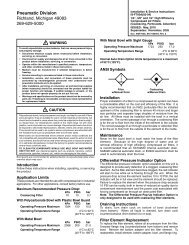
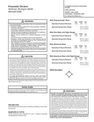
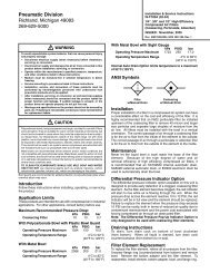
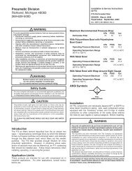
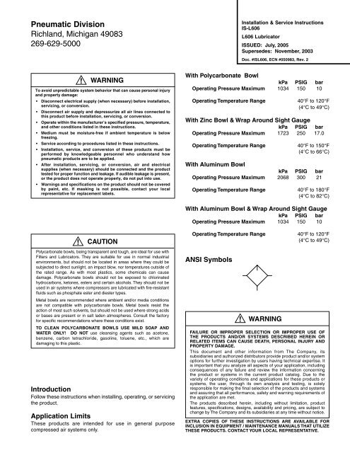
Pneumatic DivisionRichland, Michigan 49083269-629-5000Installation & Service Instructions<strong>IS</strong>-<strong>L606</strong><strong>L606</strong> <strong>Lubricator</strong><strong>IS</strong>SUED: July, 2005Supersedes: November, 2003Doc. #<strong>IS</strong><strong>L606</strong>, ECN #050983, Rev. 2!WARNINGTo avoid unpredictable system behavior that can cause personal injuryand property damage:• Disconnect electrical supply (when necessary) before installation,servicing, or conversion.• Disconnect air supply and depressurize all air lines connected tothis product before installation, servicing, or conversion.• Operate within the manufacturer’s specified pressure, temperature,and other conditions listed in these instructions.• Medium must be moisture-free if ambient temperature is belowfreezing.• Service according to procedures listed in these instructions.• Installation, service, and conversion of these products must beperformed by knowledgeable personnel who understand howpneumatic products are to be applied.• After installation, servicing, or conversion, air and electricalsupplies (when necessary) should be connected and the producttested for proper function and leakage. If audible leakage is present,or the product does not operate properly, do not put into use.• Warnings and specifications on the product should not be coveredby paint, etc. If masking is not possible, contact your localrepresentative for replacement labels.With Polycarbonate BowlkPa PSIG barOperating Pressure Maximum 1034 150 10Operating Temperature Range 40°F to 120°F(4°C to 49°C)With Zinc Bowl & Wrap Around Sight GaugekPa PSIG barOperating Pressure Maximum 1723 250 17.0Operating Temperature Range 40°F to 150°F(4°C to 66°C)With Aluminum BowlkPa PSIG barOperating Pressure Maximum 2068 300 21Operating Temperature Range 40°F to 180°F(4°C to 82°C)With Aluminum Bowl & Wrap Around Sight GaugekPa PSIG barOperating Pressure Maximum 1034 150 10!CAUTIONPolycarbonate bowls, being transparent and tough, are ideal for use withFilters and <strong>Lubricator</strong>s. They are suitable for use in normal industrialenvironments, but should not be located in areas where they could besubjected to direct sunlight, an impact blow, nor temperatures outside ofthe rated range. As with most plastics, some chemicals can causedamage. Polycarbonate bowls should not be exposed to chlorinatedhydrocarbons, ketones, esters and certain alcohols. They should not beused in air systems where compressors are lubricated with fire-resistantfluids such as phosphate ester and diester types.Metal bowls are recommended where ambient and/or media conditionsare not compatible with polycarbonate bowls. Metal bowls resist theaction of most such solvents, but should not be used where strong acidsor bases are present or in salt laden atmospheres. Consult the factoryfor specific recommendations where these conditions exist.TO CLEAN POLYCARBONATE BOWLS USE MILD SOAP ANDWATER ONLY! DO NOT use cleansing agents such as acetone,benzene, carbon tetrachloride, gasoline, toluene, etc., which aredamaging to this plastic.IntroductionFollow these instructions when installing, operating, or servicingthe product.Application LimitsThese products are intended for use in general purposecompressed air systems only.Operating Temperature Range 40°F to 120°F(4°C to 49°C)ANSI Symbols!WARNINGFAILURE OR IMPROPER SELECTION OR IMPROPER USE OFTHE PRODUCTS AND/OR SYSTEMS DESCRIBED HEREIN ORRELATED ITEMS CAN CAUSE DEATH, PERSONAL INJURY ANDPROPERTY DAMAGE.This document and other information from The Company, itssubsidiaries and authorized distributors provide product and/or systemoptions for further investigation by users having technical expertise. Itis important that you analyze all aspects of your application, includingconsequences of any failure and review the information concerningthe product or systems in the current product catalog. Due to thevariety of operating conditions and applications for these products orsystems, the user, through its own analysis and testing, is solelyresponsible for making the final selection of the products and systemsand assuring that all performance, safety and warning requirements ofthe application are met.The products described herein, including without limitation, productfeatures, specifications, designs, availability and pricing, are subject tochange by The Company and its subsidiaries at any time without notice.EXTRA COPIES OF THESE INSTRUCTIONS ARE AVAILABLE FORINCLUSION IN EQUIPMENT / MAINTENANCE MANUALS THAT UTILIZETHESE PRODUCTS. CONTACT YOUR LOCAL REPRESENTATIVE.
<strong>L606</strong> <strong>Lubricator</strong>Installation1. The lubricator should be installed with reasonable accessibilityfor service whenever possible – repair service kits are available.Keep pipe or tubing lengths to a minimum with inside clean andfree of dirt and chips. Pipe joint compound should be usedsparingly and applied only to the male pipe – never into thefemale port. Do not use PTFE tape to seal pipe joints – pieceshave a tendency to break off and lodge inside the unit, possiblycausing malfunction. Also, new pipe or hose should be installedbetween the lubricator and equipment being lubricated.2. The upstream pipe work must be clear of accumulated dirt andliquids.3. Select a lubricator location as close as possible to the equipmentbeing lubricated and downstream of any pressure regulator.4. Install lubricator so that air flows in the direction of arrow on body.5. Install lubricator vertically with bowl drain mechanism (if supplied)at the bottom.Dip TubeCheck BallButton HeadFill FittingFill PlugAdjusting KnobNeedle ValveAssemblyValve SeatO-ringSight DomeO-ringBodyO-ring<strong>IS</strong>-<strong>L606</strong>Collar(Flange Ring)Operation and Service1. Filling — <strong>Lubricator</strong>s can be filled while under pressure andwithout shutting down equipment. Slowly remove either fill plugand fill to 1/4" to top of bowl using correct oil. For proper automaticfill operation, the oil inlet pressure to lubricator must be maintainedbetween 10 and 200 PSI above air pressure to lubricator.Suggested Lubricant: F442Petroleum based oil of 100 to 200 SSU viscosity at 100°F andan aniline point greater than 200°F. (Mobil DTE24 and SunCompany Sunvis 932 are good examples). Do not use oils withadhesives, compound oils containing solvents, graphite,detergents or synthetic oils.2. Replace the Fill Plug (by turning clockwise) and seat firmly.Excessive torque is not required. Turn on air supply, if leakageoccurs, DO NOT OPERATE — conduct repairs again. Thelubricator is now ready for setting.3. Oil Delivery Adjustment — To adjust oil delivery, turn AdjustmentKnob on top of the lubricator.Leaner — ClockwiseRicher — CounterclockwiseBy counting the number of drops per minute in the Sight Dome,you can adjust to your requirements. Generally, one drop perminute downstream for every 10 - 15 SCFM flow is satisfactory.25 drops per minute equals one (1) ounce per hour - volume ofoil passing through the Sight Dome.NOTE: This is a constant density type lubricator which deliversa constant ratio of oil air flow. Therefore, if air flow increases ordecreases, oil delivery will be adjusted proportionately. ONLY IFA DIFFERENT RATIO <strong>IS</strong> DESIRED SHOULD YOURADJUSTMENT KNOB SETTING BE CHANGED AFTER YOURINITIAL SETTING.4. Cleaning — Erratic lubricator operation or loss of lubrication isalmost always due to dirt (rust, pipe tape, etc.) in the needlevalve or venturi area. To clean, shut off and vent all air linepressure to the unit being cleaned. In most cases cleaning isneeded only in the oil metering area. Pull off Adjusting Knob andremove Needle Valve Assembly by turning out large hex nut.Remove Needle Valve Seat and clean removed parts with alcoholmaking sure hole in seat is clear. With a #57 drill, make surehole in bottom of sight gauge area is open. Remove Bowl. Cleanparts with soapy water or denatured alcohol but do not usedenatured alcohol on plastic bowl, sight dome or sightgauge. If using compressed air to blow dry, be sure to wearappropriate eye protection.5. After servicing, apply system pressure and check for air leaks. Ifleakage occurs, Do Not Operate — conduct servicing again.Lightly grease with provided lubricant.Dip TubeSight GaugeBowlInspect for nicks, scratches, and surface imperfections.If present, reduced service life is probable and futurereplacement should be planned.Clean with lint-free cloth.Kits AvailableProduct Bowl PortDescription Number Type SizeBowlPolycarbonate BK606Y B 1/4", 3/8"Zinc with Sight Gauge BK609WY W 1/4", 3/8"Polycarbonate BK606A B 1/2"Aluminum BK603A E 1/2"Zinc with Sight Gauge BK609WA W 1/2"Aluminum with Sight Gauge BK606X30A G 1/2"Aluminum BK603B E 3/4" thru 1-1/2"Zinc with Sight Gauge BK609WB W 3/4" thru 1-1/2"Aluminum with Sight Gauge BK606X30B G 3/4" thru 1-1/2"Repair KitDip Tube Replacement Kit DTK606 All All SizesNeedle Valve Assembly RK606Y All All SizesSight Dome Repair Kit RK606SY All All SizesSight Gauge Bowl Repair Kit RBK605WY W 1/4", 3/8"Sight Gauge Bowl Repair Kit RKB605WA W 1/2"Sight Gauge Bowl Repair Kit RKB606X30A G 1/2"Sight Gauge Bowl Repair Kit RKB606WB W 3/4" thru 1-1/2"Sight Gauge Bowl Repair Kit RKB606X30B G 3/4" thru 1-1/2"Button Head Fill Fitting SAA606C109-1 — —Fill Plug SA60684 — —