View Product Sample - FordManuals.com
View Product Sample - FordManuals.com
View Product Sample - FordManuals.com

You also want an ePaper? Increase the reach of your titles
YUMPU automatically turns print PDFs into web optimized ePapers that Google loves.
Copyright © 2008, Forel Publishing Company, LLC, Woodbridge, Virginia<br />
All Rights Reserved. No part of this book may be used or reproduced in any manner whatsoever<br />
without written permission of Forel Publishing Company, LLC. For information write to Forel<br />
Publishing Company, LLC, 3999 Peregrine Ridge Ct., Woodbridge, VA 22192<br />
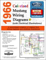
1969 Colorized Mustang Wiring and Vacuum Diagrams<br />
(Extracted from Form 7098-69-3, Form FD-7795P-69, FD-7943-69,<br />
FP-7635B, and FD-7943-G)<br />
EAN: 978-1-60371-028-2<br />
ISBN: 1-60371-028-0<br />
Forel Publishing Company, LLC<br />
3999 Peregrine Ridge Ct.<br />
Woodbridge, VA 22192<br />
Email address: webmaster@ForelPublishing.<strong>com</strong><br />
Website: http://www.ForelPublishing.<strong>com</strong><br />
This publication contains material that is reproduced and distributed under a license<br />
from Ford Motor Company. No further reproduction or distribution of the Ford Motor<br />
Company material is allowed without the express written permission of Ford Motor<br />
Company.<br />
Note from the Editor<br />
This product was <strong>com</strong>piled using several original Ford Motor Company publications. In some cases, there are slight<br />
differences between publications, so it is important to <strong>com</strong>pare between diagrams, schematics, or illustrations. The<br />
contents of this product were extracted from: 1969 Car Shop Manual (Form 7098-69-1/5, November 1968),<br />
1965/1972 Ford Car Master Parts and Accessory Catalog (Form FP-7635B, May 1975, and 1969 Wiring Diagrams<br />
(Form FD-7795P-69 & FD-7943-69) and How to Read Wiring Diagrams (FD-7943-G).<br />
Disclaimer<br />
Although every effort was made to ensure the accuracy of this book, no representations or warranties of any kind are<br />
made concerning the accuracy, <strong>com</strong>pleteness or suitability of the information, either expressed or implied. As a<br />
result, the information contained within this book should be used as general information only. The author and Forel<br />
Publishing Company, LLC shall have neither liability nor responsibility to any person or entity with respect to any<br />
loss or damage caused, or alleged to be caused, directly or indirectly by the information contained in this book.<br />
Further, the publisher and author are not engaged in rendering legal or other professional services. If legal,<br />
mechanical, electrical, or other expert assistance is required, the services of a <strong>com</strong>petent professional should be<br />
sought.
ATTENTION<br />
Please Read This<br />
It is important to note that differences exist between similar or like wiring diagrams even though<br />
they are original Ford publications. It is for this reason there may be multiple versions of what<br />
appears to be the same wiring diagram. If your vehicle has a color coded wire that does not match<br />
a diagram you should consult the other diagrams contained in the manual for a possible match.<br />
Example of differences<br />
In the wiring diagrams from the Ford<br />
publication Form 7760-69, the Radio and<br />
Rear Speakers diagram shows:<br />
708 – Black- Green<br />
709 - Black<br />
In the Wiring Color Code section of the<br />
exact same page shows:<br />
708 – Black<br />
709 – Black-Green<br />
The color coded wiring diagrams are provided for illustration purposes only. Only the wire<br />
number should be used for the identification of the wire itself. The color coding of the wires in the<br />
product may not match the actual colors of the wires in the vehicle. In some cases, the colors have<br />
been altered to provide a visual contrast (i.e. the color white has been shaded to make it more<br />
visible). As stated in the paragraph above, there are some variation and/or differences between the<br />
original Ford wiring diagrams. If your vehicle has a color coded wire that does not match a<br />
diagram you should consult the other diagrams contained in the manual for a possible match.<br />
Disclaimer: Although every effort was made to ensure the accuracy of this book, no<br />
representations or warranties of any kind are made concerning the accuracy, <strong>com</strong>pleteness or<br />
suitability of the information, either expressed or implied. As a result, the information contained<br />
within this book should be used as general information only. The author and Forel Publishing<br />
Company, LLC shall have neither liability nor responsibility to any person or entity with respect to<br />
any loss or damage caused, or alleged to be caused, directly or indirectly by the information<br />
contained in this book. Further, the publisher and author are not engaged in rendering legal or<br />
other professional services. If legal, mechanical, electrical, or other expert assistance is required,<br />
the services of a <strong>com</strong>petent professional should be sought.
1969 Color Wiring Codes<br />
Number Wire Description Source<br />
2 WHITE-BLUE STRIPE Form 7760-69<br />
3 GREEN-WHITE STRIPE Form 7760-69<br />
4 WHITE-BLACK STRIPE Form 7760-69<br />
5 ORANGE-BLUE STRIPE Form 7760-69<br />
8 ORANGE-YELLOW STRIPE Form 7760-69<br />
9 GREEN-ORANGE STRIPE Form 7760-69<br />
10 GREEN-RED STRIPE Form 7760-69<br />
11 GREEN-YELLOW STRIPE FD-7795P-69<br />
11 BLACK-YELLOW STRIPE FD-7795P-69<br />
11A BLACK-YELLOW STRIPE FD-7795P-69<br />
12 GREEN-BLACK STRIPE FD-7795P-69<br />
12A RED-BLUE STRIPE FD-7795P-69<br />
12B RED-BLUE STRIPE FD-7795P-69<br />
13 RED-BLACK STRIPE FD-7795P-69<br />
14 BLACK FD-7795P-69<br />
15 RED-YELLOW STRIPE FD-7795P-69<br />
16 RED-GREEN STRIPE Form 7760-69<br />
16 PINK Form 7760-69<br />
16A PINK Form 7760-69<br />
19 BLUE-RED STRIPE Form 7760-69<br />
19A BLUE-RED STRIPE Form 7760-69<br />
19B BLUE-RED STRIPE Form 7760-69<br />
19C BLUE-RED STRIPE Form 7760-69<br />
19D BLUE-RED STRIPE Form 7760-69<br />
19E BLUE-RED STRIPE Form 7760-69<br />
21 YELLOW Form 7760-69<br />
22 BLUE-BLACK STRIPE Form 7760-69<br />
25 BLACK-ORANGE STRIPE Form 7760-69<br />
26 BLACK-RED STRIPE Form 7760-69<br />
26A BLACK-RED STRIPE Form 7760-69<br />
26A BLACK Form 7760-69<br />
28 BLACK Form 7760-69<br />
29 Unknown Form 7760-69<br />
30 BLACK-GREEN STRIPE Form 7760-69<br />
30 VIOLET Form 7760-69<br />
30A VIOLET (Resistance Wire) Form 7760-69<br />
31 WHITE-RED STRIPE Form 7760-69<br />
32 RED-BLUE STRIPE Form 7760-69<br />
32A RED-BLUE STRIPE Form 7760-69<br />
32B Unknown Form 7760-69<br />
34 GREEN-BLACK STRIPE Form 7760-69<br />
Number Wire Description Source<br />
35 ORANGE Form 7760-69<br />
37 BLACK-YELLOW STRIPE Form 7760-69<br />
37 GREEN-YELLOW STRIPE Form 7760-69<br />
37A BLACK-YELLOW STRIPE Form 7760-69<br />
38 BLACK Form 7760-69<br />
38A BLACK Form 7760-69<br />
38B BLACK Form 7760-69<br />
39 RED-WHITE STRIPE Form 7760-69<br />
40 BLUE-WHITE STRIPE Form 7760-69<br />
44 BLUE FD-7795P-69<br />
48 Unknown Form 7760-69<br />
49 WHITE-BLUE STRIPE Form 7760-69<br />
50 GREEN-WHITE STRIPE Form 7760-69<br />
53 BLACK-BLUE STRIPE Form 7760-69<br />
53A BLACK-BLUE STRIPE Form 7760-69<br />
53B BLACK-BLUE STRIPE Form 7760-69<br />
53C BLACK-BLUE STRIPE Form 7760-69<br />
53D BLACK-BLUE STRIPE Form 7760-69<br />
53E BLACK-BLUE STRIPE Form 7760-69<br />
53F BLACK-BLUE STRIPE Form 7760-69<br />
54 GREEN-YELLOW STRIPE Form 7760-69<br />
54A GREEN-YELLOW STRIPE Form 7760-69<br />
54B GREEN-YELLOW STRIPE Form 7760-69<br />
54C GREEN-YELLOW STRIPE Form 7760-69<br />
54D GREEN-YELLOW STRIPE Form 7760-69<br />
54A YELLOW-GREEN STRIPE Form 7760-69<br />
54B YELLOW-GREEN STRIPE Form 7760-69<br />
54C YELLOW-GREEN STRIPE Form 7760-69<br />
54D YELLOW-GREEN STRIPE Form 7760-69<br />
54E YELLOW-GREEN STRIPE Form 7760-69<br />
54F YELLOW-GREEN STRIPE Form 7760-69<br />
57 BLACK Form 7760-69<br />
57A BLACK Form 7760-69<br />
57B BLACK FD-7795P-69<br />
57C BLACK FD-7795P-69<br />
57D BLACK FD-7795P-69<br />
57E BLACK FD-7795P-69<br />
57F BLACK FD-7795P-69<br />
57H BLACK FD-7795P-69<br />
58 WHITE Form 7760-69<br />
63 RED Form 7760-69
Number Wire Description Source<br />
87 GREEN-ORANGE STRIPE Form 7760-69<br />
122 YELLOW Form 7760-69<br />
123 RED Form 7760-69<br />
137 YELLOW-BLACK STRIPE Form 7760-69<br />
140 BLACK-RED STRIPE Form 7760-69<br />
140A BLACK-RED STRIPE Form 7760-69<br />
152 YELLOW Form 7760-69<br />
152 GREEN-BLACK STRIPE Form 7760-69<br />
152A YELLOW Form 7760-69<br />
161 GREEN-RED STRIPE Form 7760-69<br />
162 GREEN Form 7760-69<br />
175 BLACK Form 7760-69<br />
257 YELLOW Form 7760-69<br />
262 BROWN Form 7760-69<br />
268 RED Form 7760-69<br />
269 BLUE Form 7760-69<br />
270 BLACK Form 7760-69<br />
296 RED Form 7760-69<br />
297 BLACK-GREEN STRIPE Form 7760-69<br />
297 BLUE-GREEN STRIPE Form 7760-69<br />
297 YELLOW-GREEN STRIPE Form 7760-69<br />
297A BLACK-GREEN STRIPE Form 7760-69<br />
375 YELLOW-BLACK STRIPE Form 7760-69<br />
375A YELLOW-BLACK STRIPE Form 7760-69<br />
383 RED-WHITE STRIPE Form 7760-69<br />
385 WHITE-RED STRIPE Form 7760-69<br />
442 GREEN-ORANGE STRIPE Form 7760-69<br />
443 GREEN-RED STRIPE Form 7760-69<br />
444 GREEN-BLACK STRIPE Form 7760-69<br />
445 ORANGE-BLUE STRIPE Form 7760-69<br />
446 ORANGE-WHITE STRIPE Form 7760-69<br />
447 ORANGE-RED STRIPE Form 7760-69<br />
448 GREEN-WHITE STRIPE Form 7760-69<br />
449 WHITE-BLUE STRIPE Form 7760-69<br />
460 YELLOW Form 7760-69<br />
469 Unknown Form 7760-69<br />
482 BLUE-YELLOW STRIPE Form 7760-69<br />
482A BLUE-YELLOW STRIPE Form 7760-69<br />
490 BLUE-RED STRIPE Form 7760-69<br />
511 GREEN Form 7760-69<br />
520 Unknown Form 7760-69<br />
Number Wire Description Source<br />
591 BLACK-ORANGE STRIPE Form 7760-69<br />
592 BLUE-WHITE STRIPE Form 7760-69<br />
593 YELLOW Form 7760-69<br />
640 RED-YELLOW STRIPE Form 7760-69<br />
640A RED-YELLOW STRIPE Form 7760-69<br />
643 YELLOW-BLACK STRIPE Form 7760-69<br />
654 YELLOW Form 7760-69<br />
655 RED Form 7760-69<br />
704 VIOLET Form 7760-69<br />
708 BLACK Form 7760-69<br />
709 GREEN-BLACK STRIPE Form 7760-69<br />
763 ORANGE-WHITE STRIPE Form 7760-69<br />
806 WHITE Form 7760-69<br />
807 ORANGE Form 7760-69<br />
904 VIOLET Form 7760-69<br />
904 GREEN-RED STRIPE Form 7760-69<br />
923 VIOLET Form 7760-69<br />
914 Unknown Form 7760-69<br />
924 RED Form 7760-69<br />
925 WHITE Form 7760-69<br />
950 WHITE-BLACK STRIPE Form 7760-69<br />
951 GREEN Form 7760-69<br />
977 Unknown Form 7760-69<br />
984 BROWN Form 7760-69<br />
Note – wire color codes highlighted in RED<br />
designate a difference either between the original<br />
Ford wiring publications or within the same<br />
publication. Those highlighted have the same wire<br />
number but have different color codes.
GROUP INDEX<br />
1969<br />
CAR<br />
VEHICLE IDENTIFICATION<br />
BRAKES<br />
SUSPENSION, STEERING, WHEELS AND TIRES<br />
REAR AXLE<br />
DRIVE SHAFT AND CLUTCH<br />
MANUAL SHIFT TRANSMISSION<br />
■<br />
I<br />
SHOP<br />
AUTOMATIC TRANSMISSION<br />
MANUAL<br />
VOLUME THREE<br />
ELECTRICAL<br />
CHARGING, LIGHTING, HORNS, INSTRUMENTS, HEATING,<br />
VENTILATING, AIR CONDITIONING, SPEED CONTROL,<br />
WINDSHIELD WIPERS and WASHERS, ACCESSORIES<br />
CHARGING SYSTEM<br />
LIGHTS, INSTRUMENTS AND CONVENIENCE DEVICES E<br />
VENTILATING, HEATING AND ACCESSORIES El<br />
6<br />
/T7;c- 1D SERVICE PUBLICATIONS<br />
FIRST PRINTING-NOVEMBER, 1988<br />
© 1988 FORD MOTOR COMPANY, DEARBORN, MICHIGAN<br />
11111111IsAlii<br />
FI<br />
SPECIFICATIONS AND SPECIAL SERVICE TOOLS<br />
AT END OF EACH GROUP
The Jive volumes of this shop manual provide the Service Technician<br />
with <strong>com</strong>plete in formation for the proper servicing of all the 1969 line<br />
of Ford Passenger Cars.<br />
The information is grouped according to the type of work being performed,<br />
such as frequently performed adjustments and repairs, invehicle<br />
adjustments, major repair, etc. SpeciJications, , maintenance'<br />
information and re<strong>com</strong>mendedspecial tools are included.<br />
The descriptions and speciJications in this manual were in effect at the<br />
time this manual was approved for printing. Ford Motor Company<br />
reserves the right to discontinue models at any time, or change specipcations<br />
or design, without notice and without incurring obligation.<br />
SERVICE PUBLICATIONS
GENERAL INFORMATION<br />
Individual carline shop manuals have been <strong>com</strong>bined in one Car<br />
Shop Manual divided into five volumes for 1969.<br />
The 1969 Car Shop Manual has been organized into general<br />
Groups as in previous shop manuals. All Groups are listed in the Group<br />
index on the first page of each Volume. Groups not contained in a<br />
given Volume are listed with a solid gray background.<br />
To locate the beginning page of any particular Group, first select<br />
the Volume containing that Group. Bend the manual until the black<br />
mark on the first pageof the Group can be seen in line with the Group<br />
title on the first page of the Volume.<br />
The first page of each Group lists the material contained in the<br />
Group under Part headings and also lists the beginning page of each<br />
Part.<br />
On the beginning page of each Part, there is a Part index which<br />
lists in detail all information appearing in the Part, the page where<br />
the information is given, and the vehicles to which the information<br />
applies.<br />
All pages carry a six-digit number which indicates the Group,<br />
Part and Page number.<br />
For Example:<br />
Page 14-02-01 indicates<br />
Group 14, Part 2, Page 1<br />
Part Indexes will use only the Part and Page reference numbers.<br />
For Example: Page 14-02-01 will appear in the Part Index as 02-01.<br />
Each Part will start with Page 0 I.<br />
c
14-0 1-02 Autolite Alternators 14-0 1-02<br />
1 DESCRIPTION AND OPERATION<br />
The alternator charging system is a<br />
negative (-) ground system, and consists<br />
of an alternator, a regulator, a'<br />
charge indicator, a storage battery<br />
and associated wiring. Refer to Wiring<br />
Diagram Manual Form 7795-P-69<br />
for schematics and locations of wiring<br />
harnesses.<br />
BAllERY TERMINAL ACCESSORY CHARGE GREENRED STRIPE<br />
OF STARTER RELAY TERMINAL INDICATOR<br />
ALTERNATOR<br />
The alternator is belt driven from<br />
the engine. Energy is supplied from<br />
the alternator-regulator system to the<br />
rotating field of the alternator through<br />
two brushes to two slip rings.<br />
The alternator produces power in<br />
the form of alternating current. The<br />
alternating current is rectified to direct<br />
current by six diodes for use in<br />
charging the battery. and supplying<br />
power to the electrical system. The alternator<br />
is self current limiting.<br />
Figs. 1: 2 and 3 show the alternator<br />
systern schematics.<br />
FIG. I-Autolite ~lternator System-Indicator Light<br />
BAllERY TERMINAL<br />
OF STARTER RELAY<br />
FIG. 2-Autolite<br />
Alternator System-Ammeter
14-0 1-03 Autolite Alternators 1 4-0 1-03<br />
SHUNT AMMETER<br />
-<br />
12-VOLT<br />
BATTERY<br />
L -------------<br />
J<br />
ALTERNATOR<br />
-<br />
MOUNTED ON<br />
Jl409.A<br />
FIG. 3-Autolite Alternator System-With Integral Regulator<br />
2 AUTOLITE ALTERNATOR TESTING<br />
Refer to the Ford Car and Truck<br />
Diagnosis Manual for diagnosis of the<br />
Autolite alternator system.<br />
Check the alternator drive belt and<br />
adjust it to specification (Part 13-6),<br />
before proceeding with any tests.<br />
Check and tighten all connectors at<br />
the starter relay and battery.<br />
TESTS USING THE ROTUNDA<br />
ARE 20-22 ALT ERNATOR<br />
REGULATOR TESTER<br />
The general procedure, is to connect<br />
the tester (Fig. 4), to the charging system,<br />
start the engine, make two tests,<br />
and then <strong>com</strong>parethe pattern of lights<br />
that appear on the tester to each set<br />
of patterns shown on two charts (Figs.<br />
5 and 6). Follow the instructions given<br />
with the ARE 20-22 tester. The -ARE<br />
20-22 tester cannot be used to test th<br />
alternator with. the integral regulator.<br />
TESTS USING THE ROTUNDA<br />
ARE 27-38 VOLT-AMP-<br />
ALTERNATOR TESTER<br />
Tne following test procedures make<br />
use of the Rotunda Volt Amp-<br />
Alternator Tester ARE 27-38.<br />
Refer to Wiring Diagram Manual<br />
Form 7795-P-69 for schematics and<br />
locations of wiring harnesses. Use<br />
care when connecting any test equipment<br />
to the alternator system, as the<br />
alternator output terminal is connected<br />
to the' battery at all times.<br />
ALTERNATOR OUTPUT<br />
TEST ON ENGINE<br />
When the alternator output test is<br />
conducted off the car, a test bench<br />
must be used. Follow the procedure<br />
given by the test bench equipment<br />
manufacturer. When the alternator is<br />
removed from the vehicle for this purpose<br />
always disconnect the battery<br />
ground cable as the alternator output<br />
connector is connected to the battery<br />
at all times.<br />
To tesi the output of the alternator<br />
on the vehicle, proceed as follows:<br />
1. Place the transmission in neutral<br />
or park and apply the parking brake.<br />
Make the connections and tester knob<br />
adjustments as shown in Figs. 7 or 8<br />
Output Test. Be -sure that the field<br />
'rheostat knob is at the OFF position<br />
at the start of this test. Follow the instructions<br />
given with the ARE 27-38<br />
tester.<br />
A UTOLITE STATOR<br />
NEUTRAL VOLTAGE TEST-<br />
ON ENGINE<br />
The .Autolite alternator STA terminal<br />
is connected to the stator coil neutral;<br />
or center point of the alternator<br />
windings (see Figs. I and 2). The voltage<br />
generated at this point is used to<br />
close the field relay in the Autolite<br />
charge indicator light system except<br />
alternators with an integral regulator.<br />
To test for the stator neutral voltage,<br />
disconnect the regulator connector<br />
plug from theregulator. Make the<br />
connections and tester knob adjustments<br />
as shown in Fig. 9. Follow the<br />
instructions given with the ARE 27-38<br />
tester.<br />
FIELD OPEN OR SHORT<br />
CIRCUIT TEST-ON BENCH<br />
Alternators Without<br />
An Integral Regulator<br />
Make the connection as mown in<br />
Fig. 7 Field Open or Short Circuit<br />
Test. The current draw, as indicated
S<br />
1965/72<br />
FORD CAR<br />
FINAL ISSUE<br />
CATALOG<br />
DocumAcc<br />
ALFLOG ALOG<br />
SourceC<br />
Form<br />
and Accessories<br />
ce<br />
sori<br />
Source ceCDo<br />
Document Accnt<br />
Ford Publication Form LOGm Grm FP-7635-B<br />
sso7635-B s7<br />
5236<br />
May, 1975<br />
FINAL ISSUE<br />
COPYRIGHT 1975 -- FORD MOTOR -- DEARBORN, MICHIGAN<br />
COMPANY
HOW TO READ<br />
WIRING<br />
DIAGRAMS<br />
VOL 68 S7 L2A