Butt-Weld Fittings / Clamps - RO-FI Edelstahl
Butt-Weld Fittings / Clamps - RO-FI Edelstahl
Butt-Weld Fittings / Clamps - RO-FI Edelstahl

Create successful ePaper yourself
Turn your PDF publications into a flip-book with our unique Google optimized e-Paper software.
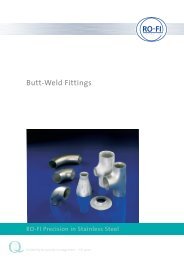
<strong>Butt</strong>-<strong>Weld</strong> <strong>Fittings</strong><br />
<strong>Fittings</strong> for welding DIN 2609<br />
11.2007_1.000<br />
Table 3. teat treating<br />
condition of delivery material group code<br />
normallized A to H N<br />
rather<br />
R to S<br />
transformed<br />
coated J, K, U V<br />
solution annealing L to Q L<br />
coated or normalized T V, N<br />
4.3 chemical composition<br />
At the chemical composition applies the, in the respective<br />
Norm<br />
of base material, denoted bounds for the ordered material.<br />
•• The product analysis which will be arranged at base material<br />
or at the fitting, can be agreed.<br />
4.4 mechanical properties<br />
The mechanical properties have to comply to the given values<br />
which are denoted in the appropriated norms of the base<br />
material (table 2). For the notched impact strength into the<br />
weld deposit applies the values of the base material across to<br />
the direction of rolling.<br />
4.5 weld ability<br />
Concerning to the weld ability you have to consider the details<br />
according to the norms of the base material (table 2).<br />
4.6 surface finish<br />
4.6.1 The fittings have to comply, to the way of manufacture, a<br />
smooth external and internal surface.<br />
4.6.2 Irregularities on the surface, conditional to the way of<br />
manufacture, like signs of indentations and elevations or flat<br />
grooves are marginal acceptable as far as the residual wall thickness<br />
complies to the requirements.<br />
4.6.3 The correct removal of surface defects with low-deepness<br />
is according to the application of suitable means acceptable as<br />
far as the residual wall thickness complies to the requirements.<br />
<strong>Weld</strong>ed corrections are just with the acceptance of the orderer<br />
acceptable.<br />
4.6.4 •• If you have special requirements concerning to the<br />
surface treatment, so you have to arrange it separately.<br />
4.7 measurement and measurement tolerances<br />
4.7.1 measurement<br />
For the measurement applies the details in the norms of measurement.<br />
4.7.2 measurement tolerances<br />
4.7.2.1 For the tolerances of construction dimensions and of the<br />
wall thickness under-usage applies the details in the norms of<br />
measurement.<br />
4.7.2.2 For the limiting sizes of external diameter at the pipe<br />
connection (at the weld seam) applies table 4 (of DIN<br />
1629/10.84, table 6).<br />
The upper limiting size of the wall thickness at the pipe connection<br />
(s, s1, s2) amounts to 15% of the nominal wall thickness for<br />
all nominal bores.<br />
4.7.2.3 For the safeguarding of throttling, the inner diameter will<br />
be restricted to the connecting tube. (comprised also the upper<br />
limiting sizes of wall thickness s3, s4, si and sa).<br />
The theoretic inner diameter of the tube will be calculated as the<br />
following.<br />
Theoretic inner diameter = da-2 ? nominal wall thickness (connection<br />
of wall thickness) [nominal bore diameter]<br />
4.7.2.4 For the circularity tolerance applies:<br />
a) on weld-end (weld-ends) of the fitting the table 4 (acc.<br />
DIN1626/10.84, table 6)<br />
b) for elbow according to the elbow length a difference of 4%.<br />
The balance R of the circularity will be calculate as follows:<br />
R = 200 • d a max --d a min<br />
in %<br />
d a max + d a min<br />
following is da maximal the biggest measured external diameter,<br />
da minimal the smallest measured external diameter (measured<br />
in the cross-section).<br />
4.7.2.5 For the meanderings of the fitting-geometry applies<br />
table 5 and the pictures 1-7. You have to measure at the orthographicaly<br />
together standing surfaces. The allowance Q may not<br />
exceed in any place at amount. It needs to keep all measurements<br />
of the fitting. At the inspection of the measurement Q<br />
you have to look for that the construction dimensions in the<br />
tolerances of the dimension standard will be complied. The<br />
Index at the dimensional letters Q in the pictures act up to the<br />
absolute measurement of the dimension standard after which<br />
you have to calculate the value Q.<br />
www.rofi.de<br />
Table 4. limiting sizes of external diameter and circularity tolerance<br />
external diameter limiting sizes of external diameter circularity tolerance<br />
d a<br />
•• at special<br />
mm<br />
decleration<br />
±1%d a<br />
inside by legal<br />
≤ 100 (±0,5 mm ±0,4 mm aperture<br />
allowed)<br />
allowance<br />
100 > d a ≤ 200 ±1%d a ±0,5%d a<br />
> 200 ±1%d a ±0,6%d a 2%<br />
<strong>RO</strong>-<strong>FI</strong> Precision in Stainless Steel<br />
4/5