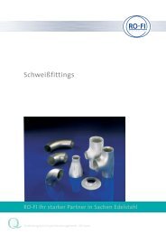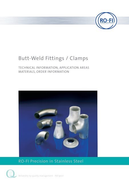
Butt-Weld Fittings / Clamps - RO-FI Edelstahl
Butt-Weld Fittings / Clamps - RO-FI Edelstahl
Butt-Weld Fittings / Clamps - RO-FI Edelstahl

You also want an ePaper? Increase the reach of your titles
YUMPU automatically turns print PDFs into web optimized ePapers that Google loves.
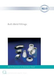
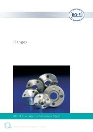
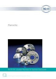
STAINLESS STEEL<br />
<strong>Butt</strong>-<strong>Weld</strong> <strong>Fittings</strong> / <strong>Clamps</strong><br />
TECHNICAL INFORMATION, APPLICATION AREAS<br />
MATERIALS, ORDER INFORMATION<br />
<strong>RO</strong>-<strong>FI</strong> Precision in Stainless Steel<br />
Zuverlässigkeit<br />
durch Qualitätsmanagement<br />
Reliability<br />
by quality<br />
management<br />
Reliability by quality management - ISO 9001
<strong>Butt</strong>-<strong>Weld</strong> <strong>Fittings</strong><br />
<strong>Fittings</strong> for welding DIN 2609<br />
Technical delivery conditions<br />
The with a point • signed sections contain details of declarations,<br />
which have to be mentioned<br />
in order. The with two points •• signed sections contain details<br />
about declarations, which are additional to the order.<br />
1 application area<br />
This norm is used for delivery of fittings acc. to DIN 2605 part 1<br />
and part 2, DIN 2615 part 1 and part 2 (currently concepts), DIN<br />
2616 part 1 and part 2 and DIN 2617 of unalloyed and alloyed<br />
steel. If the fittings get appliance into the application area of<br />
the order for control requiring special constructions according<br />
to § 24 of the trading regulations (for example steam boiler<br />
edict, pressure tank edict), you have to keep in mind the relevant<br />
technical rules (for example technical rules for steam boiler and<br />
technical rules for pressure tank).<br />
The same applies for other application areas, which exist for<br />
further instructions.<br />
Comment: You have to keep in your mind that total demands and<br />
reaction of scale which to act up in table 2, can reduce or raise the<br />
temperature limits.<br />
The fittings will be used for welding.<br />
11.2007_1.000<br />
2 Order<br />
The selection of order details must be commit by purchaser.<br />
•In the order you have to act up beside the standard description<br />
of detail dimension standard always the quantity required<br />
(quantities), the kind of certification and maybe the question for<br />
additional technical rules.<br />
•• Furthermore you can arrange more particulars in the order<br />
which are according to the two points signed chapters.<br />
3 Materials<br />
The materials you have to choose from table 2.<br />
•• If fittings of other materials will be produced as in table 2<br />
denoted, is this norm apply accordingly.<br />
The possible form of manufacture of base material are in<br />
groups of materials combined.<br />
The detail groups of materials have the nickname of the characterise<br />
material and a code letter for designation.<br />
Standards committee pipes, pipe connections and pipe lines in<br />
DIN German institute for standardization registered society.<br />
www.rofi.de<br />
<strong>RO</strong>-<strong>FI</strong> Precision in Stainless Steel<br />
4/1
<strong>Butt</strong>-<strong>Weld</strong> <strong>Fittings</strong><br />
<strong>Fittings</strong> for welding DIN 2609<br />
4 Requirements<br />
4.1 manufacturing process<br />
Being valid the manufacturing process according to table 1. The<br />
manufacturing process according to table 1 leave to the<br />
manufacturer. Purchaser has to be informed about it, on<br />
request.<br />
The manufacturing plant have to command by competent personal<br />
and adequate procedure, so that they can weld, deform<br />
and handle blameless to accomplish, supervising and check.<br />
•• If several manufacturing processes, form of base material<br />
and/or welding process get apart of, so it is necessary to agree.<br />
If it will be welded in production process of fittings, you have to<br />
comply the requirements to chapter 4.1.1 – 4.1.3, the principles<br />
and requirements of DIN 8563 part1 must be considered.<br />
4.1.1 You have to weld the fittings so that the weldseam is welded<br />
through and the fittings are according to the standard of<br />
this norm. The blameless accomplishment of welding is necessary<br />
to control.<br />
The fittings are effective for an internal pressure loading for a<br />
exploitation of the acceptable calculating range of 100%.<br />
•• The assessment group of the weld seam according to DIN<br />
8563 part 3 is to arrange especial between orderer and manufacturer.<br />
4.1.2 At Fusion-welded fittings the weldseam have to be welded<br />
of both sides as far as they are accessible from inside.<br />
A local correction of the weldseam is permitted. The orderer can<br />
ask for a throwaway evidence of the acceptability of the correction<br />
renovation according to article 4.1.3.<br />
The corrected parts have to undergone by a non-destructive<br />
test.<br />
4.1.3 •• Orderer can ask for a certificate about the discharge of<br />
the requirements according to article 4.1. The particulars about<br />
this certificate, especial about the test point, are arranging between<br />
the orderer and the manufacturer. This certificate are just<br />
considered for those steel grades, measure areas, welding processes<br />
and welding additions which get named to him.<br />
4.2 Condition of delivery<br />
4.2.1 Fabrication by cold forming<br />
By fittings which are made by cold forming you can abdicate the<br />
heat treating if the terms of the material characteristics according<br />
to the AD-leaflat HP 7/2 rather HP7/3 are discharged.<br />
•• If a heat treating is necessary, you have to deliver the fittings<br />
in the heat treatment according to table 3 as far as it is not<br />
denoted in the standards of the base material.<br />
4.2.2 Fabrication of hot forming<br />
You have to deliver the fittings in the heat treatment according to<br />
table 3 as far as in the standards of the base material nothing else<br />
is denoted. The account of a appropriated heat treatment in the<br />
group of materials A – H, L – S is fulfilled when material is in good<br />
order and condition and an adequate constancy by hot forming is<br />
secured. Considering to the same requirements by the group of<br />
materials J and K can comply an annealing instead of a complete<br />
recompense.<br />
11.2007_1.000<br />
Table 1. manufacturing process, allocated form of manufacture of base materials 1)<br />
manufacturing hot forming cold deformed to the manuf.<br />
process bended in the swake grinded, bended in the swake rolled 2) from solid<br />
compressed 2) forged and compressed 2) metal machin.<br />
machinabled<br />
arranged<br />
fitting arranged till DN 50<br />
bend 1, 2, 1, 2, 3, – 1, 2, 1, 2, 3, – –<br />
4, 5 4, 5 4, 5 4, 5<br />
T – 1, 2, 3, 4, 5 – 1, 2, 3, – –<br />
4, 5 4, 5<br />
reducer – 1, 2, 3, 4, 5 – 1, 2, 3, 1, 2, 3, 5<br />
4, 5 4, 5<br />
Cap – 1, 2, 3, 4, 5 – 1, 2, 3, 1, 2, 3, 5<br />
4, 5 4, 5<br />
1) Form of manufacture of base materials<br />
1 seamless tube<br />
2 welded tube (just tubes with a allowance calculation<br />
range of 100% in the weldseam)<br />
3 sheet<br />
4 forging<br />
5 bars<br />
2) At this manufacturing process can be welded too.<br />
4/2<br />
<strong>RO</strong>-<strong>FI</strong> Precision in Stainless Steel
<strong>Butt</strong>-<strong>Weld</strong> <strong>Fittings</strong><br />
<strong>Fittings</strong> for welding DIN 2609<br />
11.2007_1.000<br />
Table 2. base material, materials and form of manufacture<br />
group of materials base material material form of manufacture 1) base material application<br />
code- temperature *)<br />
letter nickname material Nr. 1 2 3 4 5 •C<br />
A St 37.0 St 37.0 1.0254 x DIN 1629 - 10 to 300<br />
St 37.0 1.0254 x DIN 1626<br />
RSt 37-2 1.0038 x x x DIN 17 100<br />
B St 44.0 St 44.0 1.0256 x DIN 1629 - 10 to 300<br />
St44.0 1.0256 x DIN 1626<br />
St 44-2 1.0044 x x x DIN 17 100<br />
C St 52.0 St 52.0 1.0421 x DIN 1629 - 10 to 300<br />
St 52.0 1.0421 x DIN 1626<br />
St 52-3 1.0570 x x x DIN 17 100<br />
D StE 290.7 StE 290.7 1.0484 x x DIN 17 172 - 10 to 50<br />
E StE 360.7 StE 360.7 1.0582 x x DIN 17 172 - 10 to 50<br />
F St 35.8 I St 35.8 I 1.0305 x DIN 17 175 - 10 to 420<br />
St 37.8 I 1.0315 x DIN 17 177<br />
H I 1.0345 x DIN 17 155<br />
H II 1.0425 x DIN 17 155<br />
C 22.8 1.0460 x x DIN 17 243<br />
G St 35.8 III St 35.8 III 1.0305 x DIN 17 175 - 10 to 420<br />
St 37.8 III 1.0315 x DIN 17 177<br />
H II 1.0425 x DIN 17 155<br />
C 22.8 1.0460 x x DIN 17 243<br />
H 15 Mo 3 15 Mo 3 1.5415 x DIN 17 175 - 10 to 530<br />
x DIN 17 177<br />
x DIN 17 155<br />
x x DIN 17 243<br />
J 13 CrMo 4 4 13 CrMo 44 1.7335 x DIN 17 175 - 10 to 570<br />
x DIN 17 155<br />
x x DIN 17 243<br />
K 10 CrMo 9 10 10 Cr Mo 9 10 1.7380 x DIN 17 175 - 10 to 600<br />
x DIN 17 155<br />
x x DIN 17 243<br />
L X 5 CrNi 18 11 X 5 CrNi 18 11 1.4301 x DIN 17 458 - 200 to 550 3)<br />
x DIN 17 457<br />
x x x DIN 17 440<br />
M X 2 CrNi 19 11 X 2 CrNi 19 11 1.4306 x DIN 17 458 - 200 5) to 550 3)<br />
x DIN 17 457<br />
x x x DIN 17 440<br />
N X 6 CrNiTi 18 10 X 6 CrNiTi 18 10 1.4541 x 2) DIN 17 458 - 200 5) to 550 3)<br />
x DIN 17 457<br />
x x x DIN 17 440<br />
O X 5 CrNiMo 17 12 2 X 5 CrNiMo 17 12 2 1.4401 x DIN 17 458 - 200 to 550 3)<br />
x DIN 17 457<br />
x x x DIN 17 440<br />
P X 2 CrNiMo 17 13 2 X 2 CrNiMo 17 13 2 1.4404 x DIN 17 458 - 200 to 550 3)<br />
x DIN 17 457<br />
x x x DIN 17 440<br />
Q X 6 CrNiMoTi 17 12 2 X 6 CrNiMoTi 17 12 2 1.4571 x 2) DIN 17 458 - 200 5) to 550 3)<br />
x DIN 17 457<br />
x x x DIN 17 440<br />
R WStE 355 WStE 355 1.0565 x DIN 17 179 - 20 to 400<br />
x DIN 17 178<br />
x x DIN 17 102<br />
x DIN 17 103<br />
www.rofi.de<br />
<strong>RO</strong>-<strong>FI</strong> Precision in Stainless Steel<br />
4/3
<strong>Butt</strong>-<strong>Weld</strong> <strong>Fittings</strong><br />
<strong>Fittings</strong> for welding DIN 2609<br />
Table 2. base material, materials and form of manufacture<br />
group of materials base material material form of manufacture 1) base material application<br />
code- temperature *)<br />
letter nickname material Nr. 1 2 3 4 5 •C<br />
S TStE 355 TStE 355 1.0566 x DIN 17 179 - 60 to 50 4)<br />
x DIN 17 178<br />
x x DIN 17 102<br />
x DIN 17 103<br />
T TStE 285 TStE 285 1.0566 x DIN 17 179 - 60 to 50 4)<br />
x DIN 17 178<br />
x x DIN 17 102<br />
x DIN 17 103<br />
U 10 Ni 14 10 Ni 14 1.5637 x DIN 17 173 - 105 to 50 4)<br />
x DIN 17 174<br />
x x x DIN 17 280<br />
*) Named values are cut-off values. For dimensioning use the in<br />
the material norm stipulated values.<br />
1) See table 1<br />
2) The details about the acceptable utilisation factor in the<br />
dimension standard just apply at application of cold manufactured<br />
tubes. If you use hot manufactured tubes you have<br />
to arrange it between orderer and manufacturer, because of<br />
the low resistance data.<br />
3) Until a temperature to 300°C (material group L,O) rather<br />
350°C (material group M) rather 400°C (group of tools N, P,Q)<br />
the material has not change so much that it at the check<br />
according to DIN 50914 shows susceptibility against inter crystalline<br />
corrosion .<br />
4) The indicated values can be overtaken for a temporary operation<br />
because at a long term application and at higher temperature<br />
can advocate a curtailing robustness attitude at lower<br />
temperatures.<br />
5) At application temperatures lower than -200°C till -270°C<br />
check of impact work at -196°C with ISOV samples, min.<br />
account 40J for wall thickness > 10mm, at bar material and<br />
forge material of bore > 15 mm<br />
11.2007_1.000<br />
4/4<br />
<strong>RO</strong>-<strong>FI</strong> Precision in Stainless Steel
<strong>Butt</strong>-<strong>Weld</strong> <strong>Fittings</strong><br />
<strong>Fittings</strong> for welding DIN 2609<br />
11.2007_1.000<br />
Table 3. teat treating<br />
condition of delivery material group code<br />
normallized A to H N<br />
rather<br />
R to S<br />
transformed<br />
coated J, K, U V<br />
solution annealing L to Q L<br />
coated or normalized T V, N<br />
4.3 chemical composition<br />
At the chemical composition applies the, in the respective<br />
Norm<br />
of base material, denoted bounds for the ordered material.<br />
•• The product analysis which will be arranged at base material<br />
or at the fitting, can be agreed.<br />
4.4 mechanical properties<br />
The mechanical properties have to comply to the given values<br />
which are denoted in the appropriated norms of the base<br />
material (table 2). For the notched impact strength into the<br />
weld deposit applies the values of the base material across to<br />
the direction of rolling.<br />
4.5 weld ability<br />
Concerning to the weld ability you have to consider the details<br />
according to the norms of the base material (table 2).<br />
4.6 surface finish<br />
4.6.1 The fittings have to comply, to the way of manufacture, a<br />
smooth external and internal surface.<br />
4.6.2 Irregularities on the surface, conditional to the way of<br />
manufacture, like signs of indentations and elevations or flat<br />
grooves are marginal acceptable as far as the residual wall thickness<br />
complies to the requirements.<br />
4.6.3 The correct removal of surface defects with low-deepness<br />
is according to the application of suitable means acceptable as<br />
far as the residual wall thickness complies to the requirements.<br />
<strong>Weld</strong>ed corrections are just with the acceptance of the orderer<br />
acceptable.<br />
4.6.4 •• If you have special requirements concerning to the<br />
surface treatment, so you have to arrange it separately.<br />
4.7 measurement and measurement tolerances<br />
4.7.1 measurement<br />
For the measurement applies the details in the norms of measurement.<br />
4.7.2 measurement tolerances<br />
4.7.2.1 For the tolerances of construction dimensions and of the<br />
wall thickness under-usage applies the details in the norms of<br />
measurement.<br />
4.7.2.2 For the limiting sizes of external diameter at the pipe<br />
connection (at the weld seam) applies table 4 (of DIN<br />
1629/10.84, table 6).<br />
The upper limiting size of the wall thickness at the pipe connection<br />
(s, s1, s2) amounts to 15% of the nominal wall thickness for<br />
all nominal bores.<br />
4.7.2.3 For the safeguarding of throttling, the inner diameter will<br />
be restricted to the connecting tube. (comprised also the upper<br />
limiting sizes of wall thickness s3, s4, si and sa).<br />
The theoretic inner diameter of the tube will be calculated as the<br />
following.<br />
Theoretic inner diameter = da-2 ? nominal wall thickness (connection<br />
of wall thickness) [nominal bore diameter]<br />
4.7.2.4 For the circularity tolerance applies:<br />
a) on weld-end (weld-ends) of the fitting the table 4 (acc.<br />
DIN1626/10.84, table 6)<br />
b) for elbow according to the elbow length a difference of 4%.<br />
The balance R of the circularity will be calculate as follows:<br />
R = 200 • d a max --d a min<br />
in %<br />
d a max + d a min<br />
following is da maximal the biggest measured external diameter,<br />
da minimal the smallest measured external diameter (measured<br />
in the cross-section).<br />
4.7.2.5 For the meanderings of the fitting-geometry applies<br />
table 5 and the pictures 1-7. You have to measure at the orthographicaly<br />
together standing surfaces. The allowance Q may not<br />
exceed in any place at amount. It needs to keep all measurements<br />
of the fitting. At the inspection of the measurement Q<br />
you have to look for that the construction dimensions in the<br />
tolerances of the dimension standard will be complied. The<br />
Index at the dimensional letters Q in the pictures act up to the<br />
absolute measurement of the dimension standard after which<br />
you have to calculate the value Q.<br />
www.rofi.de<br />
Table 4. limiting sizes of external diameter and circularity tolerance<br />
external diameter limiting sizes of external diameter circularity tolerance<br />
d a<br />
•• at special<br />
mm<br />
decleration<br />
±1%d a<br />
inside by legal<br />
≤ 100 (±0,5 mm ±0,4 mm aperture<br />
allowed)<br />
allowance<br />
100 > d a ≤ 200 ±1%d a ±0,5%d a<br />
> 200 ±1%d a ±0,6%d a 2%<br />
<strong>RO</strong>-<strong>FI</strong> Precision in Stainless Steel<br />
4/5
<strong>Butt</strong>-<strong>Weld</strong> <strong>Fittings</strong><br />
<strong>Fittings</strong> for welding DIN 2609<br />
Q da<br />
Q d a<br />
d<br />
b<br />
Q a<br />
2<br />
b<br />
2<br />
Q d a<br />
b<br />
2b<br />
picture 1 picture 2 picture 3<br />
Q d1<br />
t 1<br />
Q d 1<br />
b<br />
t 2<br />
d<br />
d 3 -<br />
1<br />
d 3<br />
d 3<br />
Q d 1<br />
l<br />
Q d 2<br />
Q d 1<br />
l<br />
Q d 2<br />
U 1<br />
U 2<br />
Q d1<br />
Q d1<br />
Q d1<br />
a a<br />
picture 4 picture 5 picture 6 picture 7<br />
dimensions e a, b, d a , d 1 , d 2 , l, t 1 , t 2 , u 1 und u 2 see norms of measurement<br />
Table 5. allowance Q<br />
•• standard design<br />
at special<br />
decleration<br />
4.7.3 wave formation at elbows<br />
Flat waves as in picture 8 are acceptable. The medium wave<br />
height hm may not exceed 3% of da1.<br />
h m = d a 2 + d a 4 – d a 3 (2)<br />
2<br />
where<br />
L ≥ 15 • h m (3)<br />
d a 1<br />
d a 2<br />
d a 3<br />
allowance Q<br />
1 % of basic dimension<br />
(1 mm allowed)<br />
0,5 % of basic dimension<br />
(0,5 mm allowed)<br />
L<br />
d a 4<br />
4.7.4 Accomplishment of the weldends<br />
Rule model of the edge form: ordered wall thickness of the weldends.<br />
till 3 mm face form DIN 2559–1<br />
above 3 mm till 16 mm face form DIN 2559–22<br />
above 16 mm face form DIN 2559–3<br />
•• Other face forms needs to be agreed.<br />
5 Checking and certification about<br />
material control<br />
5.1 Generel<br />
The fittings according to this norm can be delivered with one<br />
of the following certification about material control DIN EN<br />
10204.<br />
– Certification DIN 102 04 – 2.2<br />
– Certification DIN 102 04 – 3.1 A<br />
– Certification DIN 102 04 – 3.1 B<br />
– Certification DIN 102 04 – 3.1 C<br />
• The kind of the desired certification has to act up with the<br />
order.<br />
5.2 Location of checking<br />
The particles will be tested in the manufacturing plant. 5.3<br />
scope of inspection<br />
5.3 Scope of inspection<br />
5.3.1 At the certificate according to DIN EN10204, the values for<br />
the yield point, tensile strength and breaking elongation as far<br />
as the case may be the completion of the in chapter 5.4.3<br />
named requirements at the technological bending test due to<br />
the up on to the internal checking will be confirmed.<br />
The nominal width of the certified fittings have to comply to<br />
the presentable production program.<br />
11.2007_1.000<br />
4/6<br />
<strong>RO</strong>-<strong>FI</strong> Precision in Stainless Steel
<strong>Butt</strong>-<strong>Weld</strong> <strong>Fittings</strong><br />
<strong>Fittings</strong> for welding DIN 2609<br />
11.2007_1.000<br />
5.3.2 <strong>Fittings</strong> which are delivered with the certificate according<br />
to DIN 50049, will be tested in batches. An overview about the<br />
scope of inspection contains table 6.<br />
For the check, the fittings must be arranged according to material<br />
and measurement, at da > 100 mm of alloyed steels, and<br />
the same heat number in dependence of the external diameter<br />
da 1) in batches of the following quantities:<br />
d a < 100 mm . . . . . . . . . .500 pieces<br />
100 mm ≤ d a < 350 mm . . . . . . . . . .200 pieces<br />
d a > 350 mm . . . . . . . . . .100 pieces<br />
for elbows according to DIN 2605 part 1 and part 2 construction<br />
10 and 20 the maximal quantity per batch will be mottled.<br />
Remaining quantity up to 50% of the batch-size can share out<br />
equable of the detail batches. Quantities and remaining quantity<br />
over 50%, also delivery quantity of less than 50% of the<br />
batch-sizes, considered as one closed batch.<br />
For materials, which will undergo a heat treatment, the batch is<br />
bound to one heat treatment but for fittings with the same<br />
heat no. of unalloyed steel, which are apart got the same heat<br />
treatment can be checked together if the constancy of the components<br />
at a hardness test of 10% but minimal at 3 fittings,<br />
(according to the in the order specified certificate) are detected<br />
to the expert. The precondition of more evenly heat treatment<br />
deemed as fulfilled when the difference between the highest<br />
and the lowest measured hardness have not more than 30 HB<br />
5.3.3 For the accomplishment of the assay, for the class of material<br />
A-G and R-T at a test piece, for the class of material H-Q and<br />
U at two test pieces, you have to take one assay per batch after<br />
the last heat treatment. The checkout can result at the fittings<br />
themselves, at an overlength or at a trial example. Per measurement<br />
and material - for alloyed materials with da> 100 mm<br />
with the same<br />
melt also – at a closed delivery quantity will be tested maximal<br />
4 batches.<br />
5.3.4 At delivery quantities unto 10 of the same fittings, you<br />
have to take a test piece.<br />
5.3.5 At the test pieces will arrange the following assays will bes<br />
tested:<br />
– pull-out test at a room temperature for da> 100 mm.<br />
For fittings with da < 100 mm instead of the pull-out test a<br />
hardness test will be done at 10% of the pieces but at a minimum<br />
of 3 pieces.<br />
With the second batch of a closed delivery the scope of inspection<br />
for a hardness test can be mottled when the calculated values<br />
of the hardness are in the defined closeness<br />
range(reassessment according to Din 50150).<br />
– At fittings which are made by welding with da > 200 mm<br />
additional to a pull-out test across to the weld seam.<br />
– The impact bending test 2) accordant to the values in the<br />
norms of the base materials<br />
– Additional impact bending test in the middle of the weld<br />
seam at by welding manufactured fittings 2)<br />
at the class of material D, E, T and U for da > 200 mm and the<br />
nominal wall thickness > 5 mm,<br />
at class of material F – K for da >= 100 mm and a nominal wall<br />
thickness > 5 mm if a sampling of a non directional assay with a<br />
width of minimal 5 mm is possible.<br />
In class of materials R and S for da > 200 mm and a nominal<br />
wall thickness > 10 mm.<br />
In Class of materials L – Q for da >= 100 mm and a nominal wall<br />
thickness > 12 mm.<br />
– technological bending test at, by welding manufactured fittings.<br />
5.3.6 • • You have to agree in addition at the order:<br />
– The re examination of the chemical composite (product analysis).<br />
It will, per melting, be done at a test piece or at the base<br />
material.<br />
– Hot tensile test for da >= 100 mm, 1 test per batch. The test<br />
temperatures have to be arrange before 3).<br />
– Test of inter-crystalline corrosion . This test can only be done<br />
for the class of materials L – Q.<br />
5.3.7 Beyond that:<br />
– all fittings of alloyesteel have to undergo a test to exclude<br />
any chance of a material confusion<br />
– all fittings have to be controlled upon the look of the surface,<br />
internal and external<br />
– all fittings have to be confirmed in the compliance of the<br />
dimensions and tolerances of dimensions<br />
– all, by welding manufactured fittings, have to be controlled<br />
the weld-seam of a examination assay of steel-iron-test sheet<br />
1916.<br />
5.3.8 At the base material carried out ultrasonic and radiographic<br />
tests, for the raw material and the weld seam, don´t have<br />
to repeated at the fitting.<br />
5.3.9 •• An examination of the fittings can be agreed, but keep<br />
in mind that the fitting dimensions and the fitting forms can<br />
affect the test results.<br />
5.3.10 For the chemical analysis the manufacturer has to attest<br />
the correctness of the base material, the cast analysis per melt<br />
or casting device according to the in the base material defined<br />
values and variations.<br />
This attests can be take over for the certificate of the fittings<br />
1) look to table 6, gloss 7<br />
2) look to table 6, gloss 1<br />
3) look to table 6, gloss 2<br />
www.rofi.de<br />
<strong>RO</strong>-<strong>FI</strong> Precision in Stainless Steel<br />
4/7
<strong>Butt</strong>-<strong>Weld</strong> <strong>Fittings</strong><br />
<strong>Fittings</strong> for welding DIN 2609<br />
5.4 Sampling and sample preparation<br />
5.4.1 pull-out test<br />
For the pull-out test the fitting will undergo a tensile strength test<br />
lengthwise according to DIN 50125. The assay will not be heat treated<br />
and internally of the gauge length not adjusted.<br />
At fittings with a external diameter of da > 200 mm can – if the test<br />
pieces allow it without being adjusted- treated round- or flat specimen(look<br />
to DIN 50125), be removed as transverse test specimen.<br />
5.4.2 Beam impact test<br />
For the beam impact test at the fitting you take per fitting 1 set ISO-<br />
V-samples, in being of 2 specimen as transverse test specimen (if for<br />
the class of material F – K in the norms for the base material, according<br />
to table 2, not act up another specimen shape) when the fittings<br />
allow it without adjusting, otherwise you have to take longitudinal<br />
test specimen.<br />
For the beam impact test in the middle of the weldseam, you have<br />
to take from the fitting 1 set ISO-V-samples, across the weld seam,<br />
consisting of 3 specimen.<br />
You have to take the assays in a way that the notch axis lies vertically<br />
to the fitting surface and at the, in the weld seam to taking assays in<br />
the middle of the weld seam.<br />
5.4.3 Technological bending test<br />
For the technological bending test, for welded fittings produced<br />
from sheet, you take per batch 2 test fittings across to weldseam,<br />
with the weldseam in the middle. Here you have to consider the<br />
details accordimg DIN 50120 part 1.<br />
5.4.4 Chemical composition<br />
If the chemical composition as product analysis was not tested at<br />
base material, after the agreement of the norms of the base material,<br />
you have to take an assay at a test piece of the fitting according<br />
to the steel test specification 1805.<br />
5.5 Accomplishment of the assay<br />
5.5.1 The pull-out test at the fitting is to be arranged at the fitting<br />
according to DIN 50145. The pull-out test across the weldseam is<br />
arranged with assays according to DIN 50120 part 1/09.75, picture 1<br />
and DIN 50120 part 2/08.78, picture 2. If the certificate was agreed<br />
at 0,2%- 0,1%- of the creep limit with higher temperatures, it´s<br />
ascertain according to DIN 50145.<br />
5.5.2 The beam impact test is to be arranged according to DIN 50115,<br />
each at the for the concerning materials named lowest temperatures<br />
of norms from base material.<br />
5.5.3 The technological bending test, at by welding manufactured<br />
fittings, is to be arrange according to DIN 50121 part 1. An Assay is to<br />
be tested at the outside of the fitting and the other at the inside of<br />
the fitting in the tensile zone.<br />
5.5.4 The hardness test is to be arrange according to DIN 50351 once<br />
per each fitting.<br />
5.5.5 The examination of the weldseam is to be arrange according<br />
to the steel test specification 1916.<br />
For the non-destructive test of the fittings, consider the agreement<br />
of the steel test specification 1915 and/or 1918 and/or 1919.<br />
•• The inspection conditions of surface crack test according to the<br />
magnetic powder test or the test method of colour introducing<br />
have to be agreed.<br />
5.5.6 The look of the fittings is to be tested by an inspection with normal<br />
visual acuity and with adapted illumination.<br />
5.5.7 The dimensions of the fittings have to be tested with an adapted<br />
measuring instrument.<br />
5.6 Re-qualification<br />
For re-qualification consider DIN 17010.<br />
5.7 Certificate about material control<br />
5.7.1 For fittings without inspection a certificate will be exposed<br />
according to DIN 50049 – 2.2.<br />
5.7.2 4.1.1 For fittings with inspection will be exposed, depending on<br />
the agreement at the order (chapter 5.1) a certificate according to<br />
DIN EN 10204 3.1 or 3.2. The form and area of the assay, the competence<br />
for the accomplishment of the assays and the form the of the<br />
assay have to be considered, certificates are named in table 6.<br />
5.7.3 The identification according to chapter 6 must be obvious on<br />
certificate. To find the affiliation of the test result to the different<br />
deliveries and test units, all features of the certificates must be<br />
obvious.<br />
•• Details in the certificates about the manufacturing process and<br />
the heat treatment, at welded fittings additionally about the welding<br />
process and welding consumable have to be arranged separately.<br />
6 Marking<br />
The fittings have to be marked everlasting and clearly as the following:<br />
– sign of manufacturer<br />
– letter of the class of material and material short-name or number<br />
of base material (the details of the base material can drop<br />
to fittings with =
<strong>Butt</strong>-<strong>Weld</strong> <strong>Fittings</strong><br />
<strong>Fittings</strong> for welding DIN 2609<br />
11.2007_1.000<br />
Table 6. Schema about the scope of inspection and certificate about admeasurement assay at tittings with certificate.<br />
assay scope of inxpection for the proper form of<br />
accomplishment<br />
certificate about<br />
Nr Art chapter the assays material control<br />
1 cast analysis 4.3 per melt or casting device manufacture of DIN 10 204 – 2.2 4)<br />
the base material<br />
2 pull-out test at 5.3.5 per batch at two test pieces for the class of materials H – Q and U, at one by appointment DIN 10 204 – 3.1 A or<br />
room temperature test piece for class of materials A – G and R – T and at delivery quantity DIN 10 204 – 3.1 B or<br />
100mm.maximal 4 batches per delivery DIN 10 204 – 3.1 C<br />
quantity will be checked. At, by welding manufactured fittings, with da<br />
>200 additionally one assay across the weld seam.<br />
3 impact test 1) 5.3.5 per batch according to 2 of these table, 1 set >=3 single tests, according by appointment DIN 10 204 – 3.1 A or<br />
to the details in the norms of the base material for da>=100 mm.<br />
DIN 10 204 – 3.1 B or<br />
Additionally at by welding manufactured fittings 1 set = 3 single tests in<br />
DIN 10 204 – 3.1 C<br />
the middle of the weld seam.<br />
in class of material D,E,E,U from da> 200mm and wall thickness >=5mm<br />
in class of material F – K from da> 100mm and wall thickness >=5mm<br />
when the extraction of a omnidirectional assay with minimal 5 mm<br />
breadth is possible<br />
in class of material R,S from da> 200mm and wall thickness >=10mm<br />
in class of material L - Q from da> 100mm and wall thickness >=12mm<br />
4 technological 5.3.5 per batch at one test set by appointment DIN 10 204 – 3.1 A oder<br />
beam impact test 3)<br />
DIN 10 204 – 3.1 B oder<br />
DIN 10 204 – 3.1 C<br />
5 hot tensile 5.3.6 1 test pe-batch for d a ≥ 100 mm by appointment DIN 10 204 – 3.1 A oder<br />
test 5),2)<br />
DIN 10 204 – 3.1 B oder<br />
DIN 10 204 – 3.1 C<br />
6 examination 5.3.7 all fittings manufacturer DIN 10 204 – 3.1 B<br />
of the<br />
weld beam 3)<br />
7 spectro-chemical 5.3.7 all fittings of alloyed materials manufacturer DIN 10 204 – 2.1 4)<br />
analyis<br />
8 inspection 5.3.7 all fittings by appointment DIN 10 204 – 3.1 A oder<br />
DIN 10 204 – 3.1 B oder<br />
DIN 10 204 – 3.1 C<br />
9 dimensional 5.3.7 all fittings by appointment DIN 10 204 – 3.1 A oder<br />
check<br />
DIN 10 204 – 3.1 B oder<br />
DIN 10 204 – 3.1 C<br />
10 product analysis 5) 5.3.6 1 productanalysis per melting Manufacturer of the DIN 10 204 – 3.1 B<br />
material or<br />
the fittings<br />
11 examination 5.3.9 per melt by agreement manufacturer DIN 10 204 – 3.1 B<br />
of the base<br />
material 5)<br />
www.rofi.de<br />
12 assay of 5.3.6 according to agreement manufacturer DIN 10 204 – 3.1 B<br />
intercrystaline<br />
5), 6)<br />
corrosion<br />
13 hardness test 5.3.5 just at da
<strong>Butt</strong>-<strong>Weld</strong> <strong>Fittings</strong><br />
<strong>Fittings</strong> for welding DIN 2609<br />
Cited norms and other documents<br />
DIN 1626 <strong>Weld</strong>ed circularly tubes of unalloyed steels for special<br />
requirements; technical conditions of delivery<br />
DIN 1629 Seamless circularly tubes of unalloyed steels for<br />
special requirements; technical conditions of<br />
delivery<br />
DIN 2559 part 1 Preparation of the weld seam, guidelines for face<br />
form, melt welding of scarf joints at steel tubes<br />
DIN 2605 part 1 <strong>Fittings</strong> for welding, Elbows, reduced utilisation<br />
DIN 2605 part 2 <strong>Fittings</strong> tor welding, Elbows, full utilisation<br />
DIN 2615 part 1 <strong>Fittings</strong> for welding, Tees, reduced utalisation<br />
DIN 2615 part 2 <strong>Fittings</strong> tor welding, Tees, full utilisation<br />
DIN 2616 part 1 <strong>Fittings</strong> for welding, Reducer, reduced utilisation<br />
DIN 2616 part 2 <strong>Fittings</strong> for welding, Reducer, full utilisation<br />
DIN 2617 <strong>Fittings</strong> for welding, caps<br />
DIN 8563 part 1 Safeguarding of quality from welding, general<br />
fundamentals<br />
DIN 8563 part 2 Safeguarding of quality from welding, requirements<br />
of the company<br />
DIN 8563 part 3 Safeguarding of quality from welding, fusion<br />
welded joint at steel (unless steel welding), requirements,<br />
assessment group<br />
DIN 17010 General technical conditions of delivery for steel and<br />
steel products<br />
DIN 17100 General steel, quality standard<br />
DIN 17102 Fine grained steel which is able to weld, normalized,<br />
technical conditions of delivery for sheet, band steel,<br />
wide flat steel, sections and bars<br />
DIN 17103 Forgings of fine grained steel which is able to weld,<br />
technical conditions of delivery<br />
DIN 17155 Sheets and bands of heat resisting steels, technical<br />
conditions of delivery<br />
DIN 17172 Steel tubes for pipelines for flammable fluid and<br />
gases, technical conditions of delivery<br />
DIN 17173 Seamless circularly tubes of low-temperature steels,<br />
technical conditions of delivery<br />
DIN 17174 Seamless circularly tubes of heat resisting steels,<br />
technical conditions of delivery<br />
DIN 17175 Seamless tubes of heat resisting steels, technical<br />
conditions of delivery<br />
DIN 17177 Electrical pressure-welded tubes of heat resisting<br />
steels, technical conditions of delivery<br />
DIN 17178 <strong>Weld</strong>ed circularity tubes of fine grained steels for<br />
special requirements, technical conditions of delivery<br />
DIN 17179 Seamless circularity circularity tubes of fine grained<br />
steels for special requirements, technical conditions<br />
of delivery<br />
DIN 17243 Forgings and rolled and forged bars of heat resisting<br />
steels which is able to weld, technical conditions of<br />
delivery<br />
DIN 17280 Low-temperature steels, technical conditions of<br />
delivery for sheets, band steel, wide flat steel,<br />
sections, bars and forgings<br />
DIN 17440 Non-rusting steels, technical conditions of delivery<br />
for sheets, hot rolled strip, wire rod, drawn wire, bars,<br />
forgings and half finished products<br />
DIN 17457 <strong>Weld</strong>ed circularly tubes of austenitic stainless steels<br />
for special requirements, technical conditions of<br />
delivery<br />
DIN 17458 Seamless circularly tubes of austenitic stainless<br />
steel steels for special requirements, technical<br />
conditions of delivery<br />
DIN 10204 Certificate of material control<br />
DIN 50115 Assay of metallic materials, beam impact test<br />
DIN 50120 part 1 Assay of steel, pull-out test at welded connections,<br />
melt welded butt joints<br />
DIN 50120 part 2 Assay of steel, pull-out test at welded connections,<br />
pressure welded butt joints<br />
DIN 501121 part1 Assay of metallic materials, technical pull-out test at<br />
welded connections and welded plating, melt<br />
welded connections<br />
DIN 50125 Assay of metallic materials, tensile specimen<br />
DIN 50145 Assay of metallic materials, pull-out test<br />
DIN50150 Assay of steels and cast steel, table of reassessment<br />
for Vickers hardness, Brinell hardness, Rockwell<br />
hardness and tensile strength<br />
DIN 50351 Assay of metallic materials, hardness test according<br />
Brinell<br />
DIN 50914 Assay of non-rusting steels of consistency forward<br />
inter-crystalline corrosion, copper sulphatesulphuric<br />
mode, Strauß-test<br />
AD-data sheat HP7/2 *) heat treatment, ferritic steels<br />
AD-Merkblatt HP7/3 *) heat treatment, austenitic steels<br />
Steel test specification 1805 **) sampling and sample preparation for<br />
product analysis of steels<br />
Steel test specification 1915 **) ultrasonic test of longitudinal imperfection<br />
of tubes at heat resisting steels<br />
Steel test specification 1916 **) non-destructive test of melt welded<br />
pipelines for flammable fluids and gases<br />
Steel test specification 1918 **) ultrasonic test of transverse defect of<br />
tubes of heat resisting steels<br />
Steel test specification 1919 **) ultrasonic test of lamination at tubes<br />
of heat resisting steels<br />
Technical rules pressure tank (TRB) *)<br />
Technical rules for steam boiler (TRD) *)<br />
Establishment about pressure tank, compressed gas container and<br />
charging annex<br />
(Pressure tank establishment and general administrative instructions*)<br />
Establishment about steam boiler constructions (steam boiler establishment<br />
) and general administrative instructions *)<br />
International patent classification<br />
B 23 K<br />
F 16 L 43/00 F<br />
16 S 1/00<br />
*) To referring by: Beuth Verlag GmbH/ Berlin<br />
**) To referring by: Verlag Stahleisen mbH/Düsseldorf<br />
11.2007_1.000<br />
4/10<br />
<strong>RO</strong>-<strong>FI</strong> Precision in Stainless Steel
<strong>Butt</strong>-<strong>Weld</strong> <strong>Fittings</strong><br />
Caps DIN 2617<br />
measures in mm<br />
1 Coverage<br />
This norm consider for caps of steel which resist to the<br />
same internal pressure like the welded tube with a wall<br />
thickness s1 according to table 1 (see chapter 5 – basics of<br />
the calculation). The caps will be used as fittings to weld in.<br />
2 Type of design, description<br />
curved part<br />
cylindrical arrection<br />
11.2007_1.000<br />
Denotation of a cap according to this norm of a external<br />
diameter da = 88,9 mm and a wall thickness s1 = 2,3 mm,<br />
at a material of the material group C according to DIN<br />
2609:<br />
Cap DIN 2617 – 88,9 x 2,3 – C<br />
4/30<br />
<strong>RO</strong>-<strong>FI</strong> Precision in Stainless Steel
<strong>Butt</strong>-<strong>Weld</strong> <strong>Fittings</strong><br />
Caps DIN 2617<br />
11.2007_1.000<br />
3 dimensions Table 1.<br />
nom.- external wall thickness s 1, s 2 height limited wall<br />
width diameter line h thickness<br />
DN d a 1 2 3 4 5 s 1 ≤ limited s 1 > limited for height<br />
1)<br />
s 1<br />
2)<br />
s 2<br />
1)<br />
s 1<br />
1)<br />
s 1<br />
1)<br />
s 1<br />
1)<br />
s 1 wall thickn. wall thickn. h<br />
15 21,3 1,6 – – 2,0 3,2 4,0 25 25 –<br />
20 26,9 1,6 – – 2,3 3,2 4,0 25 25 –<br />
25 33,7 2,0 – – 2,6 3,2 4,0 38 38 –<br />
32 42,4 2,0 – – 2,6 3,6 4,0 38 38 –<br />
40 48,3 2,0 – – 2,6 4,0 5,0 38 38 –<br />
50 60,3 2,0 – – 2,9 4,5 5,6 38 38 –<br />
65 76,1 2,3 – – 2,9 5,0 7,1 38 38 –<br />
80 88,9 2,3 – – 3,2 5,6 8,0 51 51 –<br />
100 114,3 2,6 – – 3,6 6,3 8,8 64 64 –<br />
125 139,7 2,6 – – 4,0 6,3 10,0 76 76 –<br />
150 168,3 2,6 – 4,0 4,5 7,1 11,0 89 89 –<br />
200 219,1 2,9 – 4,5 6,3 8,0 12,5 102 102 –<br />
250 273,0 2,9 – 5,0 6,3 8,8 14,2 127 127 –<br />
300 323,9 2,9 3,0 5,6 7,1 10,0 16,0 152 152 –<br />
350 355,6 3,2 3,3 5,6 8,0 11,0 17,5 165 165 –<br />
400 406,4 3,2 3,4 6,3 8,8 12,5 20,0 178 178 –<br />
450 457,0 4,0 4,1 6,3 10,0 14,2 22,2 203 203 –<br />
500 508,0 4,0 4,2 6,3 11,0 16,0 25,0 229 229 –<br />
600 610,0 5,0 5,1 6,3 12,5 17,5 30,0 267 267 –<br />
700 711,0 5,0 5,3 7,1 12,5 20,0 32,0 267 290 25,0<br />
800 813,0 5,6 5,9 8,0 12,5 22,5 36,0 267 330 17,5<br />
900 914,0 6,3 6,7 10,0 12,5 25,0 40,0 267 370 10,0<br />
1000 1016,0 6,3 7,0 10,0 12,5 28,0 45,0 305 420 14,2<br />
1200 1220,0 6,3 7,2 12,5 – – – 343 360 10,0<br />
A line in the column s1 means that this wall thickness is not<br />
normed.<br />
1) s 2 ≥ s 1 (see gloss 2)<br />
2) In rank 1 of the wall thickness the nominal width DN 300 till<br />
DN 1200 the wall thickness s2 have to comply minimal at<br />
the in the column s2 named values.<br />
4 Acceptable dimension variations<br />
Table 2. lower limiting-sizes of the wall thickness<br />
(upper limiting-size see DIN 2609)<br />
nominal width wall thickness lower<br />
DN<br />
limiting-size<br />
≤ 600 all -12,5 %<br />
> 600 ≤ 10,0 -0,35 mm<br />
> 10,0 -0,50 mm<br />
5 Backgrounds of the calculation<br />
The wall thickness s2 is according to AD-leaflet B3 so calculated<br />
that the caps resist to the same internal pressure like<br />
the to welding tube with a wall thickness s1 according to<br />
table 1. The headroom h contains a cylindrical accretion of<br />
minimal 3 x s1. The calculation results towards the internal<br />
pressure with following assumptions:<br />
- lower limiting-size for tubes and caps according to table 2<br />
- same material<br />
- same longitudinal seam welding factor<br />
- same external diameter<br />
- without corrosion allowance<br />
- Utilisation of the tube = 100%<br />
www.rofi.de<br />
Table 3. limiting-sizes of the dimensions l 1<br />
nominal width<br />
limiting-size<br />
DN<br />
h<br />
15 to 100 ± 4<br />
125 to 600 ± 7<br />
700 to 1000 ± 10<br />
6 Differing wall thickness<br />
Caps with a wall thickness which are between the wall<br />
thickness of table 1 can also be order to the agreement of<br />
this norm.<br />
<strong>RO</strong>-<strong>FI</strong> Precision in Stainless Steel<br />
4/31
<strong>Butt</strong>-<strong>Weld</strong> <strong>Fittings</strong><br />
Curved heads DIN 28011/cap form<br />
measure in mm<br />
1 Coverage<br />
This norm is to use for curved heads in cap form (bumped<br />
boiler heads) with following connections:<br />
r 1 =d a r 2 =0,1d a h 1 ≥ 3,5 s 1) h 2 =0,1935d a -0,455s<br />
This norm consider for one piece heads with and without<br />
weld seam with a external diameter da=>4000 mm and<br />
a wall thickness s =< 50 mm.<br />
#For heads in larger dimensional range consider analogously<br />
the Scope of this norm, at which the tolerance -<br />
especially at heads of sections- have to arrange extra.<br />
Curved heads, elliptical head see DIN 28013.<br />
The calculation of the necessary wall thickness results for<br />
example:<br />
- for pressure tanks according to the technical rules of<br />
pressure tanks (TRB, AD-leaflets)<br />
- for steam boilers according to the technical rules of<br />
steam boilers (TRD)<br />
2 Type of design, description<br />
2.1 Geometrical connections<br />
11.2007_1.000<br />
curved part<br />
picture 1<br />
s = wall thickness, see Section 3.4.5<br />
Capacity of the curved part (without boarding height h1) V ≈ 0,1 (d a - 2s) 3<br />
2<br />
External surface of the curved part (without boarding height h1) A a ≈ 0,99 • d a<br />
Internal surface of the curved part (without boarding height h1) A i ≈ 0,99 • (d a - 2s) 2<br />
Reference line will be measured out of the finished kerb with h1 according to table 1<br />
At the order the designation of the reference line can be arrange.<br />
4/32<br />
<strong>RO</strong>-<strong>FI</strong> Precision in Stainless Steel
<strong>Butt</strong>-<strong>Weld</strong> <strong>Fittings</strong><br />
Curved heads DIN 28011/cap form<br />
Table 1.<br />
wall thickness<br />
height<br />
weight<br />
11.2007_1.000<br />
www.rofi.de<br />
• external diameter of the tube of the line 1 according to DIN 2448<br />
1) The height of the cylindrical collar at caps averages h1= 4000 mm the values have<br />
to calculate according to chapter 1 and 2<br />
<strong>RO</strong>-<strong>FI</strong> Precision in Stainless Steel<br />
4/33
<strong>Butt</strong>-<strong>Weld</strong> <strong>Fittings</strong><br />
Curved heads DIN 28011/cap form<br />
2.2 Angles<br />
form R form I form VA form VI form DV<br />
(as yet IR) (as yet IP) (as yet XS)<br />
I-seam V-seam V-seam DV-seam<br />
raw plan outside inside (symmetrical)<br />
form 2/3 DV form YA form YI form DY form U<br />
(as yet XA) (as yet YD) (as yet US)<br />
2/3-DV-seam Y-seam Y-seam double Y-seam U-seam<br />
(asymmetrical) outside inside (bevel) bell seam<br />
form DU form BI form BA<br />
(as yet ID) refilling refilling<br />
double-U-seam inside outside<br />
11.2007_1.000<br />
picture 2<br />
Processing of the angles mechanical or by flame cut. The dimensions<br />
c, f and x have to arrange at the order, also the angle and<br />
radii as far as they don´t comply to picture 2. Other preparation<br />
for the weldseam have to arrange with outlines at the order.<br />
2.3 Description<br />
Description of a cap with a external diameter da= 600 mm and<br />
wall thickness s= 20 mm with a angle form VA of steel HII according<br />
to DIN 17155:<br />
head DIN 28011 – 600 x 20 – VA – HII<br />
Description of a cap with a external diameter da= 600 mm and<br />
a minimal wall thickness smin= 19,5 mm with the angle form<br />
VA and BI with x = 15 mm of the steel breed HII according to<br />
DIN 17155:<br />
head DIN 28011 – 600 x 219,5 MIN – VA BI – 15 HII<br />
3 Technical conditions of delivery<br />
3.1 material<br />
As material can be arrange:<br />
- hot-rolled products of unalloyed steels according to DIN EN<br />
10025<br />
- heat resisting steels according to DIN 17155<br />
- non-rusting steels according to DIN 17440 or to the steel<br />
test specification 400<br />
- fine grain steel which is able to weld according to DIN 17102<br />
- low-temperature stells<br />
- plated steels according to the DIN norms,<br />
- high heat resisting and AD-leaflet, VdTÜV-material<br />
heat resisting steels<br />
sheet, steel test specification<br />
- special alloys<br />
- non-ferrous metals<br />
- materials according to other national and international regulations<br />
4/34<br />
<strong>RO</strong>-<strong>FI</strong> Precision in Stainless Steel
<strong>Butt</strong>-<strong>Weld</strong> <strong>Fittings</strong><br />
Curved heads DIN 28011/cap form<br />
3.2 Manufacturing and heat treatment<br />
The heads will be hot or cold formed according to the<br />
choice of the manufacturer if the kind of the form was<br />
not arrange before. The heat treatment have to arrange,<br />
for example according to the AD-leaflet of the line HP7.<br />
The manufacturer have to indicate if a head will be<br />
manufactured of several parts (before or after forming).<br />
3.3 Surface Condition<br />
Floors are supplied with untreated surface. Other surface<br />
conditions, such as descaled, pickled, blasted, are to be<br />
agreed.<br />
This height dimensions consider for heads with arranged<br />
kerbs. At heads with crude kerbs (form R) the hight h3 have<br />
to measured so that later all other forms of this norm have<br />
to be manufactured.<br />
3.4.2 Limiting-size for the ad-measurement<br />
Limiting-sizes for the ad-measurement are arranged in<br />
table 2.<br />
11.2007_1.000<br />
3.4 Limiting sizes<br />
3.4.1 Limiting sizes for the internal height h3<br />
For the height h3 = h1 + h2 the limiting sizes are:<br />
a) the upper dimension : + 0,015 da or +10 mm<br />
b) lower dimension: O<br />
Table 2. Lower limiting-sizes of the wall thickness<br />
(upper limiting-size see DIN 2609)<br />
material da limiting-size for<br />
the admeasurement<br />
Hot-rolled unalloyed steels d a < 100 ± 3,0 mm<br />
Heat resisting steels 100 ≤ d a < 300 ± 4,0 mm<br />
Low temperature steel 300 ≤ d a < 1000 ± 0,4 %<br />
(ferritic untempered) 1000 ≤ d a ≤ 4000 ± 0,3 %<br />
Fine grained steel<br />
Non-rusting steels d a < 100 ± 3,0 mm<br />
Superalloyed steels 100 ≤ d a < 300 ± 5,0 mm<br />
Low temperature steels 300 ≤ d a ≤ 4000 + 0,5 %<br />
(austenitic or tempered) –0,7%<br />
Austenitic plated steels<br />
Plated steels d a < 100 ± 3,0 mm<br />
besides austenitic plated steels 100 ≤ d a < 300 ± 5,0 mm<br />
Nonferrous metals 300 ≤ d a ≤ 4000 ± 1,0 %<br />
www.rofi.de<br />
3.4.3 Limiting-sizes for the non-cirularity u<br />
The non-cirularity u = 2 (d amax-da min)<br />
(damax-d a min )<br />
• 100 in % may just have 1 % maximum;<br />
also may the biggest diameter difference d a max – d a
<strong>Butt</strong>-<strong>Weld</strong> <strong>Fittings</strong><br />
Curved heads DIN 28011/cap form<br />
3.4.4 Restriction of the tolerances<br />
Lower limiting-sizes for the ad-measurement or the noncirularity<br />
tolerances have to be agree in special case. The<br />
limiting-sizes have to be agree if the caps should be used<br />
in pairs or as internal or external caps.<br />
3.4.5 Limiting-sizes for the wall-thickness<br />
For the limiting-sizes of the wall thickness consider:<br />
If at the order just the wall thickness is given, it can be fall<br />
below as in table 3.<br />
Table 3.<br />
wall thickness<br />
lower measure<br />
≤10 - 0,3<br />
> 10 ≤ 30 - 0,5<br />
> 30 ≤ 50 - 0,8<br />
> 50 - 1,0<br />
If in the order the minimum wall thickness is required, it<br />
doesn´t may fall below.<br />
(For the boarding height h1 in such cases consider instead<br />
of the wall thickness s the minimum wall thickness s min.<br />
For s min consider the value without decimal places).<br />
For the compliance of the required wall thickness or rather<br />
minimum wall thickness because of the production<br />
causes you have to provide that the accordant thickness<br />
surcharges for the slug of the sheet. Beyond that is a bigger<br />
wall thickness, especially in the area of the cylindrical<br />
board (compression) possible. A refilling has to act up in<br />
the order (form BI or BA according to chapter 2.2)<br />
3.5 Appointment of ad-measurement<br />
3.5.1 Position for the appointment of ad-measurement<br />
a) At heads with arranged kerbs at the border<br />
b) At heads with crude kerbs at the area between upper<br />
and lower limiting size of h3 of the height-related tolerance,<br />
according to chapter 3.4.1.<br />
3.5.2 Appointment of the external ad-measurement<br />
With calibrated measuring strip according to DIN 6409,<br />
the ad-measurement will be measured at the in chapter<br />
3.5.1 denoted area. At the calculation of the diameter you<br />
have to locate with 3,14159.<br />
3.5.3 Appointment of the internal ad-measurement<br />
a) ) Measuring of the external ad-measurement how described<br />
in chapter 3.5.2, less of the middle wall thickness<br />
which will be appoint of the arithmetical media of the<br />
ad-measurement of the wall thickness at the place of<br />
the measuring of the amount but at minimal 3 points<br />
and at heads with d a > 500 mm all 500 mm or<br />
b) with calibrated rolling dimension.<br />
3.6 Flattening<br />
At the area of the diameter r1 are flattening of the meridian<br />
circle acceptable (at flat areas measured by siting of<br />
a lineal) which has a length of maximal 15% of the diameter<br />
r 1 .<br />
3.7 Skewing of the cylindrical board<br />
widened head<br />
inverted head<br />
11.2007_1.000<br />
Bild 3<br />
4/36<br />
<strong>RO</strong>-<strong>FI</strong> Precision in Stainless Steel
<strong>Butt</strong>-<strong>Weld</strong> <strong>Fittings</strong><br />
Curved heads DIN 28011/cap form<br />
Limiting sizes of the right angle of the cylindrical board<br />
AD-leaflet line HP7 *)<br />
see table 4.<br />
VdTÜV-material-sheet *)*)<br />
Table 4.<br />
da<br />
< 1000 ≤ 4° ≤ 2°<br />
≥ 1000 ≤ 5° ≤ 2°<br />
Steel test specifications (SEW) ****)<br />
Technical rules pressure tank (TRB) ***)<br />
Technical rules steam boiler (TRD) *)<br />
Earlier editions<br />
At the arbitration the measurement has to accomplish<br />
DIN 28012: 10.70<br />
internal (compression).<br />
DIN 28011: 10.70, 05.87<br />
11.2007_1.000<br />
3.8 Certifications<br />
The necessary certifications have to a arrange at the<br />
order, for example according to the technical rules of<br />
pressure tank (TRB), technical rules of steam boiler (TRD).<br />
Cited norms and other documents<br />
DIN 2448<br />
Seamless steel tubes, dimensions,<br />
fibre coarseness<br />
DIN 6403<br />
Measuring tapes of steel<br />
DIN 17102<br />
Fine grained steel which is able to<br />
weld, normal annealed, technical<br />
conditions of delivery for sheet-,<br />
Modifications<br />
Compared to edition in may 1987 were changed:<br />
a) Changed nominal width in the wall thickness s and<br />
second example of appellation for the indication of the<br />
minimum wall thickness s min<br />
b) Changed capacity in volume<br />
c) Overworked editorial and technical standardisation<br />
International patent classification<br />
B 01 J 3/04<br />
B 65 D 90/02<br />
F 22 B 37/22<br />
F 16 J 12/00<br />
www.rofi.de<br />
stripe-, wide-flat-, form- and bar steel<br />
DIN 17155<br />
Sheet and stripe of heat resistant<br />
steels, technical conditions of delivery<br />
DIN 17440<br />
Non rusting steels, technical conditions<br />
of delivery for sheet, hot rolled<br />
stripe, wire rod, drawn wire, bar steel,<br />
forgings and half finished products<br />
DIN 28013<br />
Arced heads, elliptical head<br />
DIN EN 10025<br />
Hot rolled products of unalloyed<br />
steels, technical conditions of delivery,<br />
German version EN 100025: 1990<br />
<strong>RO</strong>-<strong>FI</strong> Precision in Stainless Steel<br />
4/37
STAINLESS STEEL<br />
www.rofi.de<br />
STAINLESS STEEL<br />
www.rofi.de<br />
South<br />
Karl-Arnold-Straße 7<br />
D-73230 Kirchheim/Teck<br />
Tel. +49 (0) 70 21 94 35-0<br />
Fax +49 (0) 70 21 5 60 31<br />
kirchheim@rofi.de<br />
North South Export<br />
Mittelgönrather Karl-Arnold-Straße Straße 7 15<br />
D-42655 D-73230 Solingen Kirchheim/Teck<br />
Tel. +49 (0) 2701212 94 3235-0<br />
54-0<br />
Fax +49 (0) 2701212 5326054-11<br />
31<br />
solingen@rofi.de<br />
kirchheim@rofi.de<br />
Middle North Export<br />
Ostendstraße Mittelgönrather 3 Straße 15<br />
D-63110 D-42655 Rodgau-Niederroden<br />
Solingen<br />
Tel. +49 (0) 61 2 12062 2328554-0<br />
79-30<br />
Fax +49 (0) 61 2 12062 232254-11<br />
08<br />
rodgau@rofi.de<br />
solingen@rofi.de<br />
East Middle<br />
Reuterstraße Ostendstraße 23<br />
D-99867 D-63110 Gotha Rodgau-Niederroden<br />
Tel. +49 (0) 36 61 21 06 72 33 85 97-0 79-30<br />
Fax +49 (0) 36 61 21 06 72 33 22 97-10 08<br />
gotha@rofi.de<br />
rodgau@rofi.de<br />
<strong>RO</strong>-<strong>FI</strong> Precision in Stainless Steel<br />
Zuverlässigkeit<br />
durch Qualitätsmanagement<br />
Reliability<br />
by quality<br />
management<br />
Reliability by quality management - ISO 9001<br />
East<br />
Reuterstraße 2<br />
D-99867 Gotha<br />
Tel. +49 (0) 36 21 7 33 97-0<br />
Fax +49 (0) 36 21 7 33 97-10<br />
gotha@rofi.de