C7005A,B Gas Pilot Flame Rod Assemblies - PexSupply.com
C7005A,B Gas Pilot Flame Rod Assemblies - PexSupply.com
C7005A,B Gas Pilot Flame Rod Assemblies - PexSupply.com

Create successful ePaper yourself
Turn your PDF publications into a flip-book with our unique Google optimized e-Paper software.
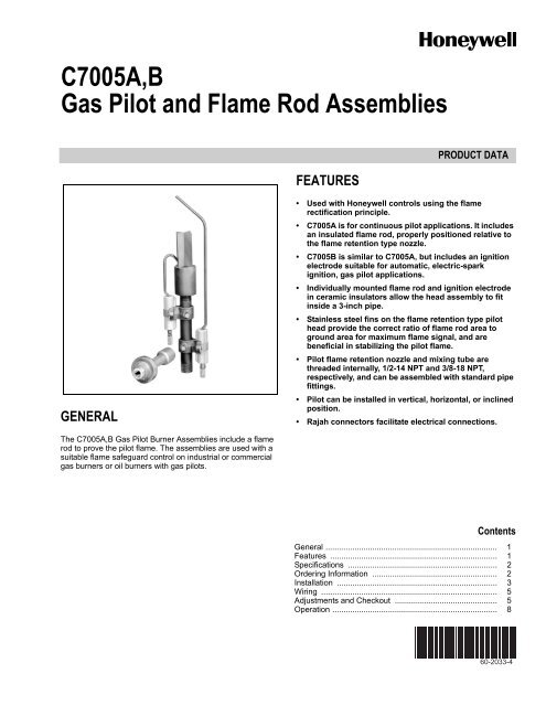
<strong>C7005A</strong>,B<br />
<strong>Gas</strong> <strong>Pilot</strong> and <strong>Flame</strong> <strong>Rod</strong> <strong>Assemblies</strong><br />
FEATURES<br />
PRODUCT DATA<br />
GENERAL<br />
• Used with Honeywell controls using the flame<br />
rectification principle.<br />
• <strong>C7005A</strong> is for continuous pilot applications. It includes<br />
an insulated flame rod, properly positioned relative to<br />
the flame retention type nozzle.<br />
• C7005B is similar to <strong>C7005A</strong>, but includes an ignition<br />
electrode suitable for automatic, electric-spark<br />
ignition, gas pilot applications.<br />
• Individually mounted flame rod and ignition electrode<br />
in ceramic insulators allow the head assembly to fit<br />
inside a 3-inch pipe.<br />
• Stainless steel fins on the flame retention type pilot<br />
head provide the correct ratio of flame rod area to<br />
ground area for maximum flame signal, and are<br />
beneficial in stabilizing the pilot flame.<br />
• <strong>Pilot</strong> flame retention nozzle and mixing tube are<br />
threaded internally, 1/2-14 NPT and 3/8-18 NPT,<br />
respectively, and can be assembled with standard pipe<br />
fittings.<br />
• <strong>Pilot</strong> can be installed in vertical, horizontal, or inclined<br />
position.<br />
• Rajah connectors facilitate electrical connections.<br />
The <strong>C7005A</strong>,B <strong>Gas</strong> <strong>Pilot</strong> Burner <strong>Assemblies</strong> include a flame<br />
rod to prove the pilot flame. The assemblies are used with a<br />
suitable flame safeguard control on industrial or <strong>com</strong>mercial<br />
gas burners or oil burners with gas pilots.<br />
Contents<br />
General ............................................................................. 1<br />
Features ........................................................................... 1<br />
Specifications ................................................................... 2<br />
Ordering Information ........................................................ 2<br />
Installation ........................................................................ 3<br />
Wiring ............................................................................... 5<br />
Adjustments and Checkout .............................................. 5<br />
Operation .......................................................................... 8<br />
60-2033-4
<strong>C7005A</strong>,B GAS PILOT AND FLAME ROD ASSEMBLIES<br />
SPECIFICATIONS<br />
IMPORTANT<br />
The specifications given in this publication do not<br />
include normal manufacturing tolerances. Therefore,<br />
this unit may not exactly match the listed specifications.<br />
Also, this product is tested and calibrated<br />
under closely controlled conditions, and some differences<br />
in performance can be expected if those conditions<br />
are changed.<br />
Models:<br />
<strong>C7005A</strong> <strong>Gas</strong> <strong>Pilot</strong> and <strong>Flame</strong> <strong>Rod</strong> Assembly—for continuous<br />
pilot applications; includes flame rod only.<br />
C7005B <strong>Gas</strong> <strong>Pilot</strong> and <strong>Flame</strong> <strong>Rod</strong> Assembly—for automatic<br />
pilot applications; includes flame rod and ignition<br />
electrode.<br />
<strong>Pilot</strong> Head:<br />
<strong>Flame</strong> retention type with stainless steel bomb type fins.<br />
Threaded onto 1/2 x 6 inch (152 mm) pipe nipple with<br />
1/2-14 NPT external threads.<br />
Type of <strong>Gas</strong>:<br />
Models available for use with natural and propane gases.<br />
<strong>Gas</strong> Capacity (Varies with <strong>Gas</strong> Pressure):<br />
<strong>Gas</strong> Pressure<br />
in. wc<br />
Capacity<br />
kPa ft 3 /hr m 3 /hr<br />
3 0.75 12.0 0.34<br />
4 0.99 13.7 0.39<br />
5 1.24 15.3 0.43<br />
6 1.49 16.8 0.48<br />
7 1.74 18.2 0.52<br />
<strong>Flame</strong> <strong>Rod</strong>/Ignition Electrode Insulators:<br />
Ceramic.<br />
Maximum Temperature at <strong>Flame</strong> <strong>Rod</strong> Insulator:<br />
500°F (260°C).<br />
<strong>Flame</strong> <strong>Rod</strong>/Ignition Electrode Material:<br />
Kanthal A-1 (2462°F [1350°C] maximum operating temperature<br />
rating).<br />
Electrical Connectors:<br />
Rajah, male; <strong>com</strong>panion connectors included.<br />
Insulator Brackets:<br />
Adjustable to change location of flame rod or ignition electrode;<br />
lock securely using setscrew.<br />
Mixing Tube:<br />
Inspirating (Venturi type) with primary air adjustment. Approximately<br />
4-9/16 inches (116 mm) long, 1-3/4 inches (44.5<br />
mm) diameter. Inlet tapping 1/4-18 NPT; outlet tapping 3/8-<br />
18 NPT.<br />
Mounting:<br />
Vertical, horizontal, or inclined.<br />
Dimensions:<br />
Overall—Height 13-1/2 inches (343 mm); width can be<br />
adjusted to pass through a 3-inch pipe.<br />
<strong>Pilot</strong> Head—Length 4-7/16 inches (113 mm), diameter<br />
1-5/8 inches (41.3 mm).<br />
Spark Gap (C7005B only)—1/8 to 3/16 inch (3.2 to 4.8 mm).<br />
Approvals:<br />
Underwriters Laboratories Inc. Listed: File No. MP268.<br />
Canadian Standards Association Certified: C7005 only—<br />
Master file LR-95329—1.<br />
Industrial Risk Insurers acceptable.<br />
Accessories;<br />
• High Temperature Cable (for operation above 125°F<br />
[52°C])—specify length:<br />
— R1298020 <strong>Flame</strong> <strong>Rod</strong> Leadwire, rated up to 400°F<br />
(204°C) for continuous duty.<br />
— R1061012 Ignition Leadwire, rated at 350°F (176°C)<br />
for continuous duty.<br />
— 32004766-003 High Tension Ignition Leadwire, for<br />
installations in a contaminating environment, rated at<br />
200°F (93°C) for continuous duty.<br />
Replacement Parts:<br />
100204B Mixing Tube (Venturi type used with natural gas).<br />
100205B Grounding Assembly.<br />
101738A Ignition Assembly—includes electrode, Rajah<br />
connector and bracket (C7005B).<br />
101738B <strong>Flame</strong> <strong>Rod</strong> Assembly, Kanthal—includes electrode,<br />
Rajah connector and bracket.<br />
101739 Ignition Electrode, 4 inch (102 mm), Kanthal<br />
(C7005B).<br />
103534 <strong>Flame</strong> <strong>Rod</strong>, 8 inch (203 mm) Kanthal.<br />
101742 Clamp—for flame rod or ignition electrode mounting.<br />
101743 Bracket—mounting.<br />
37356 Connector—Rajah, socket end straight.<br />
ORDERING INFORMATION<br />
When purchasing replacement and modernization products from your TRADELINE® wholesaler or distributor, refer to the<br />
TRADELINE® Catalog or price sheets for <strong>com</strong>plete ordering number.<br />
If you have additional questions, need further information, or would like to <strong>com</strong>ment on our products or services, please write or<br />
phone:<br />
1. Your local Honeywell Automation and Control Products Sales Office (check white pages of your phone directory).<br />
2. Honeywell Customer Care<br />
1885 Douglas Drive North<br />
Minneapolis, Minnesota 55422-4386<br />
In Canada—Honeywell Limited/Honeywell Limitée, 35 Dynamic Drive, Toronto, Ontario M1V 4Z9.<br />
International Sales and Service Offices in all principal cities of the world. Manufacturing in Australia, Canada, Finland, France,<br />
Germany, Japan, Mexico, Netherlands, Spain, Taiwan, United Kingdom, U.S.A.<br />
60-2033—4 2
<strong>C7005A</strong>,B GAS PILOT AND FLAME ROD ASSEMBLIES<br />
INSTALLATION<br />
CAUTION<br />
1. Installer must be a trained, experienced, flame<br />
safeguard control service technician.<br />
2. Turn off the gas supply before beginning installation.<br />
3. Disconnect power supply to the flame safeguard<br />
control before beginning installation to prevent<br />
electrical shock and equipment damage. There may<br />
be more than one disconnect involved.<br />
4. All wiring must <strong>com</strong>ply with applicable local electrical<br />
codes, ordinances, and regulations.<br />
5. All wiring must be NEC Class 1 (line voltage).<br />
6. Perform all required checkout tests after installation<br />
is <strong>com</strong>plete.<br />
Mounting<br />
If special provisions for mounting the pilot were made by the<br />
burner manufacturer, carefully follow those instructions. If the<br />
manufacturer did not supply instructions, use the<br />
re<strong>com</strong>mendations below.<br />
Fig. 1 illustrates the use of a 90 degree reducing elbow (not<br />
furnished) to provide a right-angle connection. Use a straight<br />
reducing coupling or a 45 degree reducing elbow (not<br />
furnished) for piping and mounting if more convenient.<br />
Position the flame rod so that a weak pilot flame contacts the<br />
flame rod only at the junction of the main burner flame and pilot<br />
flame. Do not position the flame rod so it can detect a weak<br />
pilot flame that is incapable of igniting the main burner (Fig. 2).<br />
IMPORTANT<br />
To assure an adequate pilot flame to ignite the main<br />
burner, you MUST perform the pilot turndown test, as<br />
described in the instructions for the flame safeguard<br />
control.<br />
Install the pilot so the pilot flame has full contact with the gas<br />
stream from the main burner heads, jets or nozzles (Fig. 3, 4,<br />
5). If it is necessary to prove both pilot and main flames, mount<br />
the pilot so the flame travels in the same direction as the air<br />
movement at the mounting point, rather than where the air<br />
movement is at right angles to the flame travel. The pilot<br />
should be mounted far enough forward so that the flame rod<br />
just enters the envelope of the main burner flame. The pilot<br />
can be mounted either beside or below the burner head.<br />
Keep the pilot burner below or behind the main burner so that<br />
the burner frame and refractory help protect the pilot from<br />
radiant heat. Locating the pilot in the secondary airstream also<br />
provides considerable cooling. The primary air adjustment<br />
must be accessible and outside the high temperature area.<br />
On radiant type burners, the pilot is often mounted outside the<br />
burner box. Fig. 3 shows the pilot assembly in a diagonal<br />
channel cut through the brickwork and a straight-through<br />
connection used to support the pilot. The flame rod is at the<br />
junction of the main burner flame and pilot flame. The pilot<br />
assembly can be mounted below or alongside the burner box<br />
and an angle connection used so the pilot flame travels into the<br />
main flame. The air mixer is normally mounted outside the<br />
boiler.<br />
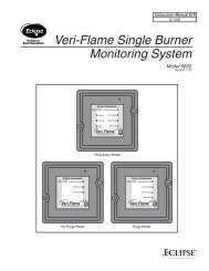
FLAME ROD<br />
FLAME GROUND<br />
IGNITION ELECTRODE<br />
(C7005B ONLY)<br />
SPARK GAP<br />
1<br />
FLAME RETENTION NOZZLE<br />
1/2 X 6 INCH (152.4 mm)<br />
PIPE NIPPLE (1/2 -14 NPT<br />
EXTERNAL THREADS)<br />
RAJAH CONNECTORS<br />
1/2-14 NPT X 3/8-18 NPT<br />
ELBOW (NOT FURNISHED)<br />
3/8-18 NPT PIPE<br />
NIPPLE (NOT FURNISHED)<br />
MIXING TUBE<br />
(3/8-18 NPT X 1/4-18 NPT<br />
INTERNAL THREADS)<br />
PRIMARY AIR<br />
ADJUSTMENT<br />
1/4-18 NPT<br />
PIPE (NOT FURNISHED)<br />
4-9/16 (115)<br />
1-1/2<br />
(31)<br />
3/8-18 NPT<br />
1 SPARK GAP BETWEEN IGNITION ELECTRODE AND GROUND MUST BE<br />
1/8 TO 3/16 INCH (3.2 TO 4.8 mm).<br />
M3035B<br />
Fig. 1. C7005 gas pilot and flame rod<br />
assembly in in. (mm).<br />
Fig. 2. Improper position of flame rod<br />
assembly in in. (mm).<br />
1/2-14 NPT<br />
13-1/2<br />
(342)<br />
9-3/4<br />
(247)<br />
NOTE: THE FLAME ROD SHOULD BE LOCATED<br />
ON EITHER SIDE OR BELOW THE PILOT.<br />
WRONGM3038A<br />
3 60-2033—4
<strong>C7005A</strong>,B GAS PILOT AND FLAME ROD ASSEMBLIES<br />
M3036A<br />
M3037A<br />
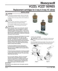
Fig. 4. Typical mounting of gas pilot and flame rod<br />
assembly on multiple head gas burner.<br />
Fig. 3. Typical mounting of gas pilot and flame rod<br />
assembly on radiant inshot type burner.<br />
On multiple head installations (Fig. 4), the pilot is usually<br />
centrally located. The pilot can usually be mounted vertically<br />
between burner heads with the pilot flame traveling upward<br />
across the junction of the gas stream from the burner heads. If<br />
the pilot is mounted horizontally on a level with the burner<br />
heads or the flat arch, the pilot flame should travel across the<br />
junction of the gas streams <strong>com</strong>ing from at least two heads.<br />
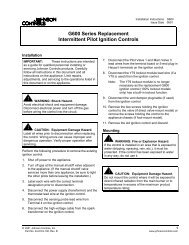
If a group of inspirating (Venturi type) burners are mounted<br />
within a burner box, sufficient spacing is usually available so<br />
the pilot can be mounted as illustrated in Fig. 5 to<br />
simultaneously light as many burners as possible. If available<br />
space does not allow central mounting within the burner box,<br />
see Fig. 3.<br />
MAIN BURNER<br />
C7005 GAS PILOT AND<br />
FLAME ROD ASSEMBLY<br />
PRIMARY<br />
IGNITION<br />
TRANSFORMER<br />
FURNACE<br />
M3039A<br />
Fig. 5. Typical mounting of gas pilot and flame rod<br />
assembly on inspirating (Venturi type) gas burner.<br />
60-2033—4 4
<strong>C7005A</strong>,B GAS PILOT AND FLAME ROD ASSEMBLIES<br />
WIRING<br />
CAUTION<br />
1. Turn off gas supply before starting installation.<br />
2. Disconnect power supply before beginning<br />
installation to prevent electrical shock and<br />
equipment damage. There may be more than one<br />
disconnect involved.<br />
All wiring must <strong>com</strong>ply with applicable electrical codes,<br />
ordinances, and regulations. Use NEC Class 1 (Line Voltage)<br />
wiring.<br />
For normal installations:<br />
• For the ignition electrode, use high tension wire<br />
electrically equivalent to type GTO-10, and rated for<br />
the temperature and humidity encountered in the<br />
application.<br />
• For the flame rod, use moisture-resistant no. 14<br />
AWG wire suitable for at least 167°F (75°C) if used<br />
with a flame safeguard primary control, or suitable<br />
for at least 194°F (90°C) if used with a flame<br />
safeguard programming control.<br />
For high temperature installations:<br />
• For the ignition electrode, use Honeywell<br />
specification no. R1061012 Ignition Cable or<br />
equivalent. (This wire is rated at 350°F [176°C] for<br />
continuous duty, and up to 500°F [260°C] for<br />
intermittent use. It has been breakdown tested to<br />
15,000 volts.)<br />
• For the flame rod, use Honeywell specification no.<br />
R1298020 or equivalent. This wire is rated up to<br />
400°F (204°C) for continuous duty. It is tested for<br />
operation up to 600 volts and breakdown up to 7500<br />
volts.<br />
For ignition installations in a contaminating environment, use<br />
Honeywell specification no. 32004766-003 High Tension<br />
Ignition Cable or equivalent. This wire is very resistant to<br />
severe conditions of oil, heat, and corona, and is tested to<br />
withstand high voltages up to 25,000 Vrms in a salt bath for<br />
one minute without breakdown. It is rated at 200°F (93°C) for<br />
continuous duty, and up to 350°F (176°C) for intermittent use.<br />
Make connections to the flame rod and ignition electrode<br />
(C7005B) using Rajah connectors. See Fig. 6 for typical field<br />
wiring connections.<br />
Connect the flame rod (see callout 1, Fig. 1) to the F terminal<br />
of the flame safeguard control. Keep this leadwire as short as<br />
possible; capacitance increases with leadwire length, reducing<br />
the flame signal strength. The ultimate limiting factor is the<br />
flame signal (see Table 1).<br />
For a C7005B:<br />
• Use a 6000 volt ignition transformer with the same<br />
electrical ratings as the power supply of the flame<br />
safeguard control.<br />
• Connect the primary leadwires of the ignition<br />
transformer between the ignition and the L2<br />
terminals of the flame safeguard control.<br />
• Connect the ignition electrode of the C7005B<br />
(callout 3, Fig. 1) to the secondary high tension<br />
terminal of the ignition transformer.<br />
PILOT<br />
HEAD<br />
FLAME<br />
ROD<br />
IGNITION<br />
ELECTRODE<br />
(C7005B ONLY)<br />
BURNER<br />
GROUND<br />
HIGH TENSION<br />
TERMINAL<br />
CASE<br />
GROUND<br />
SECONDARY<br />
6000 VOLT<br />
IGNITION<br />
TRANSFORMER<br />
Fig. 6. Typical field wiring diagram for C7005<br />
gas pilot and flame rod assembly.<br />
IMPORTANT<br />
Do not run high voltage ignition transformer wires in<br />
the same conduit with the flame rod wiring.<br />
No ground leadwires are required. The flame ground and flame<br />
retention nozzle (callouts 2 and 4, Fig. 1) act as the ground<br />
electrode for the flame rod and the ignition electrode. The case<br />
of the ignition transformer will act as the ground connection<br />
when it is securely fastened to the burner.<br />
ADJUSTMENTS AND CHECKOUT<br />
Adjust the Air-<strong>Gas</strong> Mixture<br />
PRIMARY<br />
IMPORTANT<br />
For initial burner lightoff, consult the burner manufacturer’s<br />
instructions or the instructions for the flame<br />
safeguard control.<br />
With the gas pilot installed and the pilot burner running, adjust<br />
the primary air adjustment (callout 10, Fig. 1) for an air-gas<br />
mixture that provides the type of flame required for the particular<br />
installation. Be sure you have the proper mixing tube for the type<br />
of gas (natural or LP) being used. A medium-hard flame<br />
generates the greatest response from the flame detector circuit.<br />
If air movement conditions are severe or change with<br />
modulation, it may be desirable to operate the premixed pilot<br />
on moderate to high gas pressure (normally not more than one<br />
psi). This is particularly true when the main burner fires with<br />
high pressure gas. Increasing the pilot pressure tends to<br />
harden and lengthen the pilot flame, increasing its stability<br />
under adverse draft conditions.<br />
Adjust <strong>Flame</strong> <strong>Rod</strong> Position<br />
The pilot flame must make good contact with the flame rod and<br />
furnish reliable ignition for the main burner. Check to be sure<br />
that the flame rod is located at the junction of the main burner<br />
flame and the pilot flame. Ensure that the main valve opens or<br />
unlocks only when the pilot flame is strong enough to ignite the<br />
main burner.<br />
Secondary air velocity over the pilot nozzle must not cause<br />
unstable flame contact with the flame rod, because this<br />
produces chattering of the flame detector relay.<br />
F<br />
L2<br />
FLAME<br />
SAFEGUARD<br />
CONTROL<br />
M3034A<br />
5 60-2033—4
<strong>C7005A</strong>,B GAS PILOT AND FLAME ROD ASSEMBLIES<br />
Measure the <strong>Flame</strong> Signal<br />
With the pilot and main burner(s) operating, adjust the position<br />
of the flame rod for optimum flame signal (current or voltage).<br />
Most existing Honeywell flame safeguard controls incorporate<br />
a flame signal jack located on the control amplifier or on the<br />
control itself. These controls require a Honeywell W136A Test<br />
Meter (see Fig. 7) or its equivalent for measuring the flame<br />
signal in microamperes. The flame signal (current) is<br />
measured by the following procedure:<br />
1. Use a Honeywell W136A Test Meter. (If a W136A is not<br />
available, a microammeter with a 0 to 25 microamp dc<br />
range can be used.)<br />
6. Read the average stable current. For an R7247B<br />
self-check rectification amplifier (AMPLI-CHECK), disregard<br />
the peaks due to self-checking operation. The red<br />
flame-indicating lamp on an R7247B should blink about<br />
2-1/2 to 4 times a second (from bright to dim). If the lamp<br />
is on or off continuously while reading the flame signal,<br />
replace the amplifier.<br />
NEGATIVE (-)<br />
METER LEAD<br />
POSITIVE (+)<br />
METER LEAD<br />
ONE MEGOHM/VOLT<br />
METER<br />
W136A VOLT-<br />
OHMMETER<br />
W136A SELECTOR<br />
SWITCH<br />
196146 METER<br />
CONNECTOR<br />
PLUG<br />
PLUG<br />
FLAME SIGNAL<br />
METER JACK<br />
M7382<br />
Fig. 8. Measuring flame signal voltage<br />
of 7800 SERIES control.<br />
RED (+)<br />
METER<br />
LEAD<br />
BLACK (-) METER LEAD<br />
RED CONNECTOR<br />
BLACK CONNECTOR<br />
PLUG-IN FLAME<br />
SIGNAL AMPLIFIER<br />
Fig. 7. Measuring microamp flame signal.<br />
M6532A<br />
2. Set the selector switch on the test meter to 25 uA for all<br />
standard amplifiers and flame safeguard controls, or to<br />
SPL for an R7247B AMPLI-CHECK self-check rectification<br />
amplifier. (If the test meter is not a W136A, shunt<br />
the 0 to 25 microamp dc range with a 50 microfarad<br />
capacitor.)<br />
3. Use a 196146 Meter Connector Plug (ordered separately).<br />
Connect the red spade tip to the red (+) meter<br />
lead and the black spade tip to the black (–) meter lead.<br />
4. Insert the plug into the flame signal meter jack and allow<br />
a few seconds for the meter reading to stabilize.<br />
5. When using a RA890H,J self-checking flame safeguard<br />
control, press the test button on the control to stabilize<br />
the current reading while making the measurement. The<br />
green flame indicating lamp should be on continuously<br />
while reading the flame signal.<br />
7. The meter reading must be as specified in Table 1 after<br />
all tests are <strong>com</strong>pleted and all adjustments are made.<br />
With the Honeywell 7800 Series controls, the flame signal is<br />
measured in Vdc. The voltage flame signal measurement<br />
requires a volt-ohmmeter with a minimum sensitivity of one<br />
megohm/volt and a 0 to 5 or10 Vdc scale. To make the flame<br />
signal measurement on 7800 SERIES controls, use the<br />
following procedure:<br />
1. Set the meter to the appropriate scale.<br />
2. Insert the positive (red) meter probe into the positive (+)<br />
jack of the 7800 SERIES control amplifier and the negative<br />
(black) probe into the negative (-Com) jack of the<br />
amplifier (see Fig. 8).<br />
3. Allow a few seconds for the meter reading to stabilize.<br />
4. When using an AMPLI-CHECK amplifier, read the<br />
average stable voltage and disregard the peaks due to<br />
the self-check operation.<br />
5. The flame signal voltage must be at least the minimum<br />
acceptable voltage as indicated in Table 1.<br />
6. If the 7800 SERIES control has the optional Keyboard<br />
Display Module, the flame signal will be displayed on the<br />
module.<br />
60-2033—4 6
<strong>C7005A</strong>,B GAS PILOT AND FLAME ROD ASSEMBLIES<br />
.<br />
Table 1. <strong>Flame</strong> Signal For <strong>C7005A</strong>,B.<br />
<strong>Flame</strong> Signal<br />
Amplifier<br />
R7247A<br />
R7247B a AMPLI-<br />
CHECK<br />
<strong>Flame</strong> Safeguard Control<br />
BC7000L; R4140G,L,M; R4138C,D;<br />
R4075C,D,E<br />
BC7000L; R4140G,L,M; R4138C,D;<br />
R4075C,D,E<br />
a Set W136A selector switch to SPL (damped) position to read current.<br />
b Press test button while reading current.<br />
Minimum<br />
Acceptable<br />
Steady Current<br />
(uA)<br />
2.0 5.0<br />
1.25 2.50<br />
R7257A R4150 2.0 5.0<br />
R7289A R4795 2.0 5.0<br />
R7847A<br />
RM7800E,G,L,M; RM7838A,B;<br />
RM7840E,G,L,M; RM7885A;<br />
RM7890A,B; RM7895A,B,C,D<br />
R7847B AMPLI-<br />
CHECK<br />
RM7800E,G,L,M; RM7838A,B;<br />
RM7840E,G,L,M; RM7885A;<br />
RM7890A,B; RM7895A,B,C,D<br />
None<br />
RA890F, R7795B,D,F,H; R7023B, 2.0 5.0<br />
R485<br />
None R4181 b 8.0 15.0<br />
Maximum<br />
Expected<br />
Current (uA)<br />
Minimum<br />
Acceptable<br />
Steady voltage<br />
(Vdc)<br />
1.25 5.0<br />
1.25 5.0<br />
Maximum<br />
Expected<br />
Steady voltage<br />
(Vdc)<br />
Measure the flame signal for the pilot alone, the main burner<br />
flame alone, and both together (unless monitoring only the pilot<br />
flame when using an intermittent pilot, or only the main burner<br />
flame when using direct spark ignition). Also measure the<br />
flame signal at high and low firing rates and while modulating<br />
in between (as applicable). With the detector in its final<br />
position, all required flame signals must be steady (or stable)<br />
and as specified in Table 1.<br />
If the signal is unstable or less than the minimum acceptable<br />
current, check the flame rod installation and circuitry:<br />
• Check the supply voltage at terminals L1-L2 on the wiring<br />
subbase or terminal strip for the flame safeguard control.<br />
• Check the wiring for defects including:<br />
— wrong type or size of wire.<br />
— deteriorated wire.<br />
— open circuits.<br />
— short circuits.<br />
— leakage paths caused by moisture, soot, or accumulated<br />
dirt.<br />
• Make sure:<br />
— there is enough ground area.<br />
— the flame rod is properly located in the flame.<br />
— temperature at the flame rod insulator is no greater<br />
than 500°F (260°C).<br />
— ignition interference is not present (see Ignition Interference<br />
Test below).<br />
• Make sure that the flame adjustment is not too lean.<br />
• If necessary, reposition the flame rod.<br />
If you cannot obtain proper operation, replace the plug-in<br />
amplifier if applicable. If you still cannot obtain proper<br />
operation, replace the flame rod.<br />
<strong>Pilot</strong> Turndown Test<br />
If the flame rod is used to prove a pilot flame before the main<br />
fuel valve can be opened, perform a <strong>Pilot</strong> Turndown Test.<br />
Follow the Instruction procedures for the appropriate flame<br />
safeguard control, and the burner manufacturer’s instructions.<br />
Ignition Interference Test<br />
C7005B<br />
Test to make certain that a false signal from the spark ignition<br />
system is not superimposed on the flame signal.<br />
Ignition interference can subtract from (decrease) or add to<br />
(increase) the flame signal. If it decreases the flame signal<br />
enough, it causes safety shutdown. (The flame relay will not<br />
pull in and the flame safeguard control will act as though the<br />
pilot or main burner, if using direct spark ignition, has not been<br />
ignited.) If it increases the flame signal, it could cause the<br />
flame relay to pull in when the true flame signal is below the<br />
minimum acceptable value.<br />
Test<br />
Start the burner and measure the flame signal with both ignition<br />
and pilot or main burner on, and then with only the pilot or<br />
main burner on. Any significant difference greater than 0.5<br />
microamp, or 0.25 Vdc with 7800 SERIES controls, indicates<br />
ignition interference.<br />
To Eliminate Ignition Interference<br />
1. Make sure there is enough ground area.<br />
2. Be sure the ignition electrode and the flame rod are on<br />
opposite sides of the ground area (Fig. 1).<br />
7 60-2033—4
<strong>C7005A</strong>,B GAS PILOT AND FLAME ROD ASSEMBLIES<br />
3. Check for correct spacing between the ignition electrode<br />
and ground for 6000 volt systems—1/8 to<br />
3/16 inch (3.2 to 4.8 mm).<br />
4. Make sure the leadwires from the flame rod and ignition<br />
electrode are not too close together.<br />
5. Replace any deteriorated leadwires.<br />
6. If the problem cannot be eliminated, consider changing<br />
to an ultraviolet flame detection system with a<br />
Q624A1014 solid-state spark generator.<br />
Final Checkout<br />
Before putting the burner into service, check out the<br />
installation by following the Checkout procedures in the<br />
Instructions for the appropriate flame safeguard control. After<br />
<strong>com</strong>pleting the checkout, run the burner through at least one<br />
<strong>com</strong>plete cycle to verify operation.<br />
OPERATION<br />
The C7005B <strong>Gas</strong> <strong>Pilot</strong> and <strong>Flame</strong> <strong>Rod</strong> Assembly includes an<br />
ignition electrode and a flame rod. The operation of these two<br />
electrodes in a simple electrically-operated, gas pilot<br />
installation is as follows.<br />
At the beginning of the starting cycle, a high voltage from the<br />
secondary winding of the ignition transformer is applied to the<br />
ignition electrode. A spark jumps across the outlet of the pilot<br />
burner. The pilot gas valve is either automatically or manually<br />
opened, and the spark ignites the gas.<br />
When the ignition transformer is energized, ac voltage is<br />
applied to the flame rod through a flame safeguard control.<br />
When the pilot flame appears, this ac voltage is changed to dc<br />
voltage through a rectifying action. This dc voltage then<br />
operates a relay, opening the valve to the main burner (or<br />
permitting it to be manually opened). In the event of flame<br />
failure, flame rectification stops, the gas valves are deenergized,<br />
the valves close, and the system shuts down.<br />
Automation and Control Solutions<br />
Honeywell International Inc. Honeywell Limited-Honeywell Limitée<br />
1985 Douglas Drive North 35 Dynamic Drive<br />
Golden Valley, MN 55422 Toronto, Ontario M1V 4Z9<br />
customer.honeywell.<strong>com</strong><br />
® U.S. Registered Trademark<br />
© 2006 Honeywell International Inc.<br />
60-2033—4 M.S. Rev. 08-06