41-553M.pdf - Pickering Interfaces
41-553M.pdf - Pickering Interfaces
41-553M.pdf - Pickering Interfaces
Create successful ePaper yourself
Turn your PDF publications into a flip-book with our unique Google optimized e-Paper software.
TABLE OF CONTENTS<br />
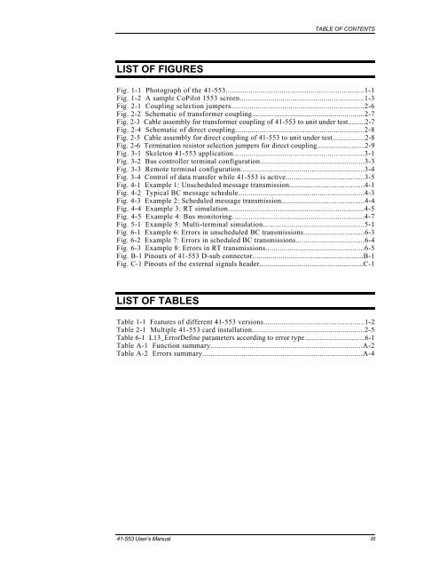
LIST OF FIGURES<br />
Fig. 1-1 Photograph of the <strong>41</strong>-553...................................................................1-1<br />
Fig. 1-2 A sample CoPilot 1553 screen.............................................................1-3<br />
Fig. 2-1 Coupling selection jumpers.................................................................2-6<br />
Fig. 2-2 Schematic of transformer coupling........................................................2-7<br />
Fig. 2-3 Cable assembly for transformer coupling of <strong>41</strong>-553 to unit under test.........2-7<br />
Fig. 2-4 Schematic of direct coupling...............................................................2-8<br />
Fig. 2-5 Cable assembly for direct coupling of <strong>41</strong>-553 to unit under test.................2-8<br />
Fig. 2-6 Termination resistor selection jumpers for direct coupling.........................2-9<br />
Fig. 3-1 Skeleton <strong>41</strong>-553 application................................................................3-1<br />
Fig. 3-2 Bus controller terminal configuration....................................................3-3<br />
Fig. 3-3 Remote terminal configuration.............................................................3-4<br />
Fig. 3-4 Control of data transfer while <strong>41</strong>-553 is active........................................3-5<br />
Fig. 4-1 Example 1: Unscheduled message transmission......................................4-1<br />
Fig. 4-2 Typical BC message schedule..............................................................4-3<br />
Fig. 4-3 Example 2: Scheduled message transmission..........................................4-4<br />
Fig. 4-4 Example 3: RT simulation..................................................................4-5<br />
Fig. 4-5 Example 4: Bus monitoring................................................................4-7<br />
Fig. 5-1 Example 5: Multi-terminal simulation..................................................5-1<br />
Fig. 6-1 Example 6: Errors in unscheduled BC transmissions...............................6-3<br />
Fig. 6-2 Example 7: Errors in scheduled BC transmissions...................................6-4<br />
Fig. 6-3 Example 8: Errors in RT transmissions.................................................6-5<br />
Fig. B-1 Pinouts of <strong>41</strong>-553 D-sub connector.......................................................B-1<br />
Fig. C-1 Pinouts of the external signals header....................................................C-1<br />
LIST OF TABLES<br />
Table 1-1 Features of different <strong>41</strong>-553 versions...................................................1-2<br />
Table 2-1 Multiple <strong>41</strong>-553 card installation........................................................2-5<br />
Table 6-1 L13_ErrorDefine parameters according to error type................................6-1<br />
Table A-1 Function summary..........................................................................A-2<br />
Table A-2 Errors summary..............................................................................A-4<br />
<strong>41</strong>-553 User’s Manual III


