Measuring an impedance by the oscilloscope. - dirac
Measuring an impedance by the oscilloscope. - dirac
Measuring an impedance by the oscilloscope. - dirac

You also want an ePaper? Increase the reach of your titles
YUMPU automatically turns print PDFs into web optimized ePapers that Google loves.
<strong>Measuring</strong> <strong>an</strong> imped<strong>an</strong>ce <strong>by</strong> <strong>the</strong><br />
<strong>oscilloscope</strong>.<br />
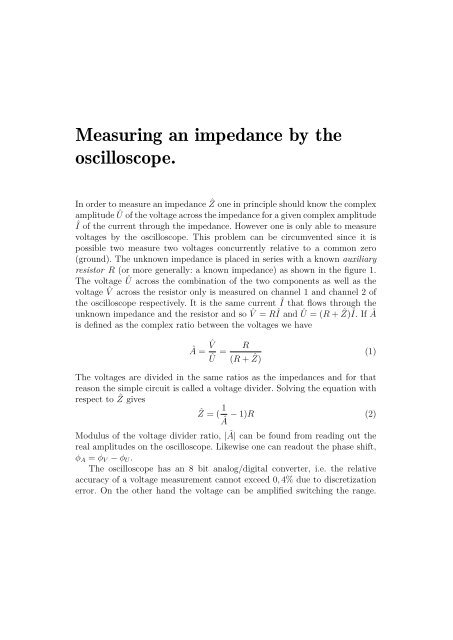
In order to measure <strong>an</strong> imped<strong>an</strong>ce Ẑ one in principle should know <strong>the</strong> complex<br />
amplitude Û of <strong>the</strong> voltage across <strong>the</strong> imped<strong>an</strong>ce for a given complex amplitude<br />
Î of <strong>the</strong> current through <strong>the</strong> imped<strong>an</strong>ce. However one is only able to measure<br />
voltages <strong>by</strong> <strong>the</strong> <strong>oscilloscope</strong>. This problem c<strong>an</strong> be circumvented since it is<br />
possible two measure two voltages concurrently relative to a common zero<br />
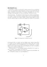
(ground). The unknown imped<strong>an</strong>ce is placed in series with a known auxiliary<br />
resistor R (or more generally: a known imped<strong>an</strong>ce) as shown in <strong>the</strong> figure 1.<br />
The voltage Û across <strong>the</strong> combination of <strong>the</strong> two components as well as <strong>the</strong><br />
voltage ˆV across <strong>the</strong> resistor only is measured on ch<strong>an</strong>nel 1 <strong>an</strong>d ch<strong>an</strong>nel 2 of<br />
<strong>the</strong> <strong>oscilloscope</strong> respectively. It is <strong>the</strong> same current Î that flows through <strong>the</strong><br />
unknown imped<strong>an</strong>ce <strong>an</strong>d <strong>the</strong> resistor <strong>an</strong>d so ˆV = RÎ <strong>an</strong>d Û = (R + Ẑ)Î. If Â<br />
is defined as <strong>the</strong> complex ratio between <strong>the</strong> voltages we have<br />
 = ˆV<br />
Û =<br />
R<br />
(R + Ẑ) (1)<br />
The voltages are divided in <strong>the</strong> same ratios as <strong>the</strong> imped<strong>an</strong>ces <strong>an</strong>d for that<br />
reason <strong>the</strong> simple circuit is called a voltage divider. Solving <strong>the</strong> equation with<br />
respect to Ẑ gives Ẑ = ( 1 − 1)R (2)<br />
Â<br />
Modulus of <strong>the</strong> voltage divider ratio, |Â| c<strong>an</strong> be found from reading out <strong>the</strong><br />
real amplitudes on <strong>the</strong> <strong>oscilloscope</strong>. Likewise one c<strong>an</strong> readout <strong>the</strong> phase shift,<br />
φ A = φ V − φ U .<br />
The <strong>oscilloscope</strong> has <strong>an</strong> 8 bit <strong>an</strong>alog/digital converter, i.e. <strong>the</strong> relative<br />
accuracy of a voltage measurement c<strong>an</strong>not exceed 0, 4% due to discretization<br />
error. On <strong>the</strong> o<strong>the</strong>r h<strong>an</strong>d <strong>the</strong> voltage c<strong>an</strong> be amplified switching <strong>the</strong> r<strong>an</strong>ge.
Figur 1 Voltage divider for imped<strong>an</strong>ce measurement.<br />
One should of course choose a r<strong>an</strong>ge for U(t) <strong>an</strong>d V (t) respectively in order<br />
<strong>the</strong> signals fill out <strong>the</strong> screen without being “cut”. It is not so import<strong>an</strong>t for<br />
high accuracy that ˆV becomes small. However it will give large errors if ˆV<br />
approaches Û since one c<strong>an</strong>’t amplify <strong>the</strong> difference between <strong>the</strong> those signals<br />
before <strong>the</strong> discretization. The method is thus going to be uncertain for |Z|
Figur 2 Alternative voltage divider for measuring <strong>an</strong> imped<strong>an</strong>ce.<br />
3