MACHINING OPERATIONS AND MACHINE TOOLS Drilling ...
MACHINING OPERATIONS AND MACHINE TOOLS Drilling ...
MACHINING OPERATIONS AND MACHINE TOOLS Drilling ...

Create successful ePaper yourself
Turn your PDF publications into a flip-book with our unique Google optimized e-Paper software.
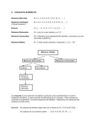
<strong>Drilling</strong><br />
<strong>MACHINING</strong> <strong>OPERATIONS</strong> <strong>AND</strong><br />
<strong>MACHINE</strong> <strong>TOOLS</strong><br />
MECN 4140 - Manufacturing Processes<br />
Inter American University of Puerto Rico<br />
Prof. Eduardo Cabrera Ruiz<br />
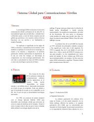
•Creates a round hole in<br />
a workpart<br />
•Compare to boring<br />
which can only enlarge<br />
an existing hole<br />
•Cutting tool called a drill<br />
or drill bit<br />
•Machine tool: drill press<br />
Figure 21.3 (b) drilling<br />
Based on ©2007 John Wiley & Sons, Inc. M P Groover, Fundamentals of Modern Manufacturing 3/e<br />
Page 2<br />
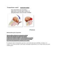
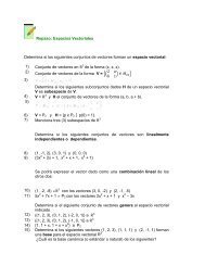
Through Holes vs. Blind Holes<br />
Through-holes - drill exits opposite side of work<br />
Blind-holes – does not exit work opposite side<br />
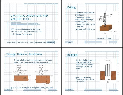
Reaming<br />
• Used to slightly enlarge a<br />
hole, provide better<br />
tolerance on diameter,<br />
and improve surface<br />
finish<br />
Figure 22.14 Machining<br />
operations related to drilling:<br />
(a) reaming<br />
Page 3<br />
Figure 22.13 Two hole types: (a) through-hole, and (b) blind hole.<br />
Page 4
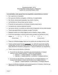
Tapping<br />
• Used to provide internal<br />
screw threads on an<br />
existing hole<br />
• Tool called a tap<br />
Counterboring<br />
• Provides a stepped hole,<br />
in which a larger diameter<br />
follows smaller diameter<br />
partially into the hole<br />
Figure 22.14 (c) counterboring<br />
Figure 22.14 (b) tapping<br />
Page 5<br />
Page 6<br />
Drill Press<br />
• Upright drill press stands on the<br />
floor<br />
• Bench drill similar but smaller and<br />
mounted on a table or bench<br />
Radial Drill<br />
Large drill press designed for<br />
large parts<br />
Figure 22.15 Upright drill press<br />
Figure 22.16 Radial drill press<br />
(photo courtesy of Willis<br />
Machinery and Tools).<br />
Page 7<br />
Page 8
Work Holding for Drill Presses<br />
• Workpart in drilling can be clamped in any of the following:<br />
– Vise - general purpose workholder with two jaws<br />
– Fixture - workholding device that is usually<br />
custom-designed for the particular workpart<br />
– Drill jig – similar to fixture but also provides a means<br />
of guiding the tool during drilling<br />
Milling<br />
Machining operation in which work is fed past a rotating tool<br />
with multiple cutting edges<br />
• Axis of tool rotation is perpendicular to feed<br />
• Creates a planar surface<br />
– Other geometries possible either by cutter path or<br />
shape<br />
• Other factors and terms:<br />
– Interrupted cutting operation<br />
– Cutting tool called a milling cutter, cutting edges called<br />
"teeth"<br />
– Machine tool called a milling machine<br />
Page 9<br />
Page 10<br />
Two Forms of Milling<br />
Peripheral Milling vs. Face Milling<br />
• Peripheral milling<br />
– Cutter axis parallel to surface being machined<br />
– Cutting edges on outside periphery of cutter<br />
• Face milling<br />
– Cutter axis perpendicular to surface being milled<br />
– Cutting edges on both the end and outside periphery of<br />
the cutter<br />
Figure 21.3 Two forms of milling: (a) peripheral milling, and<br />
(b) face milling.<br />
Page 12
Slab Milling<br />
•Basic form of peripheral milling in which the cutter width extends beyond<br />
the workpiece on both sides<br />
Slotting<br />
• Width of cutter is less than workpiece width,<br />
creating a slot in the work<br />
Figure 22.18 (a) slab<br />
milling<br />
Figure 22.18 (b) slotting<br />
Page 13<br />
Page 14<br />
Conventional Face Milling<br />
Cutter overhangs work on both<br />
sides<br />
Figure 22.20 (a) conventional face milling<br />
High speed face<br />
milling using indexable<br />
inserts (photo<br />
courtesy of<br />
Kennametal Inc.).<br />
Page 15<br />
Page 16
End Milling<br />
•Cutter diameter is less than work<br />
width, so a slot is cut into part<br />
Profile Milling<br />
Form of end milling in which the<br />
outside periphery of a flat part is<br />
cut<br />
Figure 22.20 (c) end milling<br />
Figure 22.20 (d) profile milling<br />
Page 17<br />
Page 18<br />
Pocket Milling<br />
•Another form of end milling used<br />
to mill shallow pockets into flat<br />
parts<br />
Surface Contouring<br />
•Ball-nose cutter fed back and forth<br />
across work along a curvilinear<br />
path at close intervals to create a<br />
three dimensional surface form<br />
Figure 22.20 (e) pocket<br />
milling<br />
Figure 22.20 (f) surface<br />
contouring<br />
Page 19<br />
Page 20
Equations<br />
Horizontal Milling Machine<br />
• Spindle rotation speed<br />
v<br />
N <br />
• Feed rate<br />
D<br />
f<br />
r<br />
Nn f<br />
t<br />
f r Feed rate mm/min (in/min)<br />
N = spindle speed rev/min<br />
n t = number of teeth on the cutter<br />
f = chip load in mm/tooth (in/tooth)<br />
Figure 22.23 (a) horizontal knee-and-column milling machine.<br />
Page 21<br />
Vertical Milling Machine<br />
Machining Centers<br />
Highly automated machine tool can perform multiple<br />
machining operations under CNC control in one setup with<br />
minimal human attention<br />
– Typical operations are milling and drilling<br />
– Three, four, or five axes<br />
• Other features:<br />
– Automatic tool-changing<br />
– Pallet shuttles<br />
– Automatic workpart positioning<br />
Figure 22.23 (b) vertical knee-and-column milling machine<br />
Page 24
Figure 22.26 Universal machining center; highly automated,<br />
capable of multiple machining operations under computer<br />
control in one setup with minimal human attention (photo<br />
courtesy of Cincinnati Milacron).<br />
Figure 22.27 CNC 4-axis turning center (photo courtesy of<br />
Cincinnati Milacron); capable of turning and related<br />
operations, contour turning, and automatic tool indexing, all<br />
under computer control.<br />
Mill-Turn Centers<br />
Highly automated machine tool that can perform turning,<br />
milling, and drilling operations<br />
• General configuration of a turning center<br />
• Can position a cylindrical workpart at a specified angle so a<br />
rotating cutting tool (e.g., milling cutter) can machine<br />
features into outside surface of part<br />
– Conventional turning center cannot stop workpart at a<br />
defined angular position and does not include rotating<br />
tool spindles<br />
Page 27<br />
Operation of Mill-Turn Center<br />
Figure 22.28 Operation of a mill-turn center: (a) example part with turned,<br />
milled, and drilled surfaces; and (b) sequence of operations on a mill-turn<br />
center: (1) turn second diameter, (2) mill flat with part in programmed<br />
angular position, (3) drill hole with part in same programmed position, and (4)<br />
cutoff.
Shaping and Planing<br />
•Similar operations<br />
•Both use a single point cutting tool moved linearly relative to<br />
the workpart<br />
Shaping and Planing<br />
• A straight, flat surface is created in both operations<br />
• Interrupted cutting<br />
– Subjects tool to impact loading when entering work<br />
• Low cutting speeds due to start-and-stop motion<br />
• Typical tooling: single point high speed steel tools<br />
Figure 22.29 (a) Shaping, and (b) planing.<br />
Page 29<br />
Page 30<br />
Shaper<br />
Planer<br />
Figure 22.30 Components of a shaper.<br />
Figure 22.31 Open side planer.
Broaching<br />
•Moves a multiple tooth cutting tool linearly relative to work in<br />
direction of tool axis<br />
Broaching<br />
Advantages:<br />
• Good surface finish<br />
• Close tolerances<br />
• Variety of work shapes possible<br />
Cutting tool called a broach<br />
• Owing to complicated and often custom-shaped geometry,<br />
tooling is expensive<br />
Figure 22.33 Broaching operation.<br />
Page 33<br />
Page 34<br />
Internal Broaching<br />
•Performed on internal surface of a hole<br />
•A starting hole must be present in the part to insert broach at beginning<br />
of stroke<br />
Sawing<br />
• Cuts narrow slit in work by a tool consisting of a series of<br />
narrowly spaced teeth<br />
• Tool called a saw blade<br />
• Typical functions:<br />
– Separate a workpart into two pieces<br />
Figure 22.34 Work shapes that can be cut by internal broaching;<br />
cross-hatching indicates the surfaces broached.<br />
– Cut off unwanted portions of part<br />
Page 35<br />
Page 36
Power Hacksaw<br />
Band Saw<br />
Figure 22.35 (b) bandsaw (vertical)<br />
– linear continuous motion of<br />
bandsaw blade, which is in the<br />
form of an endless flexible loop<br />
with teeth on one edge.<br />
Figure 22.35 (a) power hacksaw –linear reciprocating motion<br />
of hacksaw blade against work.<br />
Page 38<br />
Circular Saw<br />
High Speed Machining (HSM)<br />
Cutting at speeds significantly higher than those used in<br />
conventional machining operations<br />
• Persistent trend throughout history of machining is higher<br />
and higher cutting speeds<br />
• At present there is a renewed interest in HSM due to<br />
potential for faster production rates, shorter lead times,<br />
and reduced costs<br />
Figure 22.35 (c) circular saw – rotating saw blade provides<br />
continuous motion of tool past workpart.<br />
Page 40
High Speed Machining<br />
Page 41<br />
Conventional vs. high speed machining<br />
Indexable tools (face mills)<br />
Work material Conventional High speed<br />
speed<br />
m/min ft/min m/min ft/min<br />
Aluminum 600+ 2000+ 3600+ 12,000<br />
+<br />
Cast iron, soft 360 1200 1200 4000<br />
Cast iron, 250 800 900 3000<br />
ductile<br />
Steel, alloy 210 700 360 1200<br />
Source: Kennametal Inc.<br />
Other HSM Definitions – DN Ratio<br />
DN ratio = bearing bore diameter (mm) multiplied by<br />
maximum spindle speed (rev/min)<br />
• For high speed machining, typical DN ratio is between<br />
500,000 and 1,000,000<br />
• Allows larger diameter bearings to fall within HSM range,<br />
even though they operate at lower rotational speeds than<br />
smaller bearings<br />
Page 42<br />
Other HSM Definitions – HP/RPM Ratio<br />
hp/rpm ratio = ratio of horsepower to maximum spindle<br />
speed<br />
• Conventional machine tools usually have a higher hp/rpm<br />
ratio than those equipped for HSM<br />
• Dividing line between conventional machining and HSM is<br />
around 0.005 hp/rpm<br />
• Thus, HSM includes 15 hp spindles that can rotate at<br />
30,000 rpm (0.0005 hp/rpm)<br />
Other HSM Definitions<br />
• Emphasis on:<br />
– Higher production rates<br />
– Shorter lead times<br />
– Rather than functions of spindle speed<br />
• Important non-cutting factors:<br />
– Rapid traverse speeds<br />
– Automatic tool changes<br />
Page 43<br />
Page 44
Requirements for High Speed Machining<br />
• Special bearings designed for high rpm<br />
• High feed rate capability (e.g., 50 m/min)<br />
• CNC motion controls with “look-ahead” features to avoid<br />
“undershooting” or “overshooting” tool path<br />
• Balanced cutting tools, toolholders, and spindles to<br />
minimize vibration<br />
• Coolant delivery systems that provide higher pressures<br />
than conventional machining<br />
• Chip control and removal systems to cope with much larger<br />
metal removal rates<br />
High Speed Machining Applications<br />
• Aircraft industry, machining of large airframe components<br />
from large aluminum blocks<br />
– Much metal removal, mostly by milling<br />
• Multiple machining operations on aluminum to produce<br />
automotive, computer, and medical components<br />
– Quick tool changes and tool path control important<br />
• Die and mold industry<br />
– Fabricating complex geometries from hard materials<br />
Page 45<br />
Page 46<br />
End Lecture 6<br />
Lecture 7<br />
Page 47