the RydeFX Air 2.0 Service Manual - Hi-Performance Engineering
the RydeFX Air 2.0 Service Manual - Hi-Performance Engineering
the RydeFX Air 2.0 Service Manual - Hi-Performance Engineering

Create successful ePaper yourself
Turn your PDF publications into a flip-book with our unique Google optimized e-Paper software.
<strong>Service</strong>_Procedures
ArvinMeritor, Inc.<br />
2135 West Maple Road<br />
Troy, MI 48084 USA<br />
800-535-5560<br />
arvinmeritor.com<br />
Information contained in this publication was in effect at <strong>the</strong> time <strong>the</strong> publication was approved for<br />
printing and is subject to change without notice or liability. ArvinMeritor, Inc., reserves <strong>the</strong> right to<br />
revise <strong>the</strong> information presented or to discontinue <strong>the</strong> production of parts described at any time.<br />
ArvinMerotor, Inc. Copyright 2007 MM-0788<br />
All Rights Reserved Printed in USA April 15, 2007
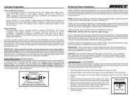
Hazard_Alert_Messages_<br />
Read and observe all Warning and Caution hazard alert messages in this publication.<br />
They provide information that can help prevent serious personal injury, damage to<br />
components, or both.<br />
How to Obtain Additional Maintenance and <strong>Service</strong> Information<br />
Call 1-800-901-7433 ext. 103 or email info@rydefx.com<br />
How to Obtain Special Tools and Supplies Specified in This Bulletin<br />
Call 1-800-901-7433 ext. 103 or email info@rydefx.com<br />
Required_Tools_<br />
• Interlocking Channel Pliers<br />
• 5/64” Allen Wrench<br />
• Slotted Head Screwdriver<br />
• Torque Wrench<br />
• 1/2” Wrench<br />
• Vernier Calliper or Micrometer<br />
• Pic Tool<br />
• Nitrogen Regulator<br />
• <strong>Air</strong> Compressor with blow gun attachment<br />
Specialty_Tools_<br />
• <strong>RydeFX</strong> Gas Charge Tool (Inflation Needle)<br />
ArvinMeritor P/n: 390300<br />
• <strong>RydeFX</strong> I.F.P Extraction / Locator Tool<br />
ArvinMeritor P/n: 390304<br />
• <strong>RydeFX</strong> <strong>Air</strong> Pump (Included)<br />
<strong>RydeFX</strong> <strong>Air</strong>_<strong>2.0</strong> 1 <strong>Service</strong> Procedures
Disassembly_<br />
n Warning_<br />
To prevent serious eye injury, always wear safe eye protection when<br />
you perform maintenance or service procedures.<br />
1. Wear safe eye protection.<br />
2. Remove <strong>the</strong> shock from <strong>the</strong> vehicle. Refer to your snowmobile owners<br />
manual for instructions on proper removal procedures.<br />
n Warning_<br />
Before using a solvent cleaner, you should be aware that it can be<br />
flammable, poisonous and cause burns. Some examples of solvent<br />
cleaners are carbon tetrachloride, and emulsion-type and petroleumbase<br />
cleaners. Carefully read and follow <strong>the</strong> manufacturer's instructions.<br />
Wear safe eye protection and clothing that protects your skin. Do not<br />
use gasoline, or solvents that contain gasoline. Gasoline can explode.<br />
Also take care that you correctly use hot solution tanks or alkaline<br />
solutions. Carefully read and follow <strong>the</strong> manufacturer's instructions.<br />
3. Wash <strong>the</strong> shock body parts in a solvent cleaner. Use compressed air<br />
to remove sand and dirt, and dry components.<br />
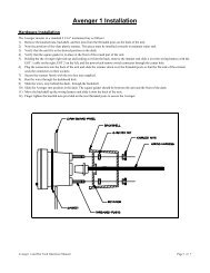
4. Remove bearing, sleeve and/or bushings<br />
from lower shock mount eyelet. Use a vise<br />
with soft-jaws to secure <strong>the</strong> lower mount<br />
of <strong>the</strong> shock absorber. If you secure <strong>the</strong><br />
shock absorber using any o<strong>the</strong>r method,<br />
you can damage or mark <strong>the</strong> shock<br />
absorber body cylinder. Figure <strong>2.0</strong><br />
Figure <strong>2.0</strong><br />
<strong>RydeFX</strong> <strong>Air</strong>_<strong>2.0</strong> 2 <strong>Service</strong> Procedures
5. Use Allen wrench to remove <strong>the</strong> small<br />
button head screws from <strong>the</strong> pressure<br />
valve assemblies at both ends of <strong>the</strong><br />
shock absorber. Figure 3.0<br />
Figure 3.0<br />
n Warning_<br />
The shock absorber contains nitrogen gas that is under extreme<br />
pressure. You must release all of <strong>the</strong> pressurized gas from <strong>the</strong> shock<br />
absorber before removing <strong>the</strong> pressure valve assembly. Use caution<br />
when releasing <strong>the</strong> gas and allow <strong>the</strong> pressure to discharge completely.<br />
Servicing a shock absorber that contains pressurized gas can cause<br />
<strong>the</strong> gas and shock absorber oil to eject <strong>the</strong> pressure valve assembly<br />
from <strong>the</strong> shock absorber body cylinder. Serious personal injury and<br />
damage to components can occur.<br />
6. Loosen <strong>the</strong> pressure valve assemblies on<br />
both ends of <strong>the</strong> shock absorber by using<br />
a slotted screwdriver to turn <strong>the</strong> pressure<br />
valve assembly screw counterclockwise two<br />
full rotations. Allow gas pressure to fully<br />
escape past each valve assembly O-ring.<br />
Gas chambers are depressurized when<br />
<strong>the</strong>re is no audible sound of escaping gas<br />
Figure 4.0<br />
Figure 4.0<br />
n Warning_<br />
Nitrogen gas is under extreme pressure. Use caution when releasing<br />
nitrogen gas from shock. Protective eyewear should be worn to avoid<br />
risk of injury.<br />
<strong>RydeFX</strong> <strong>Air</strong>_<strong>2.0</strong> 3 <strong>Service</strong> Procedures
7. Using a slotted screwdriver, remove <strong>the</strong> pressure valve assemblies from<br />
both ends of <strong>the</strong> shock absorber. Figure 5.0_5.1<br />
Figure 5.1<br />
Figure 5.0<br />
8. Use interlocking channel pliers to grip cylinder head and turn counter<br />
clockwise to loosen and remove cylinder head assembly. Figure 6.0_6.1<br />
Figure 6.1<br />
Figure 6.0<br />
9. Pour <strong>the</strong> shock oil out of <strong>the</strong> large diameter shock absorber cylinder.<br />
Discard <strong>the</strong> used oil into an approved storage container and dispose of<br />
it appropriately. Do not reuse <strong>the</strong> damper oil. Always use new oil for<br />
assembly procedures.<br />
<strong>RydeFX</strong> <strong>Air</strong>_<strong>2.0</strong> 4 <strong>Service</strong> Procedures
10.Using <strong>the</strong> compressed air blow gun, invert<br />
large diameter shock absorber cylinder on<br />
top of a folded shop rag. Hold <strong>the</strong> shock<br />
absorber firmly in place. Position <strong>the</strong> blow<br />
gun nipple into <strong>the</strong> cylinder pressure valve<br />
port. Charge <strong>the</strong> cylinder with 90 psi to<br />
remove <strong>the</strong> internal floating piston (I.F.P)<br />
from main working cylinder. Verify that <strong>the</strong><br />
wear band and O-ring are removed along<br />
with <strong>the</strong> internal floating piston (I.F.P). Figure 7.0<br />
Figure 7.0<br />
11.Clean <strong>the</strong> inside of <strong>the</strong> shock absorber body with a solvent cleaner. Use<br />
compressed air to dry <strong>the</strong> shock absorber.<br />
12.Place <strong>the</strong> 40mm piston rod upper mount<br />
into a bench vise. Remove <strong>the</strong> piston and<br />
valve. Arrange <strong>the</strong> parts in <strong>the</strong> order you<br />
disassembled <strong>the</strong>m. Figure 8.0<br />
Figure 8.0<br />
13.Inspect <strong>the</strong> following parts for wear and damage.<br />
Replace worn or damaged parts.<br />
a. 40mm Piston rod for straightness, nicks or burrs.<br />
b. Cylinder Head Assembly / DU Bearing – clean, inspect, or replace.<br />
c. Inside of shock body for scratches, burrs or excessive wear.<br />
d. Teflon piston and I.F.P wear band for cuts, chipped or nicked edges,<br />
or excessive wear.<br />
e. O-rings for nicks, cuts, or cracks.<br />
f. Valve discs for kinks or waves.<br />
g. Compression bumpers (ski shocks only) for chipping, cracking or<br />
being missing.<br />
<strong>RydeFX</strong> <strong>Air</strong>_<strong>2.0</strong> 5 <strong>Service</strong> Procedures
Assembly_<br />
1. Place <strong>the</strong> 40mm piston rod upper mount into <strong>the</strong> soft-jaw vise.<br />
Reassemble piston rod assembly in <strong>the</strong> order you disassembled it. Verify<br />
that <strong>the</strong> rebound and compression disc (shim) stacks are in <strong>the</strong> same<br />
order that <strong>the</strong>y were before disassembly.<br />
n Caution_<br />
Tighten <strong>the</strong> locking bolt to 28-32 ft-lb (39-44 Nm.). Do not overtighten<br />
<strong>the</strong> bolt. Damage to <strong>the</strong> piston and valves will occur.<br />
n Warning_<br />
Take care when you use LOCTITE® adhesive to avoid serious personal<br />
injury. Read <strong>the</strong> manufacturer's instructions before using this product.<br />
Follow <strong>the</strong> instructions carefully to prevent irritation to <strong>the</strong> eyes and<br />
skin. If LOCTITE ® adhesive material gets into your eyes, follow <strong>the</strong><br />
manufacturer's emergency procedures. Have your eyes checked by<br />
a physician as soon as possible.<br />
2. Apply LOCTITE® 290 threadlocking<br />
compound to <strong>the</strong> inside thread of <strong>the</strong> 40mm<br />
rod. Thread <strong>the</strong> piston assembly by hand.<br />
Use a torque wrench to tighten <strong>the</strong> locking<br />
bolt to 28-32 ft-lb (39-44 Nm.).<br />
Do not overtighten <strong>the</strong> locking bolt.<br />
Figure 10.0_10.1_10.2<br />
Figure 10.0<br />
Figure 10.2<br />
Figure 10.1<br />
<strong>RydeFX</strong> <strong>Air</strong>_<strong>2.0</strong> 6 <strong>Service</strong> Procedures
3. Apply of light film of white lithium grease to <strong>the</strong> counter bore of <strong>the</strong><br />
40mm piston rod pressure valve port.<br />
4. Use torque wrench to install <strong>the</strong> pressure<br />
assembly into <strong>the</strong> 40mm piston rod valve<br />
port and tighten to 100-110 in-lb (12-13 Nm.).<br />
Figure 11.0<br />
Figure 11.0<br />
NOTE: If you are using <strong>the</strong> <strong>RydeFX</strong> inflation tool to pressurize <strong>the</strong> piston<br />
rod assembly, refer to Procedures for Use of Replaceable Inflation Needle<br />
in <strong>the</strong> instruction manual included with <strong>the</strong> <strong>RydeFX</strong> tool case.<br />
5. Pressurize <strong>the</strong> 40mm piston rod assembly by adding nitrogen gas or<br />
compressed air through <strong>the</strong> pressure valve to <strong>the</strong> specified pressure<br />
(reference specification chart for correct gas pressure) The internal<br />
floating piston will be forced to <strong>the</strong> top of <strong>the</strong> cylinder beneath <strong>the</strong><br />
piston rod assembly. The 40mm piston rod assembly is now fully<br />
pressurized.Figure 1<strong>2.0</strong>_12.1<br />
Figure 12.1<br />
Figure 1<strong>2.0</strong><br />
Schrader valve adaptor may not be exactly as illustrated<br />
<strong>RydeFX</strong> <strong>Air</strong>_<strong>2.0</strong> 7 <strong>Service</strong> Procedures
6. Use a vise with soft-jaws to secure <strong>the</strong><br />
lower mount of <strong>the</strong> shock absorber. If you<br />
secure <strong>the</strong> shock absorber using any o<strong>the</strong>r<br />
method, you can damage or mark <strong>the</strong><br />
shock absorber body cylinder. Figure 13.0<br />
Figure 13.0<br />
NOTE: Depending on which shock absorber you are servicing, adjust <strong>the</strong><br />
I.F.P location tool to <strong>the</strong> specified depth.<br />
7. Thread <strong>the</strong> positioning head onto <strong>the</strong> I.F.P<br />
locator tool and adjust <strong>the</strong> top of <strong>the</strong> value<br />
indicator to <strong>the</strong> specified depth from <strong>the</strong> top<br />
of <strong>the</strong> 47mm cylinder (reference specification<br />
chart for correct depth measurement).<br />
Figure 14.0<br />
Figure 14.0<br />
8. Apply a thin film of shock oil onto <strong>the</strong><br />
floating wear band and O-ring. Install <strong>the</strong><br />
floating piston into <strong>the</strong> top of <strong>the</strong> shock<br />
absorber body. Position <strong>the</strong> piston<br />
approximately 1.0” (25mm) in depth.<br />
Figure 15.0<br />
Figure 15.0<br />
<strong>RydeFX</strong> <strong>Air</strong>_<strong>2.0</strong> 8 <strong>Service</strong> Procedures
9. Using <strong>the</strong> I.F.P Locator tool as a handle,<br />
push <strong>the</strong> floating piston down into <strong>the</strong><br />
shock absorber, until <strong>the</strong> value indicator<br />
knob contacts <strong>the</strong> shock absorber body.<br />
Take care not to damage <strong>the</strong> I.F.P wear<br />
band and O-ring. The piston should now<br />
be positioned correctly. Figure 16.0<br />
Figure 16.0<br />
10.Apply of light film of white lithium grease to <strong>the</strong> counter bore of <strong>the</strong><br />
40mm piston rod pressure valve port.<br />
11.Use torque wrench to install <strong>the</strong> pressure<br />
assembly into <strong>the</strong> 47 cylinder valve port<br />
and tighten to 100-110 in-lb (12-13 Nm.).<br />
Figure 17.0<br />
Figure 17.0<br />
NOTE: During installation some shock absorber oil will overflow. Wrap a<br />
shop cloth around <strong>the</strong> shock absorber body to absorb any overflow.<br />
12.Fill <strong>the</strong> shock absorber body with new<br />
shock oil, preferably <strong>RydeFX</strong> SLIDE oil<br />
(reference specification chart for correct<br />
oil volume). Allow a couple of minutes for<br />
all <strong>the</strong> air bubbles to rise to <strong>the</strong> top to<br />
ensure no air is trapped. Trapped air can<br />
affect damper performance. Figure 18.0<br />
Figure 18.0<br />
<strong>RydeFX</strong> <strong>Air</strong>_<strong>2.0</strong> 9 <strong>Service</strong> Procedures
13.Inverted 40mm piston rod assembly.<br />
Pour a small amount of shock oil into<br />
<strong>the</strong> center of <strong>the</strong> locking piston bolt, until<br />
oil purges from <strong>the</strong> bolt. Figure 19.0<br />
Figure 19.0<br />
14.With <strong>the</strong> cylinder head assembly pushed<br />
down against <strong>the</strong> piston, carefully insert<br />
<strong>the</strong> piston rod assembly into <strong>the</strong> cylinder.<br />
Slightly rotate <strong>the</strong> piston rod to allow piston<br />
to enter shock body bore. Figure 20.0<br />
Figure 20.0<br />
NOTE: Slowly push <strong>the</strong> piston rod and assembly into shock body. If you<br />
push it too quickly, you will displace <strong>the</strong> internal floating piston (I.F.P) from<br />
its original position, which can affect damper performance.<br />
15.Slowly push <strong>the</strong> piston rod and assembly into <strong>the</strong> shock absorber body,<br />
until <strong>the</strong> cylinder head assembly bottoms on <strong>the</strong> cylinder counter bore.<br />
Use a slight up-and-down movement, if necessary, to allow all air to<br />
pass through <strong>the</strong> piston assembly.<br />
16.Use interlocking channel pliers to grip <strong>the</strong><br />
cylinder head. Turn <strong>the</strong> head clockwise to<br />
tighten it securely onto <strong>the</strong> shock absorber<br />
cylinder. Figure 21.0<br />
Figure 21.0<br />
<strong>RydeFX</strong> <strong>Air</strong>_<strong>2.0</strong> 10 <strong>Service</strong> Procedures
NOTE: If you are using <strong>the</strong> <strong>RydeFX</strong> inflation tool to pressurize <strong>the</strong> 47mm<br />
shock absorber cylinder, refer to Procedures for Use of Replaceable<br />
Inflation Needle in <strong>the</strong> instruction manual included in <strong>the</strong> <strong>RydeFX</strong> tool case.<br />
17.Pressurize <strong>the</strong> shock absorber 47mm main working cylinder by adding<br />
nitrogen gas or compressed air through <strong>the</strong> pressure valve to <strong>the</strong><br />
specified pressure (reference specification chart for correct gas pressure).<br />
Once <strong>the</strong> shock absorber is pressurized, <strong>the</strong> piston rod should fully<br />
extend from <strong>the</strong> shock absorber body. Figure 2<strong>2.0</strong>_22.1<br />
Figure 22.1<br />
Figure 2<strong>2.0</strong><br />
Schrader valve adaptor may not be exactly as illustrated<br />
18.Install <strong>the</strong> small button head screw into <strong>the</strong> pressure valve assembly<br />
and tighten securely.<br />
19.Reinstall sleeve and bushings in lower shock absorber mount.<br />
<strong>RydeFX</strong> <strong>Air</strong>_<strong>2.0</strong> 11 <strong>Service</strong> Procedures
1<br />
3<br />
4<br />
2<br />
5<br />
6<br />
7<br />
8<br />
9<br />
10<br />
11<br />
12<br />
14<br />
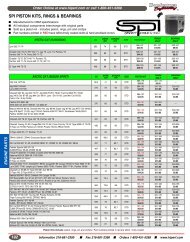
ITEM COMPONENT<br />
1 END CAP<br />
2 COMPRESSION BUMPER<br />
3 BUSHING<br />
4 SLEEVE<br />
5 CYLINDER HEAD ASSEMBLY<br />
6 INTERNAL FLOATING PISTON (IFP)<br />
7 IFP O-RING<br />
13<br />
ITEM COMPONENT<br />
8 ROD HEAD ASSEMBLY + SPRING<br />
9 PISTON<br />
10 TOP OUT WASHER<br />
11 PISTON BUSHING<br />
12 IFP O-RING WEAR BAND<br />
13 VALVE SCREW<br />
14 PRESSURE VALUE<br />
<strong>RydeFX</strong> <strong>Air</strong>_<strong>2.0</strong> 12 <strong>Service</strong> Procedures
<strong>Air</strong>_Pump_and<br />
Schrader_Valve_Kit_<br />
All aftermarket <strong>RydeFX</strong> AIR <strong>2.0</strong> shock absorbers come with an optional air<br />
pump and Schrader valve kit which can be used as an alternative method<br />
to adjusting <strong>the</strong> pressure of <strong>the</strong> shock absorber air spring. Installing <strong>the</strong><br />
Schrader valve kit, along with use of <strong>the</strong> air pump, accommodates <strong>the</strong> ease<br />
of adjustment to <strong>the</strong> 47mm cylinder spring pressure while on <strong>the</strong> trail or as a<br />
substitute to using nitrogen gas with <strong>the</strong> <strong>RydeFX</strong> Gas Fill Tool (P/n: 390300).<br />
n Warning_<br />
To prevent undesirable changes in dampening performance, it is<br />
recommended that you follow <strong>the</strong> manufacturer guidelines when<br />
making air pressure and IFP (Internal Floating Piston) adjustments<br />
to your AIR <strong>2.0</strong> shock absorbers with <strong>the</strong> Schrader valve kit.<br />
GAS PRESSURE ADJUSTMENTS TO SPRING PRE-LOAD<br />
47mm Aluminum Cylinder Gas Chamber Adjustments<br />
It is recommended that adjustments are only made to <strong>the</strong> gas chamber in<br />
<strong>the</strong> 47mm aluminum cylinder as this modifies <strong>the</strong> initial air spring pressure<br />
(preload) of <strong>the</strong> shock stroke and should be a sufficient adjustment for <strong>the</strong><br />
majority of riders. Use only <strong>Air</strong> or Nitrogen gas when making adjustments<br />
to air spring pressure.<br />
It is recommended that you do not increase <strong>the</strong> pressure in <strong>the</strong> 47mm<br />
aluminum cylinder gas chamber by more than 20-40 PSI at a time or<br />
beyond a maximum pressure of 100 PSI.<br />
n Caution_<br />
A change of 5 PSI in ei<strong>the</strong>r direction can have a significant impact on<br />
ride quality. Adjustments to air pressure should be made in small<br />
increments to avoid harsh handling.<br />
<strong>RydeFX</strong> <strong>Air</strong>_<strong>2.0</strong> 13 <strong>Service</strong> Procedures
40mm Piston Rod Gas Chamber Adjustments<br />
It is recommended that you do not adjust <strong>the</strong> pressure in <strong>the</strong> 40mm<br />
chrome cylinder. It has been set-up from <strong>the</strong> factory to ensure <strong>the</strong>re is<br />
sufficient stroke while preventing <strong>the</strong> shock from bottoming out. The gas<br />
chamber in <strong>the</strong> 40mm chrome cylinder is charged to 160 PSI from <strong>the</strong><br />
factory and adjusts <strong>the</strong> final portion of <strong>the</strong> shock stroke.<br />
PROCEDURES FOR INSTALLING SCHRADER VALVE KIT<br />
n Warning_<br />
To prevent serious eye injury, always wear safe eye protection<br />
when you perform maintenance or service procedures.<br />
1. Wear safe eye protection<br />
2. Use Allen wrench to remove <strong>the</strong> small button head screw from<br />
pressure valve assembly from <strong>the</strong> 47mm cylinder end.<br />
n Warning_<br />
The shock absorber contains nitrogen gas that is under extreme<br />
pressure. You must release all of <strong>the</strong> pressurized gas from <strong>the</strong> shock<br />
absorber before removing <strong>the</strong> pressure valve assembly. Use caution<br />
when releasing <strong>the</strong> gas and allow <strong>the</strong> pressure to discharge<br />
completely. Servicing a shock absorber that contains pressurized<br />
gas can cause <strong>the</strong> gas and shock absorber oil to eject <strong>the</strong> pressure<br />
valve assembly from <strong>the</strong> shock absorber body cylinder. Serious<br />
personal injury and damage to components can occur.<br />
3. Loosen pressure value assembly by using a slotted screwdriver to turn<br />
<strong>the</strong> pressure valve assembly screw counter clockwise two full rotations.<br />
Allow gas pressure to fully escape past <strong>the</strong> valve assembly O-ring. The<br />
gas chamber is depressurized when <strong>the</strong>re is no audible sound of<br />
escaping gas.<br />
4. Remove <strong>the</strong> pressure valve assembly from <strong>the</strong> 47mm cylinder end.<br />
5. Thread <strong>the</strong> Schrader valve assembly in clockwise and hand tighten<br />
using a 1/2” wrench.<br />
<strong>RydeFX</strong> <strong>Air</strong>_<strong>2.0</strong> 14 <strong>Service</strong> Procedures
Pump_Instructions_<br />
To Use:<br />
1. Thread silver pump head onto shock absorber valve<br />
2. Inflate shock absorber to desired pressure<br />
3. Adjust pressure by pressing bleed valve to release <strong>2.0</strong>-3.0 psi at a time<br />
4. Unthread pump head from <strong>the</strong> shock absorber valve<br />
NOTE: You may hear a release of air when you detach <strong>the</strong> pump from <strong>the</strong><br />
shock absorber valve. This air is being released from <strong>the</strong> pump hose, not<br />
from <strong>the</strong> shock absorber.<br />
MM-0788<br />
Issued April 15, 2007<br />
Page 7 Copyright ArvinMeritor Inc. 2007<br />
<strong>RydeFX</strong> <strong>Air</strong>_<strong>2.0</strong> 15 <strong>Service</strong> Procedures