Beam Forming Algorithm Implementation using FPGA - IRD India
Beam Forming Algorithm Implementation using FPGA - IRD India
Beam Forming Algorithm Implementation using FPGA - IRD India

You also want an ePaper? Increase the reach of your titles
YUMPU automatically turns print PDFs into web optimized ePapers that Google loves.
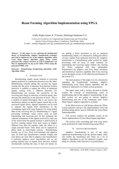
<strong>Beam</strong> <strong>Forming</strong> <strong>Algorithm</strong> <strong>Implementation</strong> <strong>using</strong> <strong>FPGA</strong><br />
Arathy Reghu kumar, K. P Soman, Shanmuga Sundaram G.A<br />
Centre for Excellence in Computational Engineering and Networking<br />
Amrita VishwaVidyapeetham, Coimbatore,TamilNadu, <strong>India</strong><br />
E-mail : rarathy18@gmail.com, kp_soman@amrita.edu, ga_ssundaram@cb.amrita.edu<br />
Abstract – In this paper we are exploring the fundamental<br />
theory of beamforming, adaptive beamforming technique<br />
and tried to implement one of the adaptive algorithm called<br />
Least Mean Square algorithm <strong>using</strong> Xilinx system<br />
generator.The compact structure of <strong>FPGA</strong> beamformer can<br />
thus be implemented on any of the Xilinx <strong>FPGA</strong> <strong>using</strong> the<br />
generated VHDL code.<br />
Keywords – <strong>Beam</strong>forming, beamforming algorithms, LMS<br />
<strong>Algorithm</strong>, Xilinx.<br />
I. INTRODUCTION<br />
<strong>Beam</strong>forming simply means transmit or receiving<br />
signals preferred in a particular direction over the other.<br />
<strong>Beam</strong>forming actually taking into account the signal<br />
coming into the array of antennas from desired location<br />
moreover it nullifies or reduce the effect of undesired<br />
signals coming from a different direction [1].<br />
<strong>Beam</strong>forming can increase the sensitivity of the<br />
receiving part along its direction of desired signal, also<br />
decrease the sensitivity in the direction of noise. This is<br />
a method of spatial filtering[2], that it can remove the<br />
interference pattern on desired signal caused due to the<br />
unwanted signal effects. Spatial separation can be used<br />
to separate the signals from interference by the<br />
overlapping signal with same frequency by <strong>using</strong> spatial<br />
filter at the receiving end [3]. <strong>Beam</strong>forming is a signal<br />
processing technique <strong>using</strong> sensor array at both<br />
transmitting and receiving part. In this technique the<br />
coherent summation of the signals received by each one<br />
of the sensor from the spatial location is achieved [4]. It<br />
involves sending signals from each sensor at slightly<br />
different time thus all together make the effect of a<br />
single powerful beam. Time delay can be replaced by<br />
phase shifts in narrowband systems. <strong>Beam</strong>forming<br />
broadly are of two, fixed (conventional) and adaptive<br />
type. In fixed type beamformers constant weights and<br />
time delays are used. But in adaptive type beamformers<br />
it performs adaptive noise cancellation and we are<br />
getting optimal type of signals from direction without<br />
mechanically steering the array. It does not means we<br />
are getting a beam maximum to get an optimum<br />
beamforming output, it is obtained by nulling the effects<br />
of noisy signals from undesired direction [5]. Adaptive<br />
beamformer is a beamforming radar system for signal<br />
processing with an array of radar antennas for<br />
transmitting and receiving signal without any steering<br />
[6]. When compared with data independent<br />
beamformers the adaptive ones have better resolution<br />
and interference rejection capability. But if any steering<br />
vector mismatch occurs it will affect the performance of<br />
the system [7].<br />
The main purpose of this paper is to do a discussion<br />
regarding the beamforming technique, adaptive<br />
beamforming Least Mean Square algorithm and the<br />
method to implement it in Xilinx system generator.<br />
The paper starts with a section devoted to briefly<br />
explain the concept of beamforming, types of<br />
beamforming and in that adaptive beamforming. In the<br />
IInd section we are going to discuss adaptive<br />
beamforming and one of the commonly used „Least<br />
Mean Square‟ adaptive algorithm is in detail.<br />
In the IIIrd section we will discuss about the Xilinx<br />
system generator and give the implementation tools and<br />
problem defing blocks used in Xilinxfor the Least Mean<br />
Squarealgorithm.<br />
IVth section explains the probable results of the<br />
Xilinx implemention of Least Mean Square algorithm<br />
Vth section is the concluding part with some future<br />
work mentioned for radar beamforming <strong>using</strong> <strong>FPGA</strong>.<br />
II. ADAPTIVE BEAMFORMING<br />
Adaptive beamforming is one of the most<br />
significant beamforming to get the desired output, while<br />
also nullify the interference [8]. There are a lot of<br />
adaptive algorithms to get the optimum weights, only<br />
thing we consider while selection is its performance.<br />
53<br />
ISSN (Print) : 2278-8948, Volume-2, Issue-3, 2013
International Journal of Advanced Electrical and Electronics Engineering, (IJAEEE)<br />
Commonly used adaptive algorithms are Least<br />
Mean Square, Sample Matrix Inverse and Recursive<br />
least square [9].<br />
LEAST MEAN SQUARE ALGORITHM<br />
Widrow proposed the least mean squares (LMS).<br />
The LMS algorithm is based on the minimum mean<br />
squares error [9]. It can be used for the purpose of<br />
adaptive interference canceling, adaptive beamforming,<br />
and adaptive control. LMS algorithm is a less<br />
randomness adaptive algorithm and can be used for<br />
nonstationary signal processing. The performances of<br />
the LMS algorithm have been extensively studied. If<br />
interference only exists in the output of the analyzed<br />
system, the LMS algorithm can only obtain the optimal<br />
solutions of signal processing problems [11].<br />
Least mean square algorithm is used to improve the<br />
output by updating the weights of the system and thus<br />
converge at the optimum weights.<br />
Fig 1 depicts the simple LMS beamforming<br />
network. LMS is <strong>using</strong> the method of steepest descent.<br />
Successive correction of the weight vector in the<br />
negative direction of the gradient term. For making use<br />
of gradient of mean square error function it does not<br />
even need squaring averaging or differentiation [12].<br />
The present weight vector is termed as w(n) and the<br />
successive weight is represented as w(n+1).<br />
Gradient vector in above weight update equation is<br />
Unlike in steepest descent method LMS uses<br />
instantaneous values of r and R instead of its actual<br />
values<br />
The updated weight can be written as<br />
The algorithm starts with initial weight as zero, with<br />
successive updation of weights the mean squared error<br />
get minimized. Thus the working of the system can be<br />
summarized as:<br />
Output is:<br />
2<br />
( E { e ( n )}) 2 r 2 Rw ( n ) (4)<br />
w<br />
R ( n) x( n) x ( n) (5)<br />
*<br />
h<br />
r ( n) d ( n) x( n) (6)<br />
w( n 1) w( n) x( n) e * ( n) (7)<br />
w( n 1) w( n) x( n)[ d * ( n) x ( n) w( n)]<br />
h<br />
Error is<br />
Tap weight is<br />
If the scalar constant φ is chosen to be small then<br />
algorithm converges slowly, large value for φ offers<br />
faster convergence [13, 14, 15].<br />
Fig. 1: adaptive beamforming network [13]<br />
By <strong>using</strong> the steepest descent method<br />
Where φ is the scalar constant for convergence control.<br />
e 2 (n)is the mean square error between d(n) and y(n)<br />
y(n) = w h x(n) (2)<br />
e 2 (n)= [d(n) − w h x(n)] 2 (3)<br />
1<br />
2<br />
w( n 1) w( n) [ ( E e ( n) )] (1)<br />
2<br />
III. XILINX SYSTEM GENERATOR FOR DSP<br />
<strong>FPGA</strong>s are now more admired than other<br />
frameworks like DSPs because of its reconfigurable<br />
nature.[16] But problem comes if the user does not have<br />
a previous knowledge about HDL coding. As the study<br />
of VHDL coding is a tedious task for a beginner, Xilinx<br />
system generator is a perfect platform. Previous<br />
experience on <strong>FPGA</strong> and coding is not needed in Xilinx,<br />
users can design blocks according to their problem<br />
defined <strong>using</strong> Xilinx blockset. It is able to generate the<br />
HDL code and it can then be processed on any Xilinx<br />
<strong>FPGA</strong>.[16,18,19]<br />
54<br />
ISSN (Print) : 2278-8948, Volume-2, Issue-3, 2013
International Journal of Advanced Electrical and Electronics Engineering, (IJAEEE)<br />
IMPLEMENTATION OF THE LMS ALGORITHM USING<br />
XILINX SYSTEM GENERATOR<br />
The system design diagram includes system<br />
generator block. A signal generator is used to give the<br />
input signal [16]. State control is given to enable or reset<br />
pins. Addressable shift register is there to for input and<br />
for updated weight vector. Multiply and accumulate is<br />
needed for multiplying the input with weights and<br />
accumulating. Error checking block needed to find error<br />
value between d(n) and y(n), also multiply it with the<br />
scalar constant φ. Weight update for finding out the<br />
successive weights.[15,16,18]<br />
The implementation part of the LMS design is<br />
done <strong>using</strong> the MATLAB 2011 and the Xilinx ISE 13.1<br />
version. The block mentioned below is created <strong>using</strong><br />
the specific blockset in system generator. The clock rate<br />
for <strong>FPGA</strong> is set as 1 MHZ.<br />
Delays are provided in state control. It can be set<br />
by setting the latency value. We can made necessary<br />
changes for each block by clicking and opening the<br />
blocks, then do the editing. The content of addressable<br />
registercan be read <strong>using</strong> the counters provided.<br />
Number of coefficients in the weight vector decides the<br />
counter depth. The input here is a sine wave.<br />
.<br />
Fig. 2: Block diagram of the LMS adaptive algorithm implemented <strong>using</strong> Xilinx blockset [16]<br />
Fig 3: Represents the input signal x(n), and the desired signal response from an unknown system d(n), Out response by multiplying<br />
and accumulating y(n) and finally the error e(n). [16]<br />
55<br />
ISSN (Print) : 2278-8948, Volume-2, Issue-3, 2013
International Journal of Advanced Electrical and Electronics Engineering, (IJAEEE)<br />
Fig. 4: Represents the top level RTL view of LM<br />
Fig. 5: Internal structure of LMS in RTL view<br />
.<br />
IV. CONCLUSION AND FUTURE WORK<br />
In this paper we have explored the theory behind<br />
the beamforming. LMS algorithm working for adaptive<br />
beamformers. Steps to implement this LMS algorithm<br />
on a Xilinx platform. Xilinx system generator is very<br />
helpful in designing real time implementations like the<br />
beamforming concept used RADAR technology.<br />
Xilinx will automatically generate a VHDL code<br />
for the corresponding block set which we have designed<br />
in thesystem generator. This generated code can be<br />
further used to do the hardware implementation part of<br />
<strong>FPGA</strong> beamformer on any Xilinx <strong>FPGA</strong>.<br />
Here we have discussed onlya single algorithm, but<br />
we can extend this work by creating blocksets for other<br />
recent adaptive algorithms and thus implementation on<br />
Xilinx <strong>FPGA</strong> <strong>using</strong> the generated VHDL code. Thus it<br />
will be worth while if we can do the <strong>FPGA</strong><br />
beamforming for the RADAR technology.<br />
56<br />
ISSN (Print) : 2278-8948, Volume-2, Issue-3, 2013
International Journal of Advanced Electrical and Electronics Engineering, (IJAEEE)<br />
V. REFERENCE<br />
[1] A Compact <strong>FPGA</strong> <strong>Beam</strong>former Architecture,Ioan Lie,<br />
MihailEugenTanase,2005 WSEAS Int. Conf. on<br />
DYNAMICAL systems and control (pp463-<br />
466),Venice,Italy, November 2-4, 2005<br />
[2] Laboratory technique Spatial filtering<br />
http://cem01.ucsd.edu/~vitaliy/courses/ece182/18206fi<br />
les/SpatialFiltering.pdf<br />
[3] <strong>Beam</strong>forming a versatile approach to spatial filtering,<br />
Barry D.VanVeen and Kevin M Buckley, IEEE ASSP<br />
MAGAZINE APRIL 1988<br />
[4] <strong>Beam</strong>forming for imaging a brief overview,<br />
JanEgilKirkebo,.<br />
[5] Antenna arrays and beamforming ch3.pdf<br />
http://scholar.lib.vt.edu/theses/available/etd-04262000-<br />
15330030/unrestricted/ch3.pdf<br />
[6] xhttp://en.wikipedia.org/wiki/Adaptive_beamformer<br />
[7] Kim.J.W and C K.UN An adaptive array robust to<br />
beam pointing errors, IEEE Trans Signal processing<br />
June 12, 2009<br />
[8] “A novel digital beamformer with low angle<br />
resolution for vehicle tracking radar,” Singh, A. K., P.<br />
Kumar, T. Chakravarty, G. Singh, andS. Bhooshan,<br />
Progress In Electromagnetics Research, PIER 66, 229–<br />
237, 2006<br />
[9] A simple adaptive beamforming algorithm with<br />
Interference suppression, K.Meena alias Jeyanthi1,<br />
Dr.A.P.Kabilan2 June 12, 2009<br />
[10] Total least mean squares algorithm Da-zheng feng,<br />
zheng bao, senior member, ieee, and li-cheng Jiao,<br />
senior member, IEEE transactions on signal<br />
processing, vol. 46, no. 8, august 1998<br />
[11] B widrow adaptive filters in aspects of networks and<br />
system theory,N de Claris and E kalman Eds. New<br />
York: Holt, Rinehart, and Winston, 1971<br />
[12] Interference-Normalized Least Mean Square <strong>Algorithm</strong><br />
Jean-Marc Valin, Member, IEEE, and Iain B.<br />
Collings, Senior Member, IEEE signal processing<br />
letters, vol. 14, no. 12, December 2007<br />
[13] Least Mean Square algorithm Ch_6lms.pdf<br />
K.K.Shetty,2004<br />
[14] <strong>FPGA</strong> implementation of Adaptive LMS filter S.S<br />
Godbole1, P.M Paldoskar2, VP Route3, proceeding of<br />
SPIT-IEEE colloquim and International conference<br />
Mumbai, <strong>India</strong> Vol. 2,2 26<br />
[15] Adaptive filters, Bernard Widrow. adaptive filters.pdf<br />
1971<br />
[16] <strong>Implementation</strong> of System Identification with<br />
Pipelined LMS Adaptive <strong>Algorithm</strong> <strong>using</strong> Xilinx<br />
System Generator for DSP Muhammad Sulman and<br />
Syed AmjadHussain Shah,2010<br />
[17] <strong>FPGA</strong> <strong>Implementation</strong> of NLMS <strong>Algorithm</strong> for<br />
Receiver in wireless communication system, IJCSNS<br />
International Journal of Computer Science and<br />
Network Security, VOL.10 No.12, December 2010<br />
[18] A pipelined LMS adaptive FIR filter architecture<br />
without adaptation delay, Douglas, ScottCSignal<br />
Processing, IEEE Transactions Mar1998.<br />
[19] Virtex <strong>FPGA</strong> implementation of a pipelined adaptive<br />
LMS predictor for electronic support measures<br />
receivers Ting, Lok-Kee K. Jan. 2005<br />
<br />
57<br />
ISSN (Print) : 2278-8948, Volume-2, Issue-3, 2013