SubDrive Duplex Alternator - Franklin Electric
SubDrive Duplex Alternator - Franklin Electric
SubDrive Duplex Alternator - Franklin Electric

You also want an ePaper? Increase the reach of your titles
YUMPU automatically turns print PDFs into web optimized ePapers that Google loves.
<strong>SubDrive</strong> <strong>Duplex</strong><br />
<strong>Alternator</strong><br />
Installation Manual
<strong>SubDrive</strong> <strong>Duplex</strong> <strong>Alternator</strong><br />
Contents<br />
Descriptions and Features. ..................................... 3<br />
Included Items ............................................... 4<br />
How It Works. ...............................................5-6<br />
Before Getting Started ......................................... 6<br />
Controller Location Selection ................................... 7<br />
<strong>SubDrive</strong> <strong>Duplex</strong> <strong>Alternator</strong> Quick Reference Guide ................ 8<br />
Installation Procedure ......................................... 9<br />
Wiring Connections ........................................10-13<br />
Start-Up and Operation .....................................13-14<br />
Mounting Dimensions ........................................ 15<br />
Accessories. ................................................ 15<br />
Diagnostic Fault Codes ....................................... 16<br />
Specifications ............................................... 17<br />
Appendix<br />
1. <strong>Duplex</strong> Inline Constant Pressure Quick Reference Guide ......... 18<br />
Tables<br />
1. <strong>SubDrive</strong>, MonoDrive, and Inline Models ........................ 3<br />
Figures<br />
1. Mounting Screws ........................................... 9<br />
2. Drive Sensor Cable Connections ............................. 10<br />
3. Pressure Sensor Connections. ............................... 11<br />
4. Alarm Connections. ........................................ 13
<strong>SubDrive</strong> <strong>Duplex</strong> <strong>Alternator</strong><br />
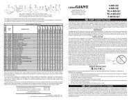
Table 1: <strong>SubDrive</strong> and MonoDrive Models<br />
Model Name<br />
<strong>SubDrive</strong> <strong>Duplex</strong><br />
<strong>Alternator</strong><br />
P a r t N u m b e r Use with <strong>SubDrive</strong> Series<br />
5850012000 5870203380 <strong>SubDrive</strong>75 NEMA 1<br />
5870203384 <strong>SubDrive</strong>75 NEMA 4<br />
5870204100 <strong>SubDrive</strong>100 NEMA 1<br />
5870204104 <strong>SubDrive</strong>100 NEMA 4<br />
5870204150 <strong>SubDrive</strong>150 NEMA 1<br />
5870204154 <strong>SubDrive</strong>150 NEMA 4<br />
5870206300 <strong>SubDrive</strong>300 NEMA 4<br />
5870203223 <strong>SubDrive</strong>2W<br />
5870203110 MonoDrive NEMA 1<br />
5870203114 MonoDrive NEMA 4<br />
5870204110 MonoDriveXT NEMA 1<br />
5870204114 MonoDriveXT NEMA 4<br />
90401101 Inline 1100<br />
90411101 Inline CP<br />
Note: <strong>SubDrive</strong> <strong>Duplex</strong> <strong>Alternator</strong> will work with any combination of the listed<br />
<strong>Franklin</strong> <strong>Electric</strong> <strong>SubDrive</strong>s/MonoDrives.<br />
Descriptions and Features<br />
The <strong>Franklin</strong> <strong>Electric</strong> <strong>SubDrive</strong> <strong>Duplex</strong> <strong>Alternator</strong> allows for two <strong>Franklin</strong> <strong>Electric</strong><br />
<strong>SubDrive</strong> units to operate on the same water system and share the work load<br />
equally. The <strong>Alternator</strong> will alternate between the two <strong>SubDrive</strong> units when the<br />
defined amount of run time has been reached. The <strong>Alternator</strong> is specifically<br />
designed for use with <strong>Franklin</strong> <strong>Electric</strong> <strong>SubDrive</strong> products (see Table 1 above).<br />
Key features of the <strong>Alternator</strong> include the following:<br />
3<br />
• Works with entire <strong>SubDrive</strong><br />
product family<br />
• Selectable alternate timing<br />
• Pump status indicator lights<br />
• Fault detection<br />
• Fail safe operation<br />
• Manual override push-button<br />
• Alarm circuit contacts<br />
• NEMA 4 enclosure<br />
• Low voltage wiring connections
<strong>SubDrive</strong> <strong>Duplex</strong> <strong>Alternator</strong><br />
Included Items<br />
A<br />
B<br />
F<br />
C<br />
G<br />
<strong>SubDrive</strong> <strong>Duplex</strong><br />
<strong>Alternator</strong><br />
Installation Manual<br />
D<br />
E<br />
H<br />
A. Controller Unit<br />
B. Sensor Cable (Pressure Sensors, 4-conductor)<br />
C. Sensor Cable (<strong>SubDrive</strong>s, 2-conductor) X2<br />
D. Mounting Brackets<br />
E. Outdoor Rated 120 VAC/12 VAC Transformer<br />
F. Transformer Output Cable<br />
G. Rubber Plug<br />
H. Installation Manual<br />
4
<strong>SubDrive</strong> <strong>Duplex</strong> <strong>Alternator</strong><br />
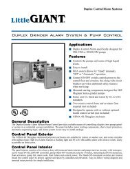
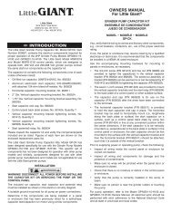
How It Works<br />
The <strong>Franklin</strong> <strong>Electric</strong> <strong>SubDrive</strong> <strong>Duplex</strong> <strong>Alternator</strong> is designed to be part of two<br />
independent <strong>SubDrive</strong> systems. Below is an example of a typical <strong>Alternator</strong><br />
System.<br />
<strong>Duplex</strong> <strong>Alternator</strong><br />
<strong>SubDrive</strong> 1 <strong>SubDrive</strong> 2<br />
Pressure Sensor<br />
Cables<br />
Pressure Tank<br />
To Power Supply<br />
To Power Supply<br />
Motor Cables<br />
Pressure Sensors<br />
<strong>SubDrive</strong> Pressure<br />
Sensor Connections<br />
(see Quick Reference Guide on<br />
pg. 8 for more detail on plumbing)<br />
Alternating <strong>SubDrive</strong> Systems<br />
The <strong>Alternator</strong> controls which drive is running the system by determining which<br />
pressure sensor each drive sees. The two pressure sensors in the system must<br />
have at least a 3 psi differential. The drive that uses the high set sensor will be in<br />
control of supplying water to the system. The other drive will be on the lower set<br />
sensor and will act as a backup. In the event that the primary drive cannot keep<br />
up with the water demand, the backup drive will automatically start and provide<br />
additional water. After the primary drive has reached its defined amount of run<br />
time, the <strong>Alternator</strong> will interchange the pressure sensors, thus causing the two<br />
drive units to switch roles.<br />
System Diagnostics<br />
In addition to alternating the two drive systems, the <strong>Alternator</strong> monitors the<br />
two systems to see if they are meeting the water demand as expected. If a<br />
system is not meeting the water demand as expected, the <strong>Alternator</strong> will lock<br />
the remaining system in as the primary system, declare a flash code indicating<br />
what kind of fault was found, close the alarm contacts, and not allow further<br />
alternation until the fault is cleared.<br />
5
<strong>SubDrive</strong> <strong>Duplex</strong> <strong>Alternator</strong><br />
Fail Safe Operation<br />
The <strong>Alternator</strong> is designed so that both <strong>SubDrive</strong> units are always linked to one<br />
pressure sensor or the other. If the <strong>Alternator</strong> should fail, the system will turn into<br />
a lead-lag system without the alternate function. Therefore, water will still<br />
be delivered even if the <strong>Alternator</strong> should fail.<br />
Additional Features<br />
The <strong>Alternator</strong> has a manual override button for selecting which <strong>SubDrive</strong> unit<br />
should be the primary system. The <strong>Alternator</strong> also has four different (push<br />
button) selectable timing modes ranging from 1 hour to 24 hours. These timing<br />
modes are based on the run time of the <strong>SubDrive</strong> unit. When a unit has run<br />
the selected amount of time, the <strong>Alternator</strong> automatically interchanges the<br />
primary and backup systems. In addition, the <strong>Alternator</strong> can be used with any<br />
combination of <strong>SubDrive</strong> products from <strong>Franklin</strong> <strong>Electric</strong>; one model fits all!<br />
Before Getting Started<br />
s ! WARNING<br />
For the indoor/outdoor transformer note the following:<br />
Risk of fire. If installation involves running wiring through a building<br />
structure, special wiring methods are needed. Consult a qualified electrician.<br />
Not for use with dimmers.<br />
s ! ATTENTION<br />
This equipment should be installed by technically qualified personnel.<br />
Installation must comply with <strong>Franklin</strong> <strong>Electric</strong>’s recommendations, national<br />
and local electrical codes. Failure to do so may result in electrical shock,<br />
fire hazard, unsatisfactory performance, or equipment failure. Installation<br />
information is available through pump manufacturers and distributors, or<br />
directly from <strong>Franklin</strong> <strong>Electric</strong> at our toll-free number 1-800-348-2420.<br />
s ! CAUTION<br />
Use the <strong>SubDrive</strong> <strong>Duplex</strong> <strong>Alternator</strong> only with <strong>Franklin</strong> <strong>Electric</strong> <strong>SubDrive</strong><br />
units as specified in this manual (see Table 1). Use of this unit with Variable<br />
Frequency Drives (VFDs) from other manufacturers may result in damage to<br />
both sets of electronics.<br />
6
<strong>SubDrive</strong> <strong>Duplex</strong> <strong>Alternator</strong><br />
Controller Location Selection<br />
The following recommendations will help in the selection of the proper location<br />
of the <strong>Alternator</strong> unit.<br />
1. A tee is recommended for mounting the two pressure sensors at<br />
one junction. If a tee is not used, the pressure sensors should<br />
be located within 6 feet (1.8 meters) of the pressure tank to<br />
minimize pressure fluctuations. The distance between the<br />
pressure sensors should be kept to a minimum. There should be<br />
no elbows between the tank and the pressure sensors.<br />
2. The unit should be mounted on a sturdy supporting structure<br />
such as a wall or supporting post.<br />
3. When installed properly, the <strong>Alternator</strong> enclosure is suitable for<br />
indoor or outdoor installations (see Installation Procedure section<br />
for details pg. 9).<br />
4. The <strong>Alternator</strong> should only be mounted with the wiring end<br />
oriented downward. The controller should not be placed in<br />
direct sunlight.<br />
5. The mounting location should have access to 115 VAC electrical<br />
supply. For outdoor installations the indoor/outdoor transformer<br />
must be connected to a GFCI outlet and follow all National,<br />
State, and Local electrical codes. Ensure that requirements of<br />
NEC 406.8 are met.<br />
6. To assure maximum weather protection, the unit must be<br />
mounted vertically with the cover snaps engaged.<br />
CORRECT<br />
INCORRECT<br />
Sensor Cables to Drives<br />
Power Supply<br />
from Transformer<br />
Sensor Cables from<br />
Pressure Sensors<br />
Sensor Cables from<br />
Pressure Sensors<br />
Sensor Cables to Drives<br />
Power Supply<br />
from Transformer<br />
7
<strong>SubDrive</strong> <strong>Duplex</strong> <strong>Alternator</strong><br />
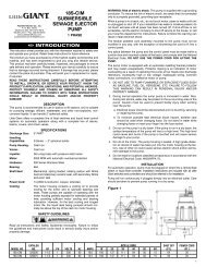
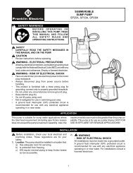
Quick Reference Guide <strong>SubDrive</strong> <strong>Duplex</strong> <strong>Alternator</strong><br />
Drive 1<br />
Drive 2<br />
Tank Pre-charge<br />
Inflation Valve<br />
Sensor Cable<br />
Supplied<br />
ALARM<br />
24VAC 1A MAX<br />
24 VDC 0.5A MAX<br />
1 2 1 2<br />
1 2 1 2<br />
PS-HI PS-LO PRESSURE 12 VAC<br />
SD1 SD2<br />
DRIVES<br />
SENSORS<br />
Drive Sensor<br />
Cables<br />
To<br />
Power<br />
Source<br />
To<br />
Power<br />
Source<br />
Pressure Gauge<br />
Motor Cable<br />
Pressure<br />
Sensor<br />
* Pressure<br />
Sensor<br />
*<br />
Motor Cable<br />
Pressure<br />
Relief Valve<br />
Drain Valve<br />
(To Residence)<br />
Discharge into<br />
drain rated for<br />
max pump output<br />
at relief pressure.<br />
Pump 1 Pump 2<br />
GFCI Outlet<br />
Motor 1<br />
Motor 2<br />
* When installing an <strong>Alternator</strong> with a<br />
<strong>SubDrive</strong> 300, do not hook up the pressure<br />
shut-off sensor to the <strong>Alternator</strong>. Only hook<br />
up the pressure sensors to the <strong>Alternator</strong>.<br />
Outdoor outlet cover<br />
for outdoor use<br />
8
<strong>SubDrive</strong> <strong>Duplex</strong> <strong>Alternator</strong><br />
Installation Procedure<br />
1. Disconnect electrical power at the main breaker.<br />
2. Drain the system (if applicable).<br />
3. Install the two <strong>SubDrive</strong> or Inline units per their installation instructions.<br />
4. Install the two pressure sensors on a tee downstream of the<br />
pressure tank (the pressure tank should be between the pressure<br />
sensors and the pump). The sensors have a ¼-18 National Pipe<br />
Thread (NPT) connection.<br />
5. Mount the <strong>Alternator</strong> unit in a suitable location using four<br />
mounting screws (not included) as shown in Figure 1 below.<br />
Figure 1: Mounting Screws<br />
Front View<br />
Mounting Screw Locations<br />
(User Supplied Quantity 4)<br />
Rear View<br />
Note: For installation procedures for the <strong>Duplex</strong> Inline Constant Pressure<br />
System refer to the <strong>Duplex</strong> Inline Constant Pressure System Quick Reference<br />
Guide (Appendix 1).<br />
9
1 2 1 2<br />
1 2 1 2<br />
PS-HI PS-LO SD1 SD2<br />
PRESSURE<br />
SENSOR<br />
SHUT-OFF<br />
INT<br />
FAN<br />
1 2 1 2<br />
1 2 1 2<br />
PS-HI PS-LO SD1 SD2<br />
O<br />
N<br />
ON<br />
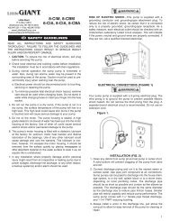
Wiring Connections<br />
<strong>SubDrive</strong> <strong>Duplex</strong> <strong>Alternator</strong><br />
1. Verify that the power has been shut off at the main breaker.<br />
2. Open the cover to the <strong>Alternator</strong>.<br />
3. Drive Connections<br />
Connect a two-conductor pressure sensor cable from Drive 1 to the<br />
<strong>Alternator</strong>’s terminal block labeled SD1 on the right side. The red and<br />
black wire connections are interchangeable. (See Figure 2 below).<br />
Whichever Drive unit is connected to the SD1 terminal will be the primary<br />
system first. The Drive unit connected to the SD2 terminal will be the<br />
backup system first.<br />
A. If connecting to a <strong>SubDrive</strong>300, use the supplied two-conductor<br />
pressure sensor cable. Cut the terminals off both ends of the red<br />
and black leads from the existing four-conductor cable. Leave<br />
only the Green and White leads linking the pressure shut-off<br />
switch to its connections on the <strong>SubDrive</strong>300.<br />
B. For all other <strong>SubDrive</strong>s, cut off the quick connect ends and strip<br />
the wire to make a two-conductor cable with stripped leads at<br />
both ends.<br />
4. Repeat step 3 for Drive 2, but connect Drive 2’s pressure sensor cable to<br />
the <strong>Alternator</strong>’s terminal block labeled SD2 on the right side.<br />
Figure 2: Drive Sensor Cable Connections<br />
(A)<br />
SW2 SW1<br />
<strong>Alternator</strong><br />
SW2 SW1<br />
(B)<br />
1 2<br />
SW1<br />
1 2 3 4<br />
PRESSURE<br />
SENSOR<br />
SHUT-OFF<br />
NO<br />
RELAY<br />
NO<br />
ALARM<br />
24V-1A<br />
PRESSURE<br />
SENSORS<br />
12 VAC<br />
DRIVES<br />
<strong>SubDrive</strong>300<br />
PFC<br />
FAN<br />
INV<br />
FAN<br />
COM<br />
<strong>SubDrive</strong><br />
<strong>Alternator</strong><br />
ALARM<br />
24V-1A<br />
PRESSURE<br />
SENSORS<br />
12 VAC<br />
DRIVES<br />
(Cut black and red wires; leave only<br />
the green and white connected to<br />
the pressure shut-off switch.)<br />
<strong>SubDrive</strong>300<br />
To Pressure Shut-off Switch<br />
Note: If using a NEMA 4 the quick connects or stripped leads may be used.<br />
10
<strong>SubDrive</strong> <strong>Duplex</strong> <strong>Alternator</strong><br />
5. Power Supply Connections.<br />
A. Run the output cable from the indoor/outdoor transformer into<br />
the <strong>Alternator</strong> through the center liquid tight strain relief (this is<br />
the strain relief with the largest diameter).<br />
B. Connect the output cable’s stripped leads to the terminal block<br />
labeled 12 VAC.<br />
C. Connect the other end of the output cable to the indoor/<br />
outdoor transformer’s secondary winding (the two<br />
prong connector).<br />
D. Either plug the transformer into a GFCI protected 115 VAC<br />
outlet or cut off the plug and strip the wires to connect the<br />
stripped leads to a 115 VAC power supply. If using a GFCI<br />
protected outlet follow the NEC 406.8 guidelines for protecting<br />
the outlet from the environment.<br />
Note: The transformer is rated for use indoor or outdoor so it can be mounted in<br />
any convenient location.<br />
6. Open Circuit Check. After completing steps 1-5 do the following:<br />
A. Apply power to the <strong>Alternator</strong> without applying power to<br />
the drives.<br />
B. The indicator lights should all be OFF except for the orange<br />
“1 hour” switching interval light. If the <strong>Alternator</strong>’s red light<br />
flashes, it means that there is an open circuit to one of the<br />
drives (see Diagnostic Fault Codes for specific flash code<br />
meaning pg. 16).<br />
C. Correct the open circuit; if one is found. The <strong>Alternator</strong> will<br />
stop flashing the red light when the open circuit is corrected.<br />
D. Disconnect power to the <strong>Alternator</strong> and continue to step 7.<br />
Figure 3: Pressure Sensor Connections<br />
1 2 1 2<br />
1 2 1 2<br />
PS-HI PS-LO<br />
PRESSURE 12 VAC<br />
SD1 SD2<br />
DRIVES<br />
SENSORS<br />
ALARM<br />
24V-1A<br />
1 2 1 2<br />
1 2 1 2<br />
PS-HI PS-LO<br />
PRESSURE 12 VAC<br />
ALARM SENSORS<br />
SD1 SD2<br />
DRIVES<br />
24VAC 1A MAX<br />
24 VDC 0.5A MAX<br />
Red<br />
Blue<br />
Green<br />
White<br />
Pressure Sensor High<br />
Pressure Sensor Low<br />
11
<strong>SubDrive</strong> <strong>Duplex</strong> <strong>Alternator</strong><br />
7. Pressure Sensor Connections.<br />
A. Connect the supplied four-conductor cable stripped leads to the<br />
<strong>Alternator</strong>’s terminal block labeled “Pressure Sensors”.<br />
B. Connect the Red and Black leads to the PS-HI part of the<br />
block. The Red and Black wire connections are<br />
interchangeable.<br />
C. Connect the White and Green leads to the PS-LO part of the<br />
block. The Green and White wire connections are<br />
interchangeable.<br />
D. Connect the other end of the four-conductor cable with the<br />
fork terminals to the two pressure sensors.<br />
E. Connect the Red and Black wires to the “high” set pressure<br />
sensor. Connect the stripped ends of the Red and Black wires<br />
to the <strong>Alternator</strong> (PS-HI). The Red and Black wire connections<br />
are interchangeable.<br />
F. Connect the Green and White wires to the “low” set pressure<br />
sensor. Connect the stripped ends of the Green and White wires to<br />
the <strong>Alternator</strong> (PS-LO). The Green and White wire connections<br />
are interchangeable. (See Figure 3 pg. 11).<br />
8. The two pressure sensors communicate the system pressure to the <strong>SubDrive</strong><br />
units. The <strong>Alternator</strong> requires that the pressure sensors have at least a 3 psi<br />
differential. The sensor connected to the <strong>Alternator</strong>’s PS-HI terminal must be the<br />
one set higher than the other sensor. The sensors are preset at the factory to 50<br />
psi, but must be adjusted by the installer using the following procedure:<br />
A. Remove the rubber end-cap (See Figure 3 pg. 11).<br />
B. Using a 7/32” Allen wrench, turn the adjusting screw clockwise<br />
to increase the pressure and counter-clockwise to decrease the<br />
pressure. The adjustment range is between 25 and 80 psi (1/4 turn =<br />
approximately 3 psi).<br />
C. Replace the rubber end cap.<br />
D. Cover the pressure sensor terminals with the rubber boot<br />
(See Figure 3 pg.11).<br />
Note: If the pressure sensors are not adjusted properly or connected to the<br />
wrong terminals on the <strong>Alternator</strong> the unit may not function properly. Make sure<br />
that the PS-HI terminal is connected to the pressure sensor that is set higher<br />
than the other pressure sensor.<br />
s ! CAUTION<br />
When increasing the pressure, do not exceed the mechanical stop on the<br />
pressure sensor or 80 psi. The pressure sensor may be damaged.<br />
12
<strong>SubDrive</strong> <strong>Duplex</strong> <strong>Alternator</strong><br />
9. The Alarm Contacts are an optional feature. The Alarm Contacts are a set<br />
of dry contacts that close when the <strong>Alternator</strong> declares a fault. These contacts<br />
are rated for a maximum of 24 VAC at 1A (amps) or 24 VDC at 0.5A (amps). Any<br />
type of external alarm indicating load may be attached to these dry contacts as<br />
long as the maximum voltage and current criteria is not exceeded. If the Alarm<br />
Contacts are not used; use the rubber pull-plug on the unused strain relief to<br />
seal the unit from the weather. (See Figure 4 below).<br />
Figure 4: Alarm Connections<br />
<strong>Alternator</strong><br />
(A)<br />
(B)<br />
1 2 1 2<br />
1 2 1 2<br />
PS-HI PS-LO<br />
PRESSURE 12 VAC<br />
SD1 SD2<br />
DRIVES<br />
ALARM SENSORS<br />
24VAC 1A MAX<br />
24 VDC 0.5A MAX<br />
1 2 1 2<br />
1 2 1 2<br />
PS-HI PS-LO<br />
PRESSURE 12 VAC<br />
SD1 SD2<br />
DRIVES<br />
ALARM SENSORS<br />
24VAC 1A MAX<br />
24 VDC 0.5A MAX<br />
Load<br />
(Use the rubber pull-plug on the<br />
unused strain relief to seal the<br />
unit from the weather).<br />
24 Volt AC or DC source (user supplied)<br />
24 VAC 1A Max<br />
24 VDC 0.5A Max<br />
10. When all the cables have been connected to the <strong>Alternator</strong>, tighten the 4<br />
smaller liquid-tight strain relieves around the cables to 25-30 in. lbs. and tighten<br />
the larger center strain relief to 55-60 in. lbs. to maximize the unit’s weather<br />
protection.<br />
Start-Up and Operation<br />
Apply power to the <strong>Alternator</strong> controller and the <strong>SubDrive</strong> units. Only the timing<br />
indicator light will be illuminated until the <strong>Alternator</strong> detects the presence of the<br />
<strong>SubDrive</strong> units. This will require letting the system come up to pressure. A steady<br />
green light indicates which pump system is the primary system and that it has no<br />
demand. A flashing green light indicates that a system has demand.<br />
13
Setting the Alternate Time<br />
<strong>SubDrive</strong> <strong>Duplex</strong> <strong>Alternator</strong><br />
The alternate time is set by pressing the button labeled “Change Interval”.<br />
One press will move the orange indicator light over one position; each position<br />
is labeled with a different alternate time. When the primary system has<br />
accumulated an amount of run time equal to the selected alternate time, the<br />
<strong>Alternator</strong> will switch the primary system to the backup system and the backup<br />
system to the primary system.<br />
Note: Changing the alternator time will NOT reset the cumulative clock.<br />
Fault Detection<br />
The <strong>Alternator</strong> continuously monitors the water system demand, checking to see<br />
if the water demand is being met as expected. If the water demand is not being<br />
met as expected, the <strong>Alternator</strong> will begin looking for possible problems with the<br />
system. While it’s looking, the <strong>Alternator</strong> will alternate the two drives back and<br />
forth a few times. After performing the check, the <strong>Alternator</strong> will either declare a<br />
fault or leave the system as it was if no problem was found.<br />
Manual Override/Clear Fault Button<br />
The manual override button allows the user to switch which <strong>SubDrive</strong> system<br />
is the primary system at any time. When the user presses the “Switch Pump or<br />
Clear Fault” button, the <strong>Alternator</strong> switches the primary system to the backup<br />
system and the backup system to the primary system. When this happens, the<br />
cumulative clock is RESET and begins counting again.<br />
The second function of this button is to clear a fault from the <strong>Alternator</strong>’s<br />
memory. If this button is held down for 5 seconds, the red Fault light will clear<br />
and the Alarm Relay will open.<br />
Note: If the <strong>Alternator</strong> loses power, it will not retain any faults found and will<br />
reset the cumulative clock. The <strong>Alternator</strong> will “relearn” a fault that was lost<br />
during loss of power.<br />
14
<strong>SubDrive</strong> <strong>Duplex</strong> <strong>Alternator</strong><br />
Mounting Dimensions<br />
5.80”<br />
7.35” 5.80”<br />
6.65”<br />
Accessories<br />
4.70” 3.60”<br />
<strong>Duplex</strong> to Pressure Sensor Cable Kit - 22 AWG 4-conductor pressure sensor<br />
cable:<br />
10 feet: 225597901<br />
100 feet: 225597902<br />
Drive to <strong>Duplex</strong> Cable Kit - 22 AWG 2-conductor pressure sensor cable:<br />
10 feet: 225597903<br />
100 feet: 225597904<br />
Indoor/Outdoor Transformer Kit<br />
225597905<br />
15
<strong>SubDrive</strong> <strong>Duplex</strong> <strong>Alternator</strong><br />
Diagnostic Fault Codes<br />
In the event that a problem occurs with one of the two Drive systems and the<br />
unit is unable to meet demand properly, the <strong>Alternator</strong>’s diagnostics will detect<br />
the problem and alert the user with a “Fault” light and close a set of dry contacts<br />
that can be connected to an external alarm. The red “Fault” light will flash a<br />
given number of times to indicate the nature of the fault. After a fault has been<br />
corrected, the <strong>Alternator</strong> can be reset by holding down the “Switch Pump or<br />
Clear Fault” button for 5 seconds or by removing power. The <strong>Alternator</strong> may also<br />
see that the system is functioning normal again and self clear the FAULT light<br />
and alarm. Fault codes and the recommended corrective action for each are<br />
listed in the chart.<br />
# of<br />
Flashes<br />
Fault Possible Cause Corrective Action<br />
1<br />
System 1 down<br />
or shorted low<br />
pressure sensor<br />
System 1 is not meeting<br />
demand properly or<br />
lower set pressure<br />
sensor is shorted<br />
Check Drive 1’s front panel for<br />
possible fault code and follow<br />
corrective actions for that fault code.<br />
Make sure that Drive 1 has a green<br />
light (i.e. it has power). If there is no<br />
fault code and a green light is present,<br />
check the lower set pressure sensor to<br />
see if its contacts are shorted together.<br />
2<br />
System 2 down<br />
or shorted low<br />
pressure sensor<br />
System 2 is not meeting<br />
demand properly or<br />
lower set pressure<br />
sensor is shorted<br />
Check Drive 2’s front panel for<br />
possible fault code and follow<br />
corrective actions for that fault code.<br />
Make sure that Drive 2 has a green<br />
light (i.e. it has power). If there is no<br />
fault code and a green light is present,<br />
check the lower set pressure sensor to<br />
see if its contacts are shorted together.<br />
3<br />
Open high<br />
pressure sensor<br />
Leads to higher set<br />
pressure sensor may be<br />
open or broken or the<br />
sensor itself may have<br />
failed to open<br />
Check the leads to the higher set<br />
pressure sensor. Check the sensor<br />
itself. Check the leads to <strong>Alternator</strong>’s<br />
terminal block.<br />
4<br />
Leads to Drive 1<br />
are open circuit<br />
Leads from Drive 1 to<br />
<strong>Alternator</strong> are damaged<br />
or not connected<br />
Check leads from Drive 1 to <strong>Alternator</strong>.<br />
Check connection at terminal block of<br />
Drive 1 and connection at <strong>Alternator</strong><br />
terminal block.<br />
5<br />
Leads to Drive 2<br />
are open circuit<br />
Leads from Drive 2 to<br />
<strong>Alternator</strong> are damaged<br />
or not connected<br />
Check leads from Drive 2 to <strong>Alternator</strong>.<br />
Check connection at terminal block of<br />
Drive 2 and connection at <strong>Alternator</strong><br />
terminal block.<br />
6<br />
Pressure<br />
sensors not<br />
set far<br />
enough apart<br />
Pressure sensor<br />
differential’s too close.<br />
Both Drives are trying to<br />
meet system demand at<br />
the same time<br />
Adjust pressure sensors so the PSI<br />
difference is great enough to get only<br />
one drive to run at a time; at least 3<br />
psi should be enough difference.<br />
16
<strong>SubDrive</strong> <strong>Duplex</strong> <strong>Alternator</strong><br />
Specifications<br />
Input from Power Source<br />
to Indoor/Outdoor<br />
Transformer<br />
Input to Controller Unit<br />
Pressure Setting (B)<br />
Voltage<br />
Frequency<br />
Voltage<br />
Frequency<br />
Power (A)<br />
Factory preset<br />
Adjustment range<br />
115 VAC<br />
60 Hz<br />
12 VAC<br />
60 Hz<br />
1.4 Watts<br />
50 psi<br />
25-80 psi<br />
NEMA 4 (indoor/outdoor) Model 5850012000<br />
Operating Conditions<br />
Controller Size<br />
(approximate)<br />
Temperature<br />
Relative humidity<br />
Outer dimensions<br />
Weight<br />
-13 to 125 ºF (-25 to 51 ºC)<br />
0-100%, non-condensing or<br />
condensing<br />
5.9” H x 5.9” W x 3.6” D<br />
1.3 lbs (0.59 kg)<br />
For Use With<br />
Note:<br />
<strong>Franklin</strong> <strong>Electric</strong> <strong>SubDrive</strong>s/<br />
MonoDrives<br />
(A) Power is on the secondary side of Transformer.<br />
(B) Pressure sensors must be set at least 3 psi apart.<br />
All models (see Table 1 pg. 3<br />
for details)<br />
17
<strong>SubDrive</strong> <strong>Duplex</strong> <strong>Alternator</strong><br />
Quick Reference Guide <strong>Duplex</strong> Inline – Typical Install Appendix 1<br />
Inline System<br />
Power<br />
4 Gallon<br />
Tank Minimum<br />
<strong>Duplex</strong><br />
<strong>Alternator</strong><br />
Pressure Gauge<br />
Water Supply<br />
Check<br />
Valve<br />
Pressure<br />
Relief<br />
Valve<br />
Ball Valve<br />
To Output Usage<br />
*Check Valve<br />
Optional Bypass ¹<br />
Ball Valve Manifold<br />
Check Manifold<br />
Flow<br />
Valve<br />
Check<br />
Valve<br />
Pressure Sensors ² & ³<br />
(Discharge into drain<br />
rated for max pump<br />
output at relief pressure)<br />
Ball Valve Check Valve<br />
*NOTICE: If system plumbing does not have a backflow prevention device a check valve is required on the incoming water supply line.<br />
NOTES:<br />
1. These optional components are shown in a typical installation diagram. They should be used at the installer's discretion as required for particular applications.<br />
2. If the optional high pressure shut-off kits (305707912) are being used on this duplex Inline Constant Pressure System, they should be installed as per the standard<br />
Inline Constant Pressure System Owner’s Manual, with one high pressure cut-off being wired directly to each Inline drive unit.<br />
3. 3 PSI differential required between these two sensors for proper operation of the system. Prior to wiring any components adjust the pressure setting in one of the sensors lower.<br />
Dimensions<br />
This is done by turning the hex pressure adjustment screw on the top of the switch by at least 1/4” turn counter clockwise (or 3 psi).<br />
18.84"<br />
[ 478.5 ]<br />
1.50"<br />
[ 38.1 ]<br />
3.45"<br />
10.43"<br />
[ 87.7]<br />
[ 265 ]<br />
1.25"<br />
NPT<br />
Inlet<br />
1.25"<br />
NPT<br />
Outlet<br />
Input<br />
Power<br />
5.72"<br />
[145.2]<br />
7.00"<br />
[177.8]<br />
8.00"<br />
[ 203.2]<br />
6.65"<br />
[ 168.9 ]<br />
2.92"<br />
[ 74.1]<br />
9.31"<br />
[ 236.4 ]<br />
17.32"<br />
[ 439.9 ]<br />
18
19<br />
Notes
TOLL-FREE HELP FROM A FRIEND<br />
<strong>Franklin</strong> <strong>Electric</strong><br />
Submersible Service Hotline<br />
800-348-2420<br />
400 East Spring Street, Bluffton, Indiana 46714<br />
Tel: 260.824.2900 Fax: 260.824.2909<br />
www.franklin-electric.com<br />
225589101<br />
225589101 REV 3<br />
M1557 06-11