T3 PRV Catalogue b&w.cdr - Atvus Industries
T3 PRV Catalogue b&w.cdr - Atvus Industries
T3 PRV Catalogue b&w.cdr - Atvus Industries

You also want an ePaper? Increase the reach of your titles
YUMPU automatically turns print PDFs into web optimized ePapers that Google loves.
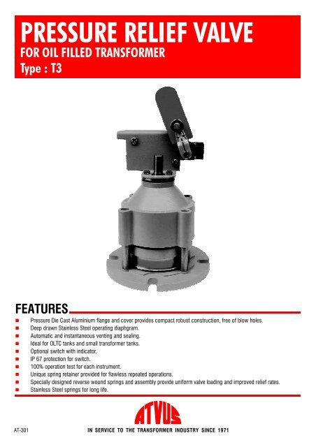
PRESSURE RELIEF VALVE<br />
FOR OIL FILLED TRANSFORMER<br />
Type :<strong>T3</strong><br />
FEATURES<br />
•<br />
•<br />
•<br />
•<br />
•<br />
•<br />
•<br />
•<br />
•<br />
•<br />
Pressure Die Cast Aluminium flange and cover provides compact robust construction, free of blow holes.<br />
Deep drawn Stainless Steel operating diaphgram.<br />
Automatic and instantaneous venting and sealing.<br />
Ideal for OLTC tanks and small transformer tanks.<br />
Optional switch with indicator.<br />
IP 67 protection for switch.<br />
100% operation test for each instrument.<br />
Unique spring retainer provided for flawless repeated operations.<br />
Specially designed reverse wound springs and assembly provide uniform valve loading and improved relief rates.<br />
Stainless Steel springs for long life.<br />
AT-301 IN SERVICE TO THE TRANSFORMER INDUSTRY SINCE 1971
9<br />
10<br />
6<br />
4<br />
8<br />
7<br />
5<br />
3<br />
1<br />
2<br />
CONSTRUCTION WORKING APPLICATION<br />
The Pressure Relief Valve<br />
consists of an integral flange (1)<br />
with gasket (2) for mounting on<br />
transformer tank. The Stainless<br />
Steel diaphragm (3) is spring (4)<br />
loaded and seals the 70 mm port<br />
against top and side gasket (5&6).<br />
The cover (7) retains and<br />
compresses the spring and is held<br />
in place by six screws (8). The<br />
spring retainer (9) prevents the<br />
dislocation of springs during<br />
repeatedoperations.<br />
The switch assembly (10) for<br />
alarm is optional and houses one<br />
NO and one NC contact (four<br />
terminals). It also has a visual<br />
indicator(11).<br />
When pressure in the tank<br />
rises above the safe limit, the<br />
operating disc moves slightly<br />
upwards from top gasket. This<br />
exposes the transformer pressure<br />
to agreater area corresponding to<br />
the diameter of side gasket,<br />
resulting in sudden increase of<br />
force.Thediskliftsinstantaneously<br />
and vents gases, vapour and liquid<br />
till the pressure falls to allowable<br />
values.<br />
These Pressure Relief Valves are<br />
recommended to be used on all<br />
sizes of OLTC and transformers<br />
ranging from 250 KVA to 5MVA.<br />
They are much more effective,<br />
durable, suitable for repeated<br />
operations than the conventionally<br />
usedexplosionvent.
MOUNTING<br />
The Pressure Relief Valve should be preferably<br />
mounted in the horizontal position, top side up. It may<br />
howeverbemountedonitsside,inverticalplane.<br />
DETAILS OF MOUNTING PAD<br />
4NOS. M10 TAPPED HOLE<br />
O<br />
ON 127P.C.D. AT90 APART<br />
INSTALLATION<br />
Clean surface of mounting pad on tank and place the<br />
flange with gasket. Use M12 x30 bolts with washers<br />
for tightening. Ensure that the gasket is placed in the<br />
grooveprovidedintheflange.<br />
TOP VIEW<br />
150<br />
68<br />
ALL DIMENSIONS ARE IN mm.<br />
Check the operation of switch by manually lifting the<br />
operating rod. After checking, the switch should be<br />
manually reset by placing the roller type knob back to<br />
itsoriginalposition.<br />
SECTIONALFRONTVIEW<br />
DETAILOFMOUNTINGPLATE<br />
(NOT SUPPLIED BYUS)<br />
HORIZONTAL &VERTICAL MOUNTING<br />
MAINTENANCE<br />
The Pressure Relief Valve has arugged construction<br />
and does not require any maintenance. The operating<br />
pressure is factory preset and cannot be changed at<br />
site. It is strongly recommended that the compression<br />
screws on the cover should never be removed without<br />
useofextremecaution.Theoperationofswitchmaybe<br />
periodicallytestedbymanually liftingtheoperatingrod<br />
and should be reset before putting the instrument in<br />
service.<br />
APPLICATION<br />
HORIZONTAL<br />
VERTICAL<br />
VALVE SPECIFICATIONS<br />
1. Liquid in tank : Transformer oil<br />
2<br />
2. Operating Pressure : 0.42 Kg/cm (6 PSI)<br />
2<br />
0.49 Kg/cm (7 PSI)<br />
2<br />
0.56 Kg/cm (8 PSI)<br />
2<br />
0.70 Kg/cm (10 PSI)<br />
3. Operating tolerance :<br />
2<br />
+ 0.07 Kg/cm (1.0 PSI)<br />
4. Operating time : Instantaneous<br />
O<br />
5. Operating temperature : 0to 100 C(of transformer oil)<br />
6. Portopening : 70 mm Dia<br />
7. Valve resetting : Automatic<br />
8. Switch : Limit Switch D.P.D.T.<br />
9. Switch resetting : Manual<br />
10. Environment : Indoor &Outdoor<br />
SWITCH SPECIFICATIONS<br />
1. Number of switch : 1Limit switch<br />
2. Operation : Automatic<br />
3. Contact rating : AC :240V 10 Amp<br />
DC :240V 0.4 Amp<br />
4. Number of contacts : 1NO +1NC<br />
2NO +2NC (optional)<br />
5. Weather protection : IP 67<br />
6. Cable entry : 3/4” Conduit
SWITCH OPERATION<br />
BEFORE VALVE OPERATION<br />
1 2 3<br />
4<br />
TERMINAL NOS.<br />
AFTER VALVE OPERATION<br />
HOLE FOR CABLE ENTRY<br />
(3/4" x16 TPI)<br />
LIMIT SWITCH<br />
1 2<br />
3 4<br />
WIRING DIAGRAM<br />
ALARM<br />
1<br />
2<br />
4NOS. LUGS<br />
12WIDE127 P.C.D.<br />
FOR MOUNTING<br />
SUPPLY<br />
ALARM<br />
3<br />
4<br />
150ø<br />
GASKET<br />
(SUPPLIED BY US)<br />
ALL DIMENSIONS ARE IN mm<br />
SUPPLY<br />
ToOrder,Or For Quotation, Specify :<br />
1. Model Number<br />
2. Operating Pressure<br />
-<strong>T3</strong> -With Switch (1 NO +1NC)<br />
-<strong>T3</strong>-2 -With Switch (2 NO +2NC)<br />
-<strong>T3</strong>W -Without Switch<br />
2<br />
a) 0.42 Kg/cm (6 PSI)<br />
2<br />
b) 0.49 Kg/cm (7 PSI)<br />
2<br />
c) 0.56 Kg/cm (8 PSI)<br />
2<br />
d) 0.70 Kg/cm (10 PSI)<br />
e) Other than above<br />
Due to our policy of continuous product improvement, dimensions and designs are subject to change.<br />
INDUSTRIES<br />
689, Block ‘O’, New Alipore, Kolkata -700 053, INDIA<br />
Phones: (91-33) 24001101, 24009885 Fax: (91-33) 24007443, 24007043 E-mail: atvus@dataone.in