Buchholz Relay Catalogue b&w.cdr - Atvus Industries
Buchholz Relay Catalogue b&w.cdr - Atvus Industries
Buchholz Relay Catalogue b&w.cdr - Atvus Industries

Create successful ePaper yourself
Turn your PDF publications into a flip-book with our unique Google optimized e-Paper software.
GENERALPower Transformers are consideredto be a highly reliable type ofequipment,yet,inorderto ensure thecontinuity of service that modernconditions demand, protectivedevices are required. The purpose ofsuch devices is to disconnect faultyapparatusbefore large-scale damageis caused by afault to the apparatusor to other connected apparatus.Such devices generally respond to achange in the current or pressurearising from the faults and are usedfor either signaling or tripping thecircuits.Protective devices in the ideal casemust be sensitive to all faults, simplein operation, robust for service andeconomically feasible. Consideringliquid immersed transformers, anear-ideal 'protective device' isavailable in the form of Gas and Oilrelay described here. The relayoperates on the well-known fact thatalmost everytype of electric fault in a'liquid immersed transformer' givesrisetogas.Thisgasiscollectedinthebody of the relay and is used in somewayorotherto causethealarmorthetrippingcircuittooperate.The principle of the Gas and Oil relaywas first successfully demonstratedand utilized by'<strong>Buchholz</strong>' manyyearsback. In a series of experimentscarried out extensively in Germany itwas proved that the <strong>Relay</strong> is capableof bringing to light incipient faultthereby preventing further spreadingofthefaultandextensivedamageandthus saving expensive and protractedrepairs.So successfulisthe principleof this <strong>Relay</strong> that despite thecontinued searchforbetterprotectivedevices in other electrical fields theGas-and-Oil<strong>Relay</strong>isstillonitsowninproviding protection against avarietyoffaults.WORKINGThe function of a double elementrelaywillbedescribedhere.During normal operation of atransformer the <strong>Buchholz</strong> relay iscompletely filled with oil. Buoyancyand the moment due tocounterweights keep the floats intheiroriginaltoppositions.In the event of some fault in theinterior of the transformer tank, gasbubbles are produced whichaccumulate in the <strong>Buchholz</strong> relay onthe way to the conservator. Inconsequence, the oil level in the relayenclosure drops which in turn lowerstheupperbucket.This causes the mercury switch tooperateanalarmsignal.The lower bucket doesnot change itsposition, because when the gasreaches the upper inside wall of thepipe it can escape into theconservator.Hence,minorfaultinthetransformer tank will not trigger thelower switching assembly and willnottripthetransformer.In case the liquid continues to dropdue to loss of oil, the lower bucketalso goes down.Inconsequence,thelower switching system operates ifthe level of oil goes below the bottomlevel of the pipe connected to therelay.Alternately in the event the liquid flowexceeds a specific value (which iscontinuouslyadjustable,bymeansofa flap) the lower bucket is forceddown, thus triggering the lowerswitchingsystemtooperate.As the liquid flow rate decreases, orthe level of the liquidrises,the bucketreturns to its original position. Thesingle element relay has only Tripelement and it responds to only oilsurges. The method of operation issimilar to that described for doubleelement relay. Single element relaysaresuitableforpotentialtransformersandonloadlapchangers.ThesingleelementoilSurgerelayhasbeen specifically designed for usewith on load tap change equipmentanditwillby-passnormalamountsofgas which are generated by tapchange operations and will onlyrespondtooilsurgesandlossofoil.APPLICATIONSDouble element relayscanbe used indetecting minor or major faults in atransformer. The alarm element willoperate, after aspecified volume ofgas has collected to give an alarmindication. Examples of incipientfaultsare(a) Broken-downcoreboltinsulation(b) Shortedlaminations(c) Badcontacts(d) OverheatingofpartofwindingsThealarmelementwillalsooperateinthe event of oil leakage, or if air getsintotheoilsystem.The trip element will be operated byan oil surge in the event of moreseriousfaultssuchas(a)(b)(c)(d)EarthfaultsWindingshortcircuitsPunctureofbushingsShortcircuitbetweenphasesThe trip element will also be operatedif a rapid loss of oil occurs. Singleelement relays can be used to detecteither incipient or major faults in oilfilled potential transformers,reactors, capacitors etc. A specialsingle element relay is available forthe protection of on load tap-changeequipment.
BASIC CHARACTERISTICSThe Gas and Oil <strong>Relay</strong> providesprotectionagainstanumberofinternalfaults and is also able to indicate inseveral cases the type of fault. This ispossible because the gas collected inrelay can, from its colour,odour andcomposition, indicate where the faultmay be and what its nature is. Byexamining the gases collected it ispossibletoinferthenatureoffault.Thus:(a) If the gas is colourless andodourless or with only a faintodour of oil, the gas is air trappedintheoilortheinsulation.(b) If the gas is Greyish white withsharp and penetrating odour andnon-inflammable it is due tooverheated or faulty insulation(fullerboardetc.)(c) IfthegasisYellowishincolourandinflammable it maybe due tosurface leakage on material likewood.(d) If the gas is dark Grey andinflammable it may be due to aflashoverinoilordueto excessiveoverheating of the oil caused by afaultinthewindingorthecore.On the operation of the alarm ifinvestigationof the collected gasdoesnot indicate a serious fault it ispossible to leave the transformer inservice till it is convenient to carry outa thorough inspection. Thisoccurrence is possible on a newlycommissioned transformer due to airtrapped in the oil or the insulation. Onrepeated and frequent alarm signalsthe transformer should be taken out ofserviceforthoroughcheckup.FUNCTIONAL TEST &ELECTRICAL CONNECTIONTesting the relay Function with theTest Key : Atest system is provided inthe <strong>Buchholz</strong> relay that allows thefunctional test of the upper and lowerswitchingsystem.Totesttherelayfunctionloosenthenutonthe Test Keyand rotate the keywitha screwdriver in the anticlockwisedirection till the SLOT on the Test Keypoints towards the T/L position. Boththe alarm (upper switching system)and Trip (lower switching system) willshowcontinuity.On bringing the SLOT on the Test Keyto S(service) position by rotating thekey clockwise the Alarm and Tripcircuits will not show continuity. Thecircuits will be actuated to 'ON'position only when there will afault inthetransformer.Repeat the functional test each time arelay is started or maintenancecompleted.Testing the relay function with theTest Pump : Screw the test pump tothetestcock.Openthetestcockandpumpairgentlyinto the <strong>Buchholz</strong> relay until the upperswitchingsystemoperates.For operating the lower switchingsystemairhastobepumpedsuddenlywith ajerk which will in turn operatethe lower switching system. The Tripelement may not operate with acyclepump.Electrical Connection : To allowinstallationofthe 'single wire' opentheterminal box cover comprising of thename plate and the instruction stickeron the backside. Then pass the wirethrough one of the three conduitscrewings into the terminal box. Theupper two studs are terminals for theAlarm switching circuit and aredenoted by A. Likewise the lower twostuds are terminals for the TripswitchingcircuitandaredenotedbyT.INSTALLATION&MAINTENANCEInstallation into pipeline : Forinstalling the relay into pipe-lineproceedsasfollows:• See that the <strong>Buchholz</strong> relay ispositioned with the arrow pointingtowards the conservator, theconnection box is the Y Plan(Vertical) and the Test Cock. (1.7)andairventcock(1.8)areatthetop.• Mount the <strong>Buchholz</strong> relays as closeas possible to the tank in the pipelinebetween transformer andconservator.• Keeppipe bends as wideaspossible.Avoidclosebends.• Make sure pipe ascends to theconservator at angle between threedegreestosevendegrees.• See that the relay enclosure is notsubjectedto stress.If necessary,useexpansioncompensators.• Ensure that the slot on the Test Keyremains in the T/L (Test/Locking)position during storage or loosetransportationoftherelay.• Ensure that the slot on the Test Keyremains in the 'S' (Service) positionandtheTestKeyBoltisTightenedjustbeforecommissioningoftherelay.Filling with Insulation Liquid : Tofillthe <strong>Buchholz</strong> relay, proceed asdescribedbelow:• Remove the protective nut from the airventcock.• Open the air vent cock to let air escapeuntilinsulationliquidemerges.• Shuttheairventcock.• Checkliquidlevelinconservator.Maintenance : The <strong>Buchholz</strong> relaysarenotsensitivetoexternalinfluences.No servicing is needed duringoperation. On routine inspections ofthe protection equipment, test thefunction of the <strong>Buchholz</strong> relay asdescribed earlier and check the alarmandtripdevicesconnectedtothem.
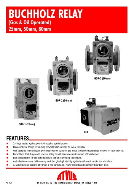
BBAABRELAY TYPEGOR 1RELAY TYPEGOR 2&3RELAY TYPESRIFDFGEHFEHDGEHCCDCRELAY TYPEGOR 1 GOR 2 GOR 3 SRINo. Of Switching SystemsTransformer Rating (MVA)Main Dimensions (mm)Flange Dimensions (mm)Pipe Bore (mm)Surge Test (TRIP) (cm/s)Gas Volume (ALARM) (cc)Velocity Test (cm/s)Element TestHigh Voltage TestInsulation Resistance TestPorosity TestMechanical Strength TestCurrent Rating of SwitchResistance of The SwitchP.C.D.Holes /ThreadFlange Dia.IS 3637, Clause 7.6IS 3637, Clause 7.5IS 3637, Clause 7.8IS 3637, Clause 7.4IS 3637, Clause 7.3IS 3637, Clause 7.3IS 3637, Clause 7.2IS 3637, Clause 7.7IS 3637, Clause 3.3IS 3637, Clause 3.3ABCDEFGH2below 12501282051” Conduit72M1078 square2570 to 13090 to 16570 to 13021to 10250184 or 2152051” Conduit115181505075 to 140175 to 22575 to 14090 to 1602With oil, at 1.4 Kg/cm for 15 minutes2000 Vat 50 Hz for 1minuteGreater than 10 megaohms with 500 Vmeggar2With oil, at 1.5 Kg/cm for 4hours2With oil, at 8Kg/cm for 1minute2Amp at 240 V,50 Hz AC/DCNot to exceed 0.1 ohm across the electrodes of mercury switch2above 102702152201” Conduit145181858090 to 160200 to 3001OLTC1701192003/4” Conduit72M1078 square2545 to 60N.A.45 to 60Due to our policy of continuous product improvement, dimensions and designs are subject to change.INDUSTRIES689, Block ‘O’, New Alipore, Kolkata -700 053, INDIAPhones: (91-33) 24001101, 24009885 Fax: (91-33) 24007443, 24007043 E-mail: atvus@dataone.in