Catalog for size 150mm - Atvus Industries
Catalog for size 150mm - Atvus Industries
Catalog for size 150mm - Atvus Industries

You also want an ePaper? Increase the reach of your titles
YUMPU automatically turns print PDFs into web optimized ePapers that Google loves.
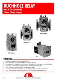
PRESSURE RELIEF VALVE<br />
FOR OIL FILLED TRANSFORMER<br />
Type :T6<br />
FEATURES<br />
• Pressure Die Cast Aluminium flange free of blow holes.<br />
• Stainless Steel deep drawn operating diaphragm, specially coated to prevent sticking with rubber seals.<br />
• Automatic and instantaneous venting and sealing.<br />
• IP 67 protection <strong>for</strong> switch.<br />
• Specially designed reverse wound springs and assembly,provide uni<strong>for</strong>m valve loading and improved relief rates.<br />
• Unique spring retaining system on disc and cover.<br />
• 100% operation test <strong>for</strong> each instrument.<br />
• Springs specially coated to prevent rust.<br />
• Cover electrostatic powder coated <strong>for</strong> protection against corrosion.<br />
• Switch with one NO and one NC contacts.<br />
•<br />
•<br />
Switch with two NO and two NC contacts -optional.<br />
Highly visible flag indicator integrated with the switch.<br />
AT-302 IN SERVICE TO THE TRANSFORMER INDUSTRY SINCE 1971
10<br />
9<br />
7<br />
8<br />
4<br />
5<br />
3<br />
6<br />
1<br />
2<br />
CONSTRUCTION WORKING APPLICATION<br />
The Pressure Relief Valve<br />
consists of a pressure die cast<br />
Aluminium flange (1) with Nitrile<br />
gasket (2) <strong>for</strong> mounting on<br />
trans<strong>for</strong>mer. The Stainless Steel<br />
diaphragm (3) is loaded with two<br />
reverse wound calibrated springs<br />
(4) and seals the 150 mm port<br />
against top and side gasket (5&6).<br />
The deep drawn cover (7) retains<br />
and compresses the spring and is<br />
heldinplacebysixscrews(8).<br />
The cover and the operating disc<br />
have specially designed retainers<br />
to prevent dislocation of springs<br />
duringrepeatedoperations.<br />
The switch assembly (9) <strong>for</strong> alarm<br />
is optional and houses one NO and<br />
one NC contact (four terminals). It<br />
alsohasavisualindicator(10).<br />
When pressure in the tank<br />
rises above the safe limit, the<br />
operating disc moves slightly<br />
upwards from top gasket. This<br />
exposes the trans<strong>for</strong>mer pressure<br />
to agreater area corresponding to<br />
the diameter of side gasket,<br />
resulting in sudden increase of<br />
<strong>for</strong>ce.Thediskliftsinstantaneously<br />
and vents gases, vapour and liquid<br />
till the pressure falls to allowable<br />
values.<br />
These Pressure Relief Valves are<br />
recommendedtobeusedonpower<br />
trans<strong>for</strong>mers.<br />
They are much more effective,<br />
durable and suitable <strong>for</strong> repeated<br />
operations than the conventionally<br />
usedexplosionvent.<br />
NUMBER PER<br />
INSTALLATION<br />
No precise <strong>for</strong>mula is available to<br />
determine the number of pressure<br />
relief valves to be used. However,it<br />
is recommended to use one device<br />
<strong>for</strong> each 35000 litres of cooling<br />
liquidcapacity.
MOUNTING<br />
The Pressure Relief Valve should be preferably mounted in<br />
the horizontal position, top side up. However, it can be<br />
mountedonitsside,inverticalplanealso.<br />
Any pressure head due to side mounting or conservator<br />
tanks, should be taken into consideration (approximately 0.5<br />
psi/foot)whendeterminingoperatingpressure.<br />
INSTALLATION<br />
Clean surface of mounting pad on tank and place the flange<br />
with gasket. Use M12 x30 bolts with acombination of plain<br />
thick washer and spring washer <strong>for</strong> tightening. Ensure that<br />
thegasketisplacedinthegrooveprovidedintheflange.<br />
Check the operation of switch by manually lifting the<br />
operatingrod. After checking, theswitch shouldbe manually<br />
reset by placing the roller type knob back to its original<br />
position.<br />
MAINTENANCE<br />
The Pressure Relief Valve has a rugged construction and<br />
does not require any maintenance. Theoperating pressure is<br />
factory preset and cannot be changed at site. It is strongly<br />
recommended that the compression screws on the cover<br />
shouldneverberemovedwithoutuseofextremecaution.The<br />
operation of switch may be periodically tested by manually<br />
liftingtheoperatingrodandshouldberesetbe<strong>for</strong>eputtingthe<br />
instrumentinservice.<br />
VALVE SPECIFICATIONS<br />
1. Liquid in tank : Trans<strong>for</strong>mer oil<br />
2<br />
2. Operating Pressure : 0.42 Kg/cm (6 PSI)<br />
2<br />
0.56 Kg/cm (8 PSI)<br />
2<br />
3. Operating tolerance : + 0.07 Kg/cm (1.0 PSI)<br />
4. Operating time : Instantaneous<br />
O<br />
5. Operating temperature : 0to 100 C(of trans<strong>for</strong>mer oil)<br />
6. Portopening : 150 mm Dia<br />
7. Valve resetting : Automatic<br />
8. Switch : Limit Switch D.P.D.T.<br />
9. Switch resetting : Manual<br />
2<br />
0.49 Kg/cm (7 PSI)<br />
2<br />
0.70 Kg/cm (10 PSI)<br />
10. Environment : Indoor &Outdoor<br />
DETAILS OF MOUNTING PAD<br />
APPLICATION<br />
TOP VIEW<br />
HORIZONTAL<br />
VERTICAL<br />
SWITCH SPECIFICATIONS<br />
1. Number of switch : 1Limit switch<br />
2. Operation : Automatic<br />
3. Contact rating : AC :240V 10 Amps<br />
5. Weather protection : IP 67<br />
6. Cable entry : 1” Conduit<br />
DC :250V 0.4 Amps<br />
4. Number of contacts : 1NO +1NC<br />
260<br />
155<br />
SECTIONALFRONTVIEW<br />
6NOS. M12 TAPPED HOLE<br />
ON 235P.C.D.<br />
ALL DIMENSIONS ARE IN mm.<br />
DETAILOFMOUNTINGPLATE<br />
(NOT SUPPLIED BYUS)<br />
HORIZONTAL &VERTICAL MOUNTING<br />
2NO +2NC (optional)
262<br />
SWITCH OPERATION<br />
BEFORE VALVE OPERATION<br />
1 2 3<br />
4<br />
TERMINAL NOS.<br />
AFTER VALVE OPERATION<br />
1 2<br />
3 4<br />
WIRING DIAGRAM<br />
ALARM<br />
1<br />
2<br />
SUPPLY<br />
ALARM<br />
3<br />
4<br />
SUPPLY<br />
ToOrder,Or For Quotation, Specify :<br />
1. Model Number<br />
-T6 -With Switch (1 NO +1NC)<br />
-T6-2 -With Switch (2 NO +2NC)<br />
-T6W -Without Switch<br />
2. Operating Pressure<br />
a) 0.42 Kg/cm2 (6 PSI)<br />
b) 0.49 Kg/cm2 (7 PSI)<br />
c) 0.56 Kg/cm2 (8 PSI)<br />
d) 0.70 Kg/cm2 (10 PSI)<br />
e) Other than above<br />
Due to our policy of continuous product improvement, dimensions and designs are subject to change.<br />
INDUSTRIES<br />
689, Block ‘O’, New Alipore, Kolkata -700 053, INDIA<br />
Phones: (91-33) 24001101, 24009885 Fax: (91-33) 24007443, 24007043 E-mail: atvus@dataone.in