NEMA Standards Publication 243-2004 Digital Addressable Lighting ...
NEMA Standards Publication 243-2004 Digital Addressable Lighting ...
NEMA Standards Publication 243-2004 Digital Addressable Lighting ...

You also want an ePaper? Increase the reach of your titles
YUMPU automatically turns print PDFs into web optimized ePapers that Google loves.
NS <strong>243</strong>-<strong>2004</strong>, Part 2-<strong>2004</strong><br />
Page 3<br />
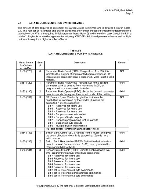
2.5 DATA REQUIREMENTS FOR SWITCH DEVICES<br />
The amount of data required to implement an Switch Device is minimal, and is detailed below in Table<br />
2.1. The number of Parameter and Switch Banks that the vendor chooses to implement determines the<br />
total table size. With the required initial parameter bank (Bank 0) and one switch bank (switch bank 0) a<br />
total of 15 bytes is required (single functionality e.g. ON/OFF). Additional parameter banks and multiple<br />
button units require a higher number of bytes.<br />
Table 2-1<br />
DATA REQUIREMENTS FOR SWITCH DEVICE<br />
Read Byte #<br />
0xXX=Hex<br />
(xxx)=Dec<br />
Byte<br />
#<br />
Description<br />
0x80 (128) 0 Parameter Bank Count (PBC): Ranges from 1 to 255, this<br />
indicates the number of implemented parameter banks. If 1,<br />
then a single parameter bank is supported. Zero is not a valid<br />
number.<br />
0x81 (129) 1 Parameter Bank Read/Write (PBRW): Set to the desired<br />
parameter bank to be read from (command 0x00), or<br />
programmed (commands 0x81 to 0x8e).<br />
0x82 (130) 2 Parameter Bank Operate (PBO): Set to the desired parameter<br />
bank to operate from given the current mode of the building<br />
0x83 (131) 3 FB (Feature Byte): Read only byte that indicates the<br />
capabilities implemented by the vendor (0 means not<br />
supported, 1 means supported)<br />
Bit 7 – Reserved for future use<br />
Bit 6 – Reserved for future use<br />
Bit 5 – Reserved for future use<br />
Bit 4 – Supports status information<br />
Bit 3 – Supports 3-byte outputs<br />
Bit 2 – Supports programming feature outputs<br />
Bit 1 – Supports 2-byte outputs<br />
Bit 0 – Multiple switch implemented<br />
PB The actual Parameter Bank (bytes 1 to 3)<br />
0x84 (132) 1 Switch Bank Count (SBC): Ranges from 1 to 255, this gives<br />
the count of buttons the units is supporting. Zero is not a<br />
valid number.<br />
0x85 (133) 2 Switch Bank Read/Write (SBRW): Set to the desired switch<br />
bank to be read from (command 0x80), or programmed to<br />
(commands 0x81 to 0x93).<br />
0x86 (134) 3 Sensor Output Enable (SOE): Used to enable/disable two<br />
byte, programming and/or three byte commands:<br />
Bit 7 Reserved for future use<br />
Bit 6 Reserved for future use<br />
Bit 5 Reserved for future use<br />
Bit 4 Reserved for future use<br />
Bit 3 Reserved for future use<br />
Bit 2 set to 1 to enable 3-byte commands<br />
Bit 1 set to 1 to enable programming commands<br />
Bit 0 set to 1 to enable 2-byte commands<br />
Default<br />
N/A<br />
0x01<br />
0x01<br />
N/A<br />
0x01<br />
0x01<br />
0x01<br />
© Copyright 2002 by the National Electrical Manufacturers Association.