Air-Driven Liquid Pumps - Hydraulics International, Inc. PUMP ...
Air-Driven Liquid Pumps - Hydraulics International, Inc. PUMP ...
Air-Driven Liquid Pumps - Hydraulics International, Inc. PUMP ...

You also want an ePaper? Increase the reach of your titles
YUMPU automatically turns print PDFs into web optimized ePapers that Google loves.
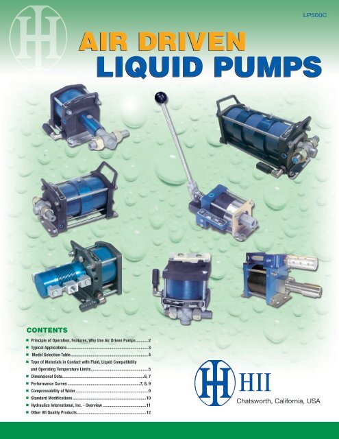
LP500C<br />
<strong>Air</strong> driven<br />
liquid <strong>Pumps</strong><br />
contents<br />
■ Principle of Operation, Features, Why Use <strong>Air</strong> <strong>Driven</strong> <strong>Pumps</strong>............2<br />
■ Typical Applications.............................................................................3<br />
■ Model Selection Table.........................................................................4<br />
■ Type of Materials in Contact with Fluid, <strong>Liquid</strong> Compatibility<br />
and Operating Temperature Limits......................................................5<br />
■ Dimensional Data.............................................................................6, 7<br />
■ Performance Curves.....................................................................7, 8, 9<br />
■ Compressability of Water.....................................................................9<br />
■ Standard Modifications......................................................................10<br />
■ <strong>Hydraulics</strong> <strong>International</strong>, <strong>Inc</strong>. - Overview..........................................11<br />
■ Other HII Quality Products .................................................................12<br />
Chatsworth, California, USA
PRINCIPLE OF OPERATION<br />
<strong>Hydraulics</strong> <strong>International</strong> air driven liquid pumps operate on the<br />
principle of differential working areas. An air piston drives a<br />
smaller diameter plunger or piston to provide a pressure ratio.<br />
The pressure ratio is the method of determining maximum outlet<br />
pressure available. <strong>Hydraulics</strong> <strong>International</strong> model numbers<br />
reflect the nominal pressure ratio of the pumps.<br />
<strong>Hydraulics</strong> <strong>International</strong> liquid pumps will cycle automatically<br />
when compressed air is first applied to the drive. It will start<br />
cycling at its maximum speed thus producing maximum fluid<br />
flow. At this stage, the pump is acting as a transfer pump, filling<br />
the pressure system with fluid. As resistance increases in the<br />
system (creating backpressure to the pump), the pump will<br />
decrease its reciprocating action. Backpressure in the system<br />
finally balances with the incoming air drive pressure times the<br />
ratio. At this point, the pump will stall and maintain pressure<br />
without consuming any energy. If there is further demand on the<br />
system for flow, the pump will automatically start cycling again.<br />
FIGURE 1. CROSS SECTION OF MODEL 5L-SS-RATIO<br />
features<br />
■<br />
■<br />
■<br />
■<br />
<strong>Air</strong> Drive line lubrication not required.<br />
Self-priming for immediate operation.<br />
Compatible with all hydraulic fluids, plain water, distilled &<br />
deionized water, solvents, mild chemicals and most liquefied<br />
aerosol type gases.<br />
Range of models to provide up to 80,000 psi intermittent<br />
output pressure.<br />
■<br />
■<br />
■<br />
Stainless steel hydraulic body, check valves, and trim are<br />
standard, except -4 and -7 models.<br />
Alternative gases that can drive the pump include nitrogen,<br />
vapor from liquefied gas, pipeline natural gas and sour<br />
natural gas with proper modifications.<br />
Offer a wide range of standard modifications.<br />
WHY USE AIR DRIVEN LIQUID <strong>PUMP</strong>S<br />
■<br />
■<br />
■<br />
■<br />
■<br />
Hydraulic pressure is held without energy consumption.<br />
Explosion proof ... requires no electrical power or<br />
connections.<br />
Intrinsically safe.<br />
Compact, lightweight and weatherproof.<br />
Easy to adapt automatic controls.<br />
■<br />
■<br />
■<br />
■<br />
■<br />
Contamination tolerant.<br />
Outlet stall pressure pre-determined by the air drive<br />
regulator.<br />
High pressure capability - up to 80,000 psi.<br />
Ideal for stop-start applications under full load.<br />
Easy to install and operate.<br />
2<br />
(818) 407 - 3400
TYPICAL APPLICATIONS<br />
■<br />
HYDROSTATIC TESTING:<br />
Any component that is made to hold liquid or gas<br />
pressure needs to be carefully tested after manufacture<br />
or repair to verify its integrity, and/or to calibrate it. H.I.I.<br />
air driven pumps can simplify this requirement in a<br />
broad range of industries.<br />
■<br />
CLAMPING-PRESSING-RELEASING:<br />
Hydraulic cylinders or rams that are required to maintain<br />
an output force without movement for long periods need<br />
a hydraulic pump that can maintain output pressure at<br />
zero flow for a long periods with no heat being<br />
generated. H.I.I. air driven pumps will do this over<br />
virtually any pressure range.<br />
■<br />
VALVE ACTUATION:<br />
Pipeline gas is commonly used for bootstrap operation<br />
of pneumatic valve actuators. But where high force<br />
requirements meet low gas pressures, the size of the<br />
pneumatic actuator needed may be impractical. A gas<br />
driven H.I.I. pump with a small hydraulic actuator can<br />
often solve this at less cost.<br />
■<br />
PORTABLE HYDRAULIC TOOLS:<br />
To be easily handled on the job, these tools must be<br />
compact with minimum weight. This means hydraulic<br />
pressures beyond the reach of rotary hydraulic pumps ...<br />
but easily provided by H.I.I. air driven hydraulic pumps.<br />
For portability of the pump-tank package, the oil supply<br />
need be little more than the displacement of the tool it is<br />
teamed with because overheating can not occur.<br />
Compact HII pump & tank unit<br />
with optional hand pump kit if<br />
air or gas not available<br />
QUICK REFERENCE<br />
INTERNATIONAL EQUIVALENTS<br />
PRESSURE: 1 BAR = 14.5 PSI = 100 Kpa = 1.02 Kg/cm 2<br />
VOLUME:<br />
WEIGHT:<br />
LENGTH:<br />
1 Mpa = 10 BAR = 1000 Kpa<br />
1 LITRE = 61 IN 3 = .26 U.S. GALLON<br />
1 NM 3 = 35.3 SCF<br />
1 Kg = 2.2 LBS<br />
1 IN = 25.4 mm<br />
(818) 407 - 3400<br />
3
Model Selection Table<br />
Item<br />
#<br />
Model with<br />
Ratio Dash<br />
Number 1<br />
Maximum<br />
Outlet<br />
Pressure 1 (PSI)<br />
Volume<br />
Displacement<br />
Per Cycle (IN 3 )<br />
3” Single Acting, Single <strong>Air</strong> Drive<br />
5-3/4” Single Acting, Double <strong>Air</strong> Drive<br />
7” Double Acting 4 , Single <strong>Air</strong> Drive<br />
7” Double Acting 4 , Double <strong>Air</strong> Drive<br />
Inlet<br />
<strong>Liquid</strong> Port Detail 3<br />
Outlet<br />
1 3L-SS-8 1,200 0.82 3/4” NPT 1/2” NPT<br />
2 3L-SS-14 1,950 0.46 3/4” NPT 1/2” NPT<br />
3 3L-SS-25 3,750 0.25 3/8” NPT 1/4” NPT<br />
4 3L-SS-41 6,150 0.15 3/8” NPT 1/4” NPT<br />
5 3L-SS-81 12,150 0.08 3/8” NPT 1/4” NPT<br />
6 3L-SS-125 15,000 2 0.05 3/8” NPT 1/4” NPT<br />
7 3L-SS-220 15,000 2 0.03 3/8” NPT 1/4” SP 5, 6<br />
5-3/4” Single Acting, Single <strong>Air</strong> Drive<br />
8 5L-SS-10 1,500 4.42 1” NPT 3/4” NPT<br />
9 5L-SS-15 2,250 3.07 1” NPT 3/4” NPT<br />
10 5L-SS-30 4,500 1.88 1/2” NPT 1/2” NPT<br />
11 5L-SS-45 6,750 1.24 1/2” NPT 1/2” NPT<br />
12 5L-SS-60 9,000 0.89 1/2” NPT 1/2” NPT<br />
13 5L-SS-115 17,250 0.48 1/2” NPT 1/2” NPT<br />
14 5L-SS-150 22,500 0.36 1/2” NPT 1/4” SP 5, 6<br />
15 5L-SS-205 30,750 0.26 1/2” NPT 1/4” SP 5, 6<br />
16 5L-SS-300 45,000 0.18 1/2” NPT 1/4” SP 5, 6<br />
17 5L-SS-450 67,500 0.12 1/2” NPT 1/4” SP 5, 6<br />
18 5L-SD-20 3,000 4.42 1” NPT 3/4” NPT<br />
19 5L-SD-30 4,500 3.07 1” NPT 3/4” NPT<br />
20 5L-SD-60 9,000 1.88 1/2” NPT 1/2” NPT<br />
21 5L-SD-90 13,500 1.24 1/2” NPT 1/2” NPT<br />
22 5L-SD-120 18,000 0.89 1/2” NPT 1/2” NPT<br />
23 5L-SD-230 34,500 0.48 1/2” NPT 1/4” SP 5, 6<br />
24 5L-SD-300 45,000 0.36 1/2” NPT 1/4” SP 5, 6<br />
25 5L-SD-410 61,500 0.26 1/2” NPT 1/4” SP 5, 6<br />
26 5L-SD-600 80,000 0.18 1/2” NPT 1/4” SP 5, 6<br />
5-3/4” Single Acting, Triple <strong>Air</strong> Drive<br />
27 5L-ST-900 80,000 0.18 1/2” NPT 1/4” SP 5, 6<br />
5-3/4” Double Acting, Single <strong>Air</strong> Drive<br />
28 5L-DS-4 1,250 24.1 -10 SAE 6 -10 SAE 6<br />
This model uses inlet pressure to assist the force of the drive. e.g. If inlet pressure is 200psi;<br />
drive pressure 100psi; stall will be approx. 200+400=600psi.<br />
29 7L-DS-7 1,250 41.4 -10 SAE 6 -10 SAE 6<br />
30 7L-DS-35 5,250 7.8 1-1/4” NPT 1/2” NPT<br />
31 7L-DS-60 9,000 4.7 1-1/4” NPT 1/2” NPT<br />
32 7L-DS-100 15,000 2.8 1-1/4” NPT 1/2” NPT<br />
33 7L-DD-70 10,500 7.8 1-1/4” NPT 1/2” NPT<br />
34 7L-DD-120 18,000 4.7 1-1/4” NPT 9/16” MP 5, 6<br />
35 7L-DD-200 20,000 2.8 1-1/4” NPT 9/16” MP 5, 6<br />
weight: 7-9 lbs.<br />
weighT: 24-27 lbs.<br />
weight: 29-32 lbs.<br />
weight: 34 lbs.<br />
weight: 30 lbs.<br />
weight: 50-54 lbs.<br />
Notes:<br />
1 Dash no. is approx. area ratio of drive vs. liquid section. Max. drive pressure: 150 PSI.<br />
2 Max. rated outlet pressure for stainless steel configuration<br />
3 <strong>Air</strong> drive ports: Inlet: 3L-series - 1/4” NPT, 5L-series - 8 SAE 6 , 7L-series - 3/4” NPT<br />
Exhaust: 3L-series - 1/4” NPT, 5L-series - 1/2” NPT, 7L-series - 1-1/4” NPT<br />
4 Items 30-35 in the 7L Series take in the full displacement on their suction stroke, while discharging 1/2 that volume.<br />
Then on the opposite stroke, the other 1/2 of the volume is discharged to complete one cycle. Item 29 takes in and<br />
discharges 1/2 of its displacement with either direction of stroke. It also uses inlet pressure to assist the force of the<br />
drive, e.g. If inlet pressure is 200 psi; drive pressure 100 psi; stall will be approx. 200 + 700 = 900 psi.<br />
5 1/4 SP 6 fits super pressure threaded and coned 1/4” OD tube. 9/16 MP 6 fits medium pressure threaded and<br />
coned 9/16 OD tube.<br />
6 Ref. table 1 on page 5 for port details.<br />
weight: 85 lbs.<br />
Model Designation System: 1 - 2 3 - 4 - 5<br />
Example: 5L-SD-300-X<br />
Box 1: Pump Series: 3L, 5L, or 7L.<br />
Box 2: Pump Action: S-Single Acting, D-Double Acting<br />
Box 3: Drive Piston(s): S-Single piston, D-Two Pistons<br />
Box 4: Nominal Area Ratio-Drive vs Pump Section<br />
Box 5: Modification (See Page 10)<br />
4<br />
(818) 407 - 3400
type of materials in contact with fluid<br />
Series<br />
Hydraulic Hydraulic<br />
Check Valves<br />
Static<br />
Plunger<br />
Body<br />
Plunger Inlet Outlet O-Rings<br />
Seal<br />
3L<br />
-8 thru -81 316SS 316 SS 316 SS 316 SS BUNA-N UHMWPE 1<br />
-125 thru -220 15-5 PH 316 SS 316 SS 316 SS BUNA-N UHMWPE<br />
5L<br />
-10 thru -230 15-5 PH 15-5 PH 15-5 PH 15-5 PH BUNA-N UHMWPE<br />
-300 thru -900 15-5 PH STELLITE 15-5 PH 15-5 PH BUNA-N UHMWPE<br />
-4 ALUMINUM<br />
15-5 PH<br />
Compounded PTFE<br />
316 SS 316 SS BUNA-N<br />
(Rod & Piston)<br />
(Rod & Piston)<br />
7L<br />
-7<br />
ALUMINUM 316 SS Compounded PTFE<br />
15-5 PH<br />
316 SS BUNA-N<br />
-35 thru -200 15-5 PH (Rod & Piston) 15-5 PH<br />
UHMWPE (Rod & Piston)<br />
Series<br />
<strong>Liquid</strong> compatibility: 3L 5L 7L<br />
Hydraulic Fluid - Petroleum, Water, or Veg. Oil Based Yes Yes Yes<br />
Hydraulic Fluid - Skydrol or Brake Fluids Yes 2 Yes 2 Yes 2<br />
Water - Plain, Distilled, Deionized Yes Yes Yes<br />
Solvents Compatible with BUNA-N Yes Yes Yes<br />
Liquified Gases 3 Yes Yes No 3<br />
Suction Pressures 5<br />
Up to maximum outlet pressure<br />
Limit to approx. 30 PSI.<br />
Except 7L-DS-7:<br />
Approx 500 PSI.<br />
Temperature Limitations: +10°F to +150°F. “V” Modification (pg. 10)<br />
Drive Sections 4 can increase limit to about 200°F<br />
<strong>Liquid</strong> Sections<br />
+180°F Maximum. If higher, contact factory.<br />
Notes: 1 Ultra-High-Molecular-Weight Polyethylene<br />
2 Requires “D” and “E” modifications (pg 10). Note: For most other industrial phosphate ester fluids if drive receives “V” modification,<br />
“D” and “E” modifications not required.<br />
3 Ref. HII technical bulletin TB101. Model 7L-DS-7 is suitable for liquified gases.<br />
4 Pneumatic motors and drives of all types severely cool their drive air or gas while performing work. Unless the drive air is heated<br />
and the dew point is well below 32° F, there is potential for ice to form in the drive resulting in slow down or stopping. This probably<br />
indicates a common misapplication: running the pump under load for a sustained period. For suggestions on how this can be<br />
avoided, contact factory.<br />
5 Although all models will self-prime when tank-top mounted with most fluids, a flooded suction is recommended for models -200<br />
thru -900, all series.<br />
For models 5L-SS-450, -SD-600, -ST-900 in heavy duty hydrostatic testing or isostatic press applications, a supercharge pump<br />
such as model 3L-SS-41 is recommended to extend fatigue life. The supercharge pump should also be protected from reverse<br />
leakage with a relief valve set at 10% above its stall pressure.<br />
TABLE 1. Port Details<br />
Port<br />
Thread, <strong>Inc</strong>hes<br />
-4 SAE 7/16-20<br />
-8 SAE 3/4-16<br />
-10 SAE 7/8-14<br />
1/4" SP 9/16-18<br />
9/16" MP 13/16-16<br />
(818) 407 - 3400<br />
5
dimensional data<br />
5L-SD -60 THRU -600 & 5L-ST -900<br />
2<br />
1<br />
1 21.34” 2 18.60”<br />
All other dimensions remain as illustrated.<br />
6<br />
5L -ST -900 ONLY<br />
1 21.34” 2 18.60”<br />
ALL OTHER DIMENSIONS REMAIN AS ILLUSTRATED.<br />
(818) 407 - 3400
dimensional data<br />
1<br />
1<br />
2<br />
PERFORMANCE CURVES<br />
3L-SS-8 2<br />
3L-SS-14<br />
3L-SS-25<br />
4<br />
4375<br />
7000<br />
3<br />
3L-SS-41<br />
OUTLET PRESSURE - PSI<br />
1200<br />
1000<br />
800<br />
600<br />
400<br />
200<br />
0<br />
14000<br />
12000<br />
10000<br />
8000<br />
A B<br />
150 PSI<br />
C<br />
95<br />
75<br />
50<br />
125 250 375 500<br />
5<br />
3L-SS-81<br />
2000<br />
1600<br />
1200<br />
800<br />
400<br />
0<br />
21000<br />
18000<br />
15000<br />
12000<br />
A<br />
6<br />
50<br />
75<br />
B<br />
75<br />
C<br />
150 PSI<br />
95<br />
150 225 300<br />
3L-SS-125<br />
1<br />
3750<br />
3125<br />
2500<br />
1875<br />
1250<br />
625<br />
0<br />
26250<br />
22500<br />
18750<br />
15000<br />
6000<br />
5000<br />
4000<br />
3000<br />
2000<br />
1000<br />
0<br />
32 64 96 128 160 192<br />
20 40 60 80 100 120<br />
7 3L-SS-220 5L-SS-10<br />
1750<br />
1<br />
1500<br />
1250<br />
1000<br />
8<br />
6000<br />
9000<br />
11250<br />
750<br />
4000<br />
6000<br />
7500<br />
500<br />
2000<br />
3000<br />
3750<br />
250<br />
0<br />
10 20 30 40 50 60<br />
0<br />
6 12 18 24 30 40<br />
0<br />
4 8 12 16 20 24<br />
0<br />
240 480 720 960 1200 1440<br />
flow rate - cu in/min<br />
Notes:<br />
1 Shaded area exceeds rated pressure. For intermittent<br />
use in this area, consult factory.<br />
AIR DRIVE FLOW (DOTTED CURVES)<br />
3L-SERIES<br />
5L-SERIES<br />
A B C<br />
6 SCFM 12 SCFM 18 SCFM<br />
A B C D<br />
15 SCFM 30 SCFM 60 SCFM 75 SCFM<br />
These curves predict the performance of<br />
each model using drive pressures shown<br />
(interpolate for other pressures). Maximum<br />
flow points presume 1/4” I.D. drive line<br />
minimum to 3L Series; 1/2” I.D. minimum<br />
to 5L Series; And 3/4” I.D. minimum to 7L<br />
Series. Note: Limited drive flow does not<br />
inhibit maximum outlet pressure capacity.<br />
(818) 407 - 3400<br />
7
2625<br />
PERFORMANCE CURVES<br />
9 10 11<br />
12<br />
5L-SS-15 5L-SS-30 5L-SS-45<br />
5250<br />
7875<br />
10500<br />
5L-SS-60<br />
2250<br />
4500<br />
6750<br />
9000<br />
1875<br />
3750<br />
5625<br />
7500<br />
1500<br />
3000<br />
4500<br />
6000<br />
1125<br />
2250<br />
3375<br />
4500<br />
750<br />
1500<br />
2250<br />
3000<br />
375<br />
750<br />
1125<br />
1500<br />
0<br />
0<br />
0<br />
160 320 480 640 800 960 100 200 300 400 500 600 65 130 195 260 325 390<br />
0<br />
45 90 135 180 225 270<br />
20125<br />
13 5L-SS-115<br />
14 5L-SS-150<br />
15 5L-SS-205<br />
16<br />
26250<br />
35875<br />
52500<br />
5L-SS-300<br />
17250<br />
22500<br />
30750<br />
45000<br />
OUTLET PRESSURE - PSI<br />
14375<br />
11500<br />
8625<br />
5750<br />
2875<br />
0<br />
78750<br />
67500<br />
56250<br />
45000<br />
18750<br />
25625<br />
37500<br />
15000<br />
20500<br />
30000<br />
11250<br />
15375<br />
22500<br />
7500<br />
10250<br />
15000<br />
3750<br />
5125<br />
7500<br />
0<br />
0<br />
0<br />
24 48 72 96 120 144 17 34 51 68 85 102 14 28 42 56 70 84<br />
10 20 30 40 50 60<br />
17<br />
18<br />
5L-SS-450 5L-SD-20 5L-SD-30 5L-SD-60<br />
3500<br />
5250<br />
10500<br />
3000<br />
4500<br />
9000<br />
2500<br />
3750<br />
7500<br />
2000<br />
3000<br />
6000<br />
19<br />
20<br />
33750<br />
1500<br />
2250<br />
4500<br />
22500<br />
1000<br />
1500<br />
3000<br />
11250<br />
500<br />
750<br />
1500<br />
0<br />
6 12 18 24 30 36<br />
0<br />
180 360 540 720 900 1080<br />
0<br />
130 260 390 520 650 780<br />
0<br />
80 160 240 320 400 480<br />
15750<br />
21 5L-SD-90<br />
22 5L-SD-120<br />
23 5L-SD-230<br />
24<br />
21000<br />
38500<br />
52500<br />
5L-SD-300<br />
13500<br />
18000<br />
33000<br />
45000<br />
11250<br />
15000<br />
27500<br />
37500<br />
9000<br />
12000<br />
22000<br />
30000<br />
6750<br />
9000<br />
16500<br />
22500<br />
4500<br />
6000<br />
11000<br />
15000<br />
2250<br />
3000<br />
5500<br />
7500<br />
0<br />
55 110 165 220 275 330<br />
0<br />
40 80 120 160 200 240<br />
0<br />
20 40 60 80 100 120<br />
0<br />
16 32 48 64 80 95<br />
AIR DRIVE FLOW (DOTTED CURVES)<br />
A B C<br />
3L-SERIES<br />
5L-SERIES<br />
6 SCFM 12 SCFM 18 SCFM<br />
A B C D<br />
15 SCFM 30 SCFM 60 SCFM 75 SCFM<br />
flow rate - cu in/min<br />
8<br />
(818) 407 - 3400
PERFORMANCE CURVES (continued)<br />
70000<br />
60000<br />
50000<br />
40000<br />
30000<br />
20000<br />
25 26 27 28<br />
5L-SD-410 5L-SD-600 5L-ST-900<br />
105000<br />
157500<br />
900<br />
5L-DS-4<br />
1 1<br />
90000<br />
135000<br />
80000<br />
750<br />
A B C D<br />
150 PSI<br />
75000<br />
112500<br />
600<br />
60000<br />
90000<br />
80000<br />
45000<br />
450<br />
67500<br />
95<br />
30000<br />
45000<br />
300<br />
75<br />
10000<br />
15000<br />
22500<br />
150<br />
50<br />
OUTLET PRESSURE - PSI<br />
0<br />
0<br />
0<br />
12 24 36 48 60 72<br />
8 16 24 32 40 48<br />
5 10 15 20 25 30<br />
29<br />
30<br />
29 1200<br />
7L-DS-7<br />
7L-DS-35<br />
7L-DS-60<br />
A B C D<br />
A A B B C C D<br />
D<br />
A A B BC C D D A AB B C C D<br />
D<br />
1000<br />
A ABA BC BCDC DD A AB A BC B CCD<br />
DD<br />
150 PSI<br />
4000<br />
100 100 PSI<br />
PSI<br />
6000<br />
100 100 PSI<br />
PSI<br />
100 100 PSI 100 PSI PSI<br />
100 100 PSI<br />
PSI<br />
100 100 PSI 100 PSI PSI<br />
800<br />
40 0 500 1000 1500 2000 0 300 600 900 1200 1500 0 200 400 600 800 1000<br />
3000<br />
600<br />
80<br />
80<br />
95<br />
80 80 80<br />
80<br />
80<br />
4000<br />
75<br />
60<br />
60<br />
2000<br />
60<br />
60<br />
60<br />
60<br />
400<br />
60 60 60<br />
60 60 60<br />
80<br />
80<br />
80 80 80<br />
2000<br />
50<br />
200<br />
1000<br />
33 34 35<br />
7L-DD-70<br />
7L-DD-120<br />
7L-DD-200<br />
14000<br />
A A B BC C D<br />
D<br />
1<br />
A AAB BC BCDC DD<br />
100 100 PSI<br />
PSI<br />
A A B BC C D<br />
D<br />
100 100 PSI 100 PSI PSI<br />
8000<br />
A AAB BC BCC D DD<br />
10500<br />
A AB BC CD<br />
D<br />
20000<br />
100 100 PSI<br />
PSI<br />
100 PSI<br />
100 100 PSI 100 PSI PSI<br />
100 PSI<br />
6000<br />
80<br />
7000<br />
14000<br />
80<br />
80<br />
80<br />
80 80 80<br />
80<br />
80 80<br />
4000<br />
60<br />
60<br />
60<br />
60<br />
60 60 60<br />
60 60 60<br />
3500<br />
7000<br />
60<br />
60<br />
2000<br />
0 200 400 600 800 1000 0 200 400 600 800 0 150 300 450 600<br />
31<br />
0<br />
500 1000 1500<br />
12000 A AAB BC B CD<br />
C DD<br />
8000<br />
32<br />
60 60 60<br />
4000<br />
100 100 PSI 100 PSI PSI<br />
80 80 80<br />
0 200 400 600 800<br />
AIR DRIVE FLOW (DOTTED CURVES)<br />
A B C D<br />
5L-SERIES 15 30 60 75<br />
A ABABC BCD<br />
C DD<br />
SCFM SCFM SCFM SCFM<br />
A<br />
100 100 PSI 100 PSI PSI<br />
B C D<br />
7L-SERIES 45 85 120 165<br />
SCFM SCFM SCFM SCFM<br />
80 80 80<br />
7L-DS-100<br />
Notes:<br />
1 Shaded area exceeds 60 60 60rated pressure.<br />
For intermittent use in this area,<br />
consult factory.<br />
flow rate - cu in/min<br />
PSI X 1000<br />
PSI X 1000<br />
120<br />
110<br />
100<br />
90<br />
80<br />
70<br />
60<br />
50<br />
40<br />
30<br />
20<br />
10<br />
0<br />
A A B B C C D<br />
D<br />
COMPRESSABILITY OF WATER A AAB @ B68° BC CF<br />
C D DD<br />
150 150 PSI<br />
PSI<br />
150 150 PSI 150 PSI PSI<br />
EXTRAPOLATED<br />
95<br />
95<br />
95 95 95<br />
75<br />
75<br />
75 75 75<br />
50<br />
50<br />
50 50 50<br />
SOURCE: MARKS' STANDARD HANDBOOK FOR<br />
MECHANICAL ENGINEERS - 9 TH ED.<br />
1 2 3 4 5 6 7 8 9 10 11 12 13 14 15 16 17 18<br />
PERCENT<br />
PERCENT<br />
(818) 407 - 3400<br />
9
STANDARD MODIFICATIONS<br />
■<br />
“B” Bottom Inlet. See dimensional data pg.6 and selection table pg. 4. This modification applies only to model<br />
item numbers 10 through 17 and 20 through 27. It is not available for item 28 or 29. It is standard on items 1-9, 18,<br />
19, and 30-35 (which are not available with side inlet).<br />
■<br />
■<br />
■<br />
■<br />
■<br />
■<br />
■<br />
■<br />
■<br />
■<br />
■<br />
■<br />
“D” Distance Piece. All series. Provides vented, dual seal protection where leakage or fumes from pumped fluid<br />
could attack the air drive section with only the single seal. Specify by adding -“D” after model number, e.g. Model<br />
5L-SS-30-D. Double distance piece also available to protect air drive from some high or low temperature liquids.<br />
Specify by adding -“DD” after model number (5L Series only).<br />
“E” EPR (Ethylene Propylene) Static Seals in <strong>Liquid</strong> Section Only. All series. Replaces all Buna static seals.<br />
Provides needed chemical resistance if liquid section is used with liquids incompatible with Buna, such as Skydrol.<br />
Standard Ultra High Molecular Weight Polyethylene plunger seal is not changed. It is compatible with Skydrol. Specify<br />
by adding -“E” after model number, e.g. Model 5L-SS-30-E. Note: -“D” Modification also highly recommended to<br />
protect air drive seals.<br />
“H” Hand Pump Attachment. 3L Series only. Permits supplementary operation of the pump by hand. Useful in<br />
precise testing or emergency backup applications requiring a hand pump in addition to a power pump. Specify by<br />
adding “H” after model number, e.g. Model 3L-SS-41-H.<br />
“L” Low <strong>Air</strong> Drive Pressure. 5L Series only. Allows operation of the pump with an air drive pressure regulated as<br />
low as 2-3 psi. Also includes “X” modification. External pilot pressure must be 30 psi or more. Specify by adding -“L”<br />
after model number, e.g. Model 5L-SS-30-L.<br />
“P” Piped Exhaust. All series. Enables complete capture of exhaust air or gas from both the drive and pilot exhaust<br />
ports. Permits submerged operation inside hydraulic tanks, and/or piping exhausting gases out of the area for safety<br />
considerations. Exhaust ports for drive and pilot are 1/4” NPT and 1/8” NPT respectively on the 3L and 1-1/4” & 1/8”<br />
NPT on the 7L Series. On the 5L Series, drive and pilot exhaust are joined at a 1/2” NPT outlet. Specify by adding<br />
-“P” after the model number, e.g. 5L-SS-30-P.<br />
“S” Single Stroke. 5L Series and 3L series except -4. Useful for testing, metering or single stroke intensifier type<br />
hydraulic applications. Pump cycles once when momentary air pulse is applied to 1/8” NPT “S” port. Pump will not<br />
cycle otherwise. Specify by adding “S” after model number, e.g. Model 5L-SS-30-S.<br />
“RC” Retract Command. 5L Series only except -4. Similar to “S”. Momentary air pulse will put pump on retract<br />
stroke; otherwise pump cycles normally. Used for close control of test pressures. Precision air regulator<br />
recommended.<br />
“V” Viton Sealed Drive Section. 3L, 5L and 7L Series. Replaces all Buna static and dynamic seals. Provides<br />
needed chemical resistance if drive air or gas has entrained substances incompatible with Buna, such as hydrogen<br />
sulfide or some synthetic lubricants sometimes found in plant air compressors. Specify by adding -“V” after model<br />
number, e.g. Model 5L-SS-30-V.<br />
“V1” Viton Static Orings in <strong>Liquid</strong> Section. For higher temperatures than advisable for Buna, and for extra<br />
resistance to some chemicals. Specify by adding “V1” after model number.<br />
“X” External Pilot Port on the Drive Section. All series. Enables start-stop control of drive with small shutoff<br />
valve. 3L, 7L Series 1/8” NPT, 5L Series -4 SAE (7/16”-20 threads). Specify by adding -“X” after model number, e.g.<br />
Model 5L-SS-30-X.<br />
“R” Remove Return Spring in Drive Section. 3L Series only. For use with pressurized suction applications such<br />
as liquified gases. Improves filling action in the pump body on the suction stroke. Usually limited to -8 thru -41 ratios.<br />
“T” 3 Way Cycling Spool in Drive. 5L Series only. For use with pressurized suction applications (As described<br />
for “R” Mod above).<br />
10<br />
(818) 407 - 3400
HYDRAULICS INTERNATIONAL, INC. OVERVIEW<br />
Founded in 1976, HII has evolved into a fully integrated manufacturer of hydraulic and pneumatic test equipment. HII<br />
maintains three modern facilities in Chatsworth, California, totaling 690,000 square feet.<br />
Along with air driven liquid pumps, HII offers air driven gas boosters, air pressure amplifiers, flowmeters, sophisticated<br />
custom systems and components. HII products are designed and manufactured in the USA.<br />
Corporate headquarters and<br />
offices, sales, administration,<br />
fabrication and assembly<br />
engineering, assembly<br />
and test facility<br />
machine shop facility<br />
Notes:<br />
(818) 407 - 3400<br />
11
OTHER HII QUALITY PRODUCTS<br />
AIR DRIVEN GAS BOOSTERS<br />
■ <strong>Air</strong>line lubrication not required<br />
■ Boosts pressure from 50 to 25,000 PSI<br />
■ Lightweight, 1-man portable<br />
■ Corrosion resistant including offshore environment<br />
■ Self-cooling using own exhaust air<br />
■ No electrical connections needed<br />
■ Wide range of models in single acting, double acting,<br />
two stage, and double air drive configuration<br />
AIR DRIVEN air<br />
PRESSURE amplifiers<br />
■ Boosting shop air to pneumatic tools, cylinders and devices<br />
■ Boosting shop air to drive high-pressure pneumatic diaphragm transfer<br />
pumps<br />
■ Boosting shop air to start oilfield and marine diesel engines<br />
■ Maximizing efficiency at pneumatic workstations or machinery<br />
■ Tire pressure top off on large mining vehicles<br />
■ Replace bottled nitrogen for gas testing, lab or production, up to 700 psi<br />
COMPONENTS<br />
■ Check valves - up to 20,000 PSI, up to 2”<br />
■ Needle valves - straight or angled to 5,000 PSI<br />
■ Inline filters rated to 5,000 PSI, 3 to 25 micron<br />
■ Double acting hand pumps - to 3,000 PSI<br />
■ Pressure relief valves - to 60,000 PSI<br />
■ <strong>Liquid</strong> Flowmeters - to 15,000 GPM<br />
■ Gas Flowmeters - to 15,000 CFM<br />
CUSTOM SYSTEMS<br />
■ Ground Support Equipment (portable<br />
and stationary)<br />
■ Component Test Equipment<br />
■ Customer Designed Equipment<br />
■ Central Systems<br />
■ Commercial and Military Applications<br />
■ Self Propelled Aerial Lift Truck<br />
Our products are designed, sourced<br />
and manufactured in the U.S.A.<br />
HYDRAULICS INTERNATIONAL, INC.<br />
9201 Independence Avenue, Chatsworth, CA 91311<br />
Tel: (818) 407-3400 • Fax: (818) 407-3428 • Email: sales@hiipumps.com<br />
www.hiipumps.com<br />
© HYDRAULICS INTERNATIONAL, INC. 2008